Creating views
Define views
With ELITECAD, it is possible to generate 2D drawings, views and sections at the push of a button.

Generation of 2D views and plans
Workshop
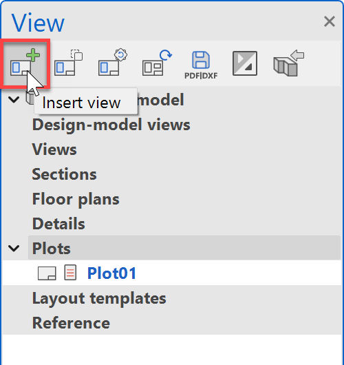
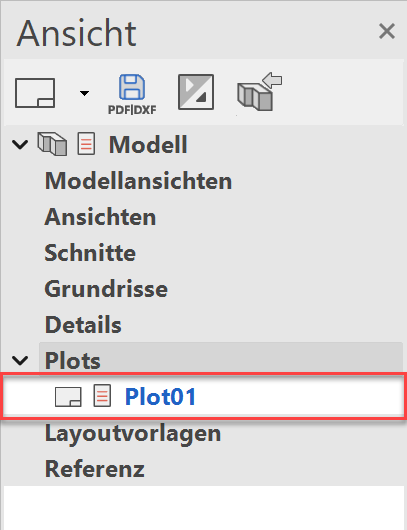
- Open the view manager.
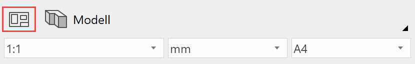
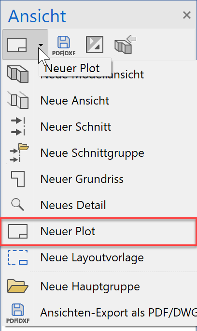
- Create a new plot.
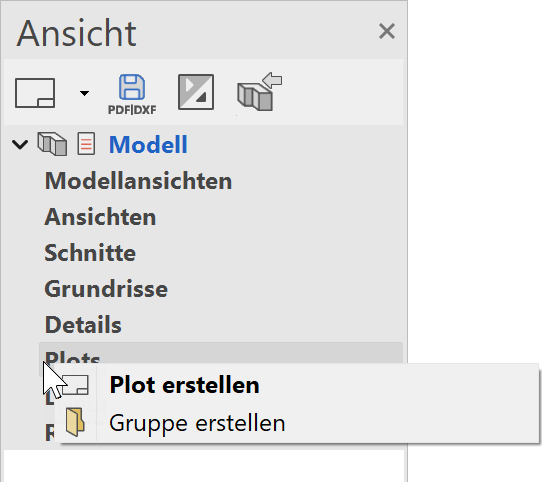
or with the right mouse button:
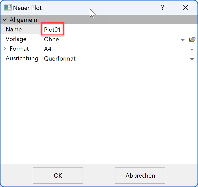
- Make settings and confirm with
 .
.
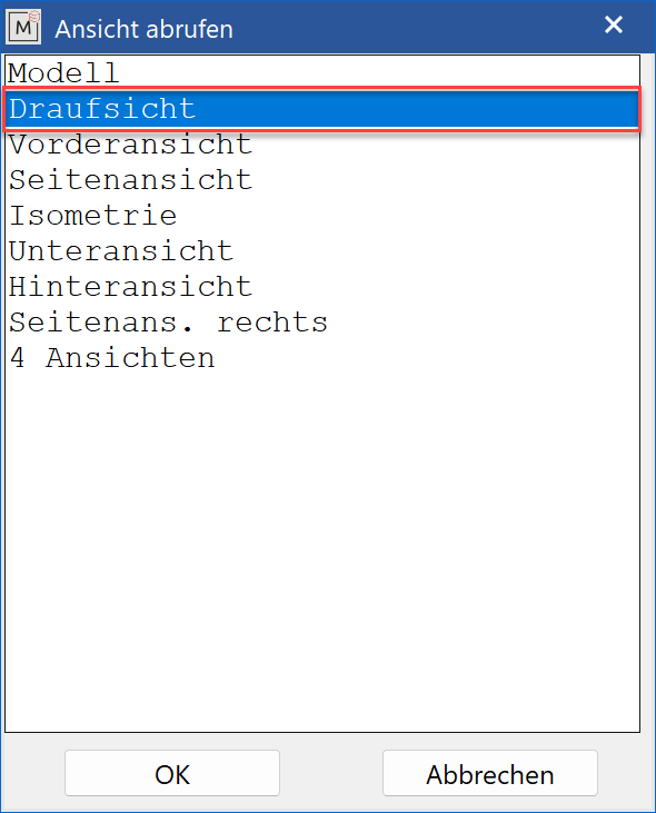
- Now the desired view is selected with "Insert view".
- Select view and confirm with .
- Place the top view on the plot.
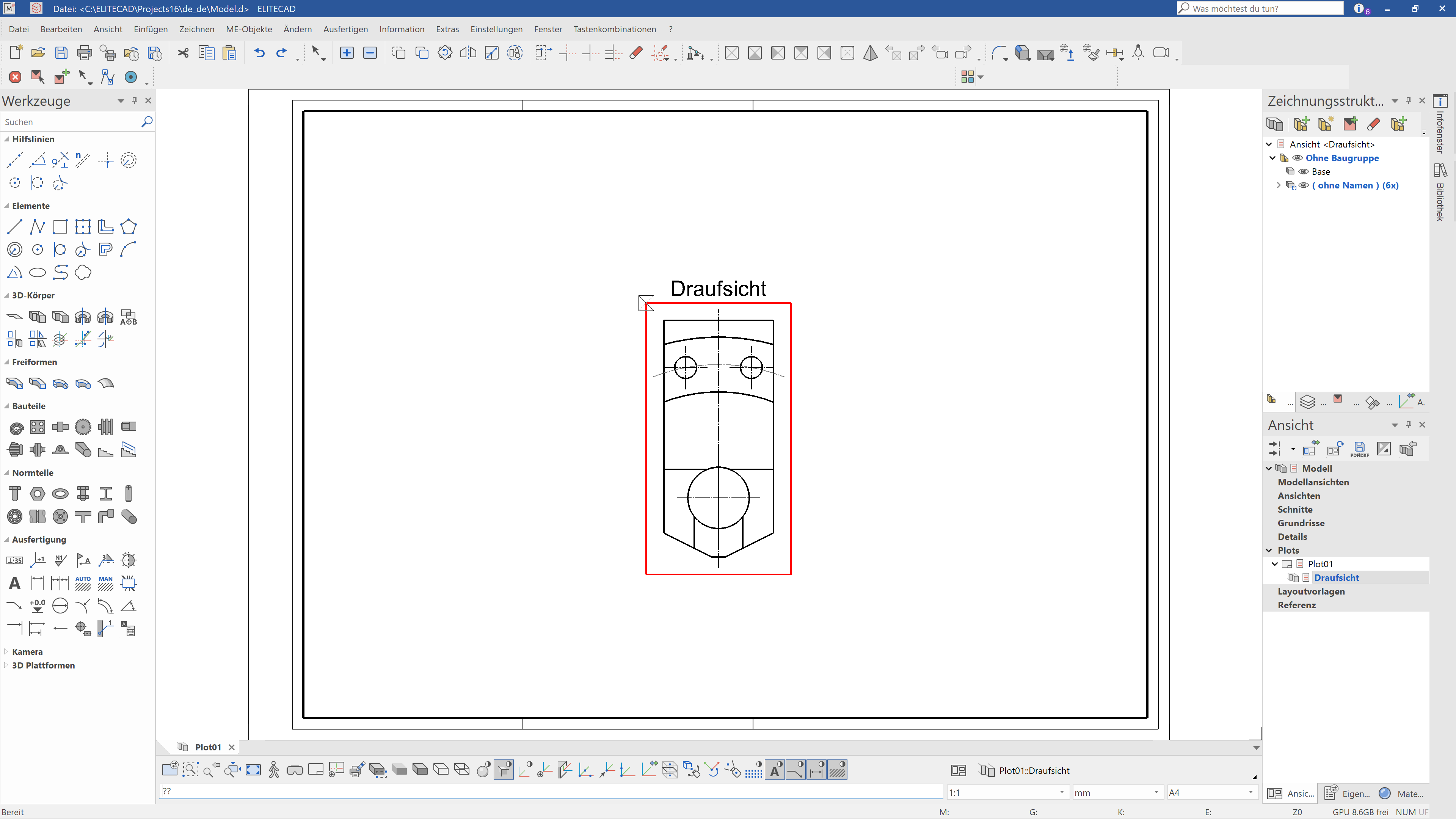
- Insert the top and front view and position them.

Note
With this selection, the filter (group, class, level) is taken into account. If, for example, a group is selected and set up before "SELECT PLOT", only those parts are shown in the plot that have this group name.
Tip
As described in points 4 to 6, all other views could now
can also be inserted into the plot.
Another possibility is shown here:
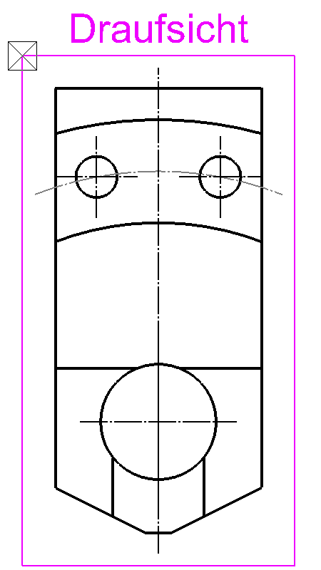
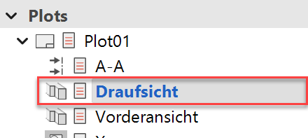
Select (tap once) the top view that has already been inserted. (The frame turns magenta.)
Now click again on "Insert view".
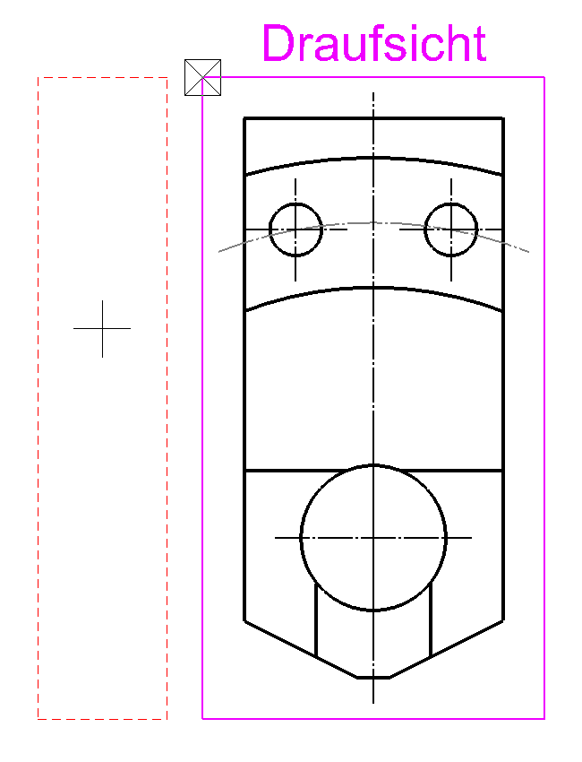
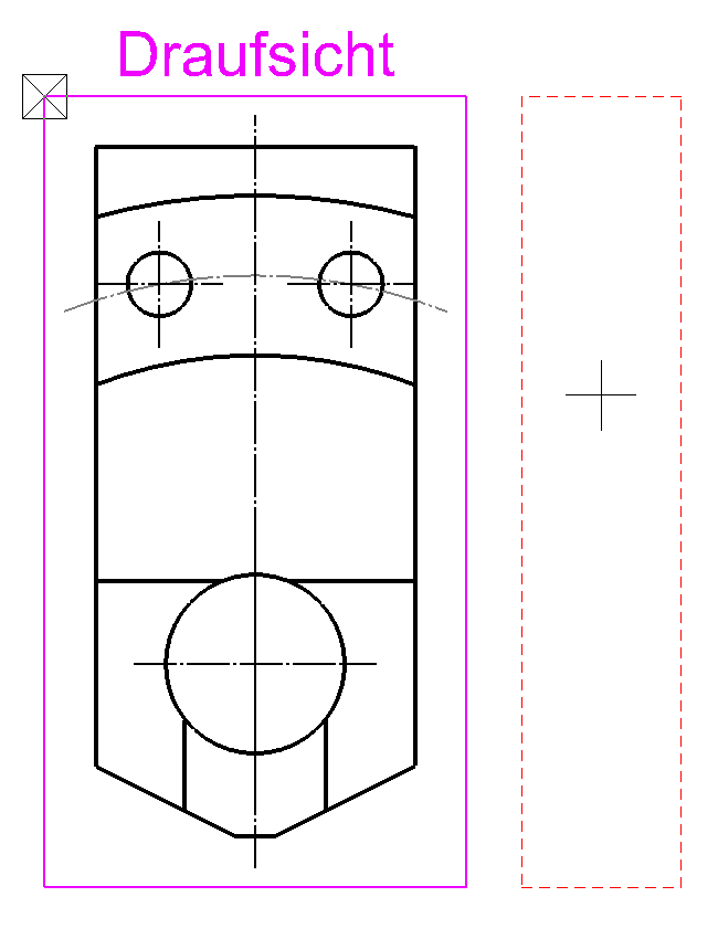
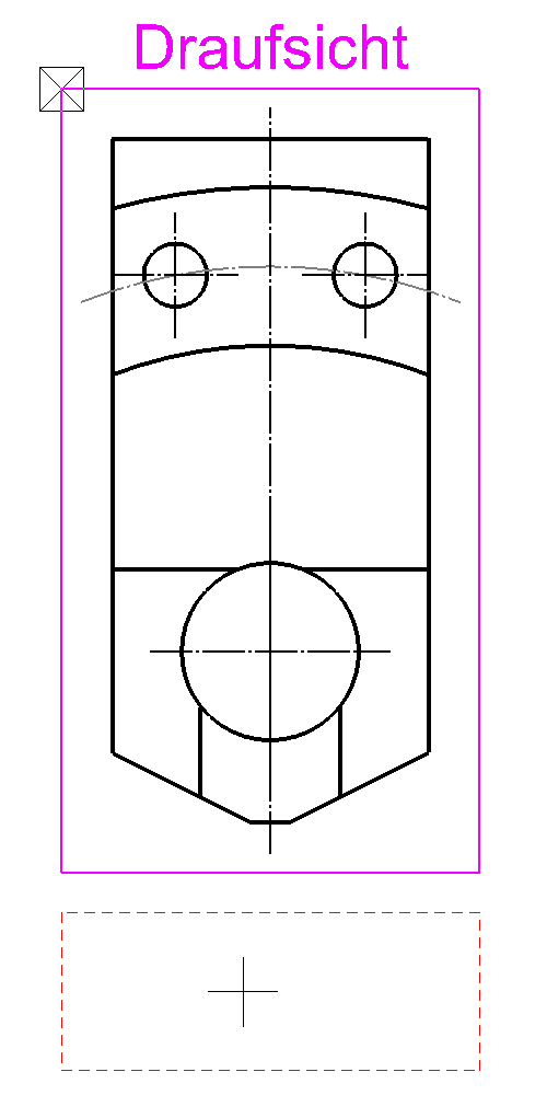
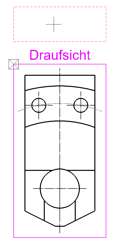
Move the mouse pointer over the "plot" (left, right, up, down). Now all four views can be positioned with a click of the mouse, above the top view, so to speak.
 |
 |
|---|---|
 |
 |
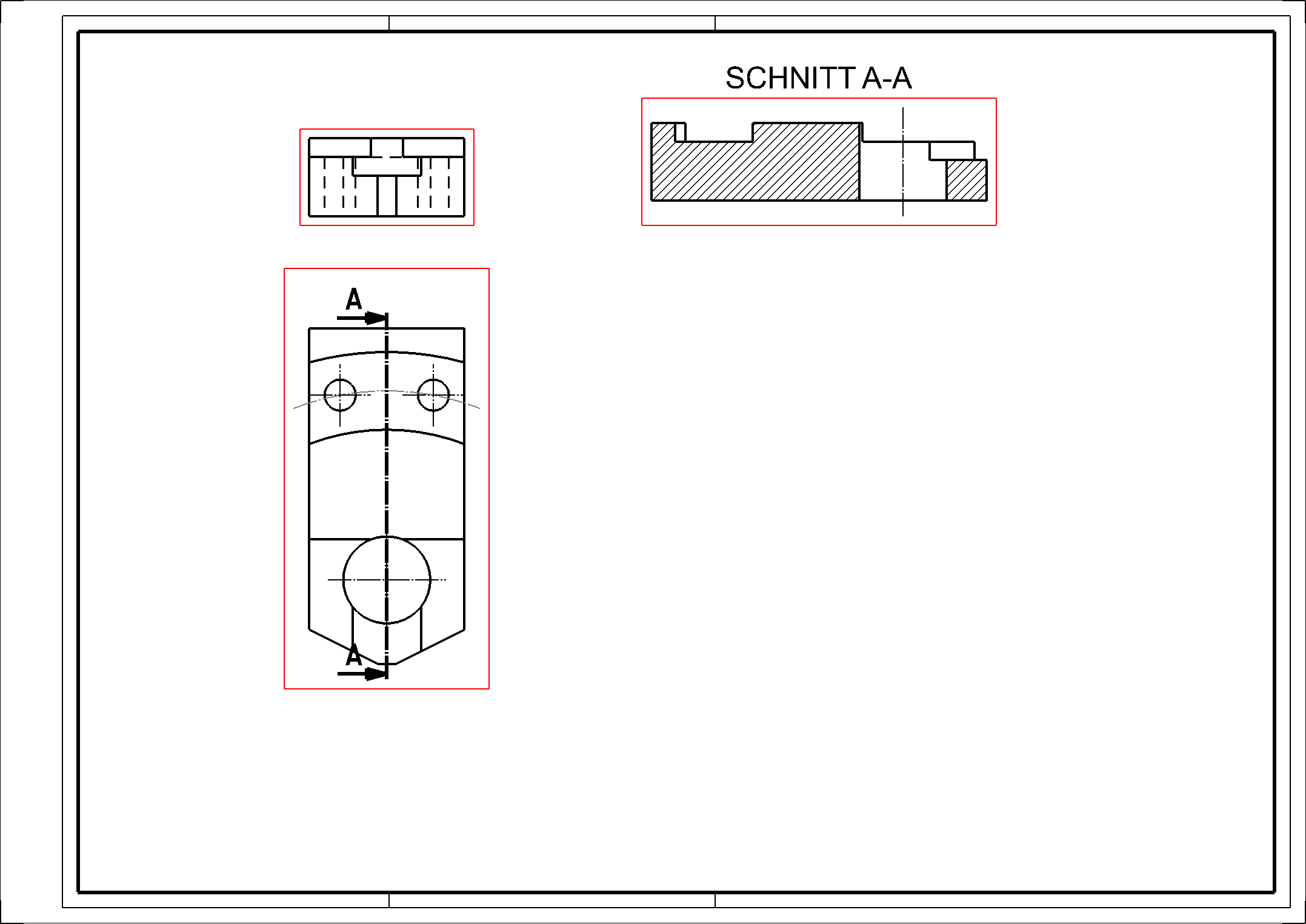
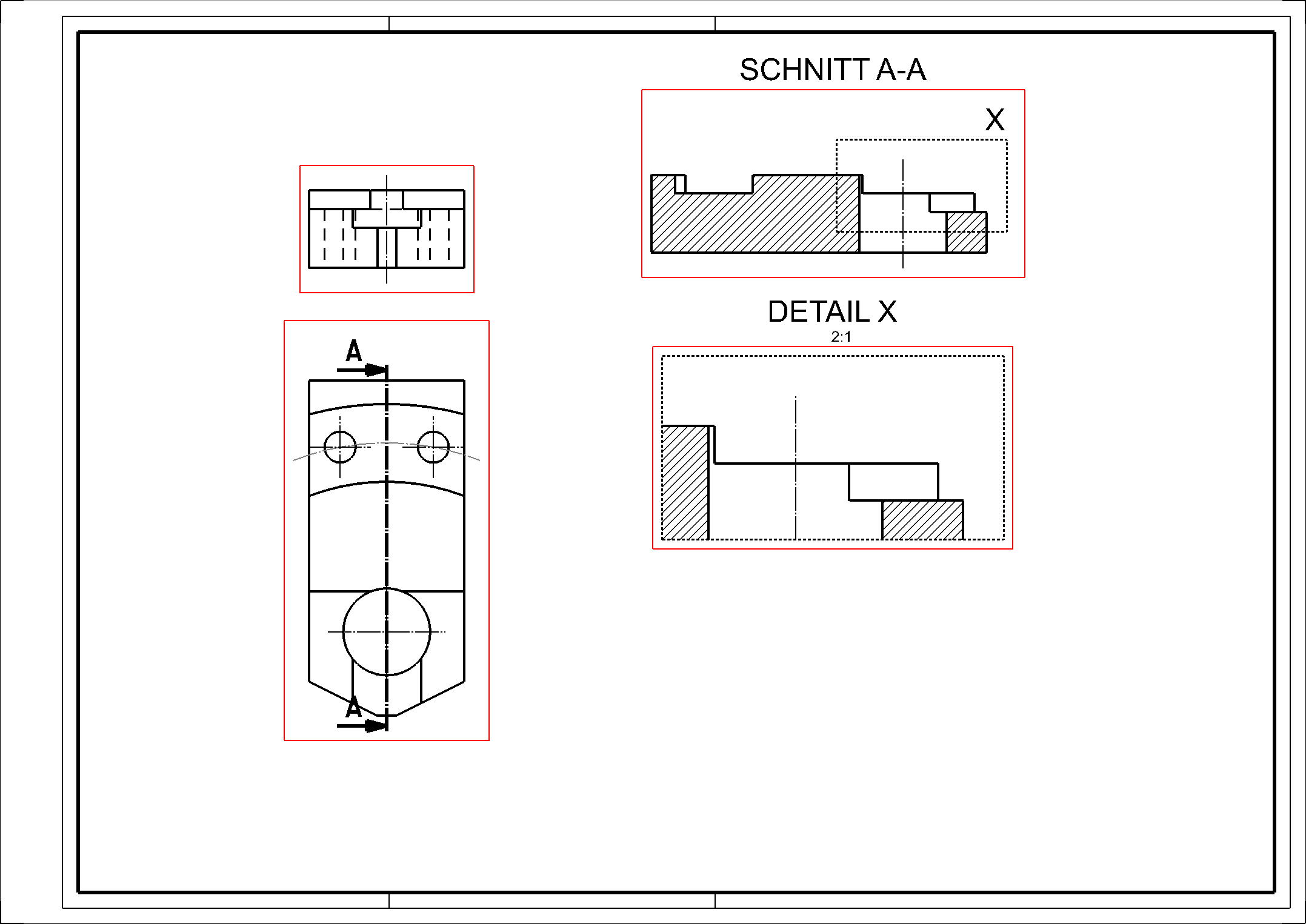
After inserting the views, the result should look like this.

Tip
Individual settings or changes can be made to all views:
- Select the desired view by double-clicking on the red frame. (The frame will be bold.)
- Select "MODIFY VIEW".

- All settings / modifications can be made in the following window.
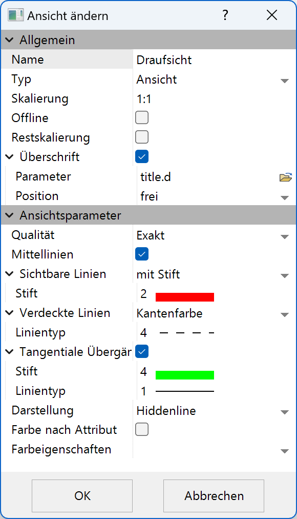
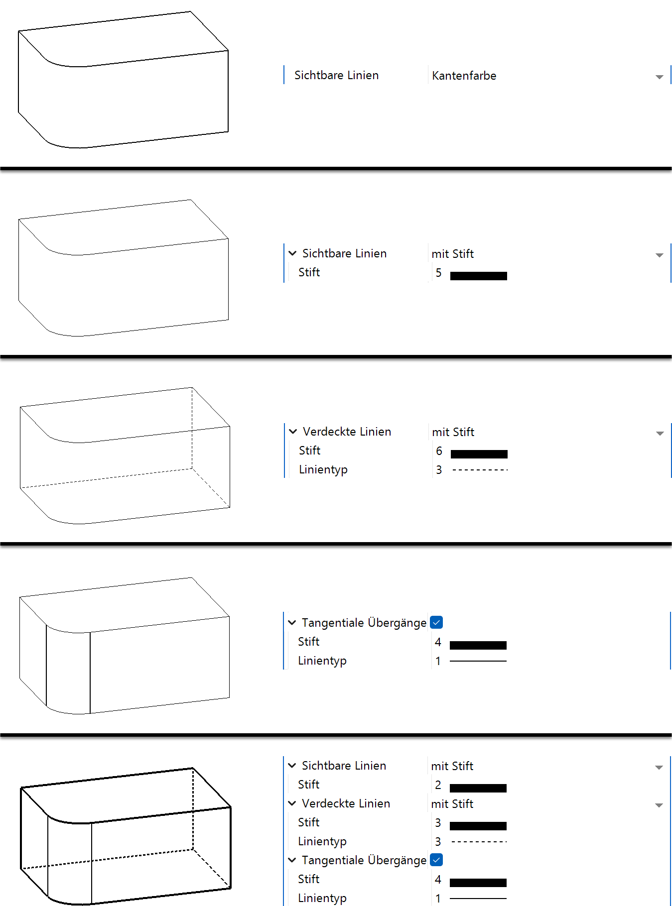
Explanation of the setting options
Define Section
Sections are calculated 2D views. Changes that you make in these sections are not taken into the model. However, changes that you make in the model that would affect the sections can be accepted using the REFRESH VIEW function.
Now you are going to make a section through the model.
Workshop
Create a simple section.
- Switch to the plot.
- Activate the top view. (Double click on its frame.)

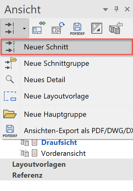
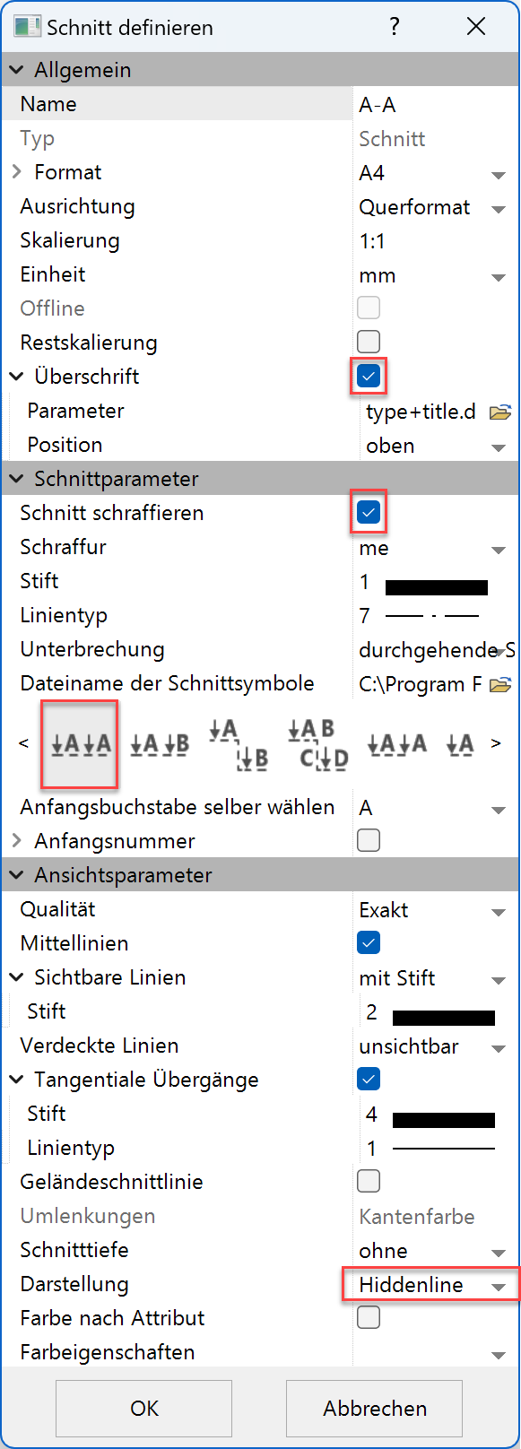
- Define a NEW SECTION.
- Make settings and confirm with .
Enter point1 for cutting course [identical point -> end] - Specify point P1.
Enter point2 for cutting course [identical point -> end] - Specify point P2.
Which direction? - Specify point P3 for the direction.
Position where to? - Draw the section to P4.

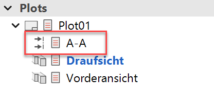
- The section has now been added to the plot.
- Rotate the section 90 degrees and position it.
Define detail
The details are calculated 2D plans. Changes that you make in these details are not taken in the model or in the original plan.
However, changes that you make in the model and affect the details can be accepted using the REFRESH VIEW function.
Workshop
Create a detail of the previously created section A-A.
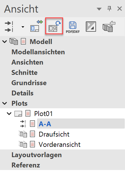
- Switch to section A-A. By clicking in the view manager or double click on the frame of section A-A.
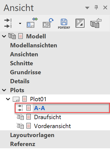
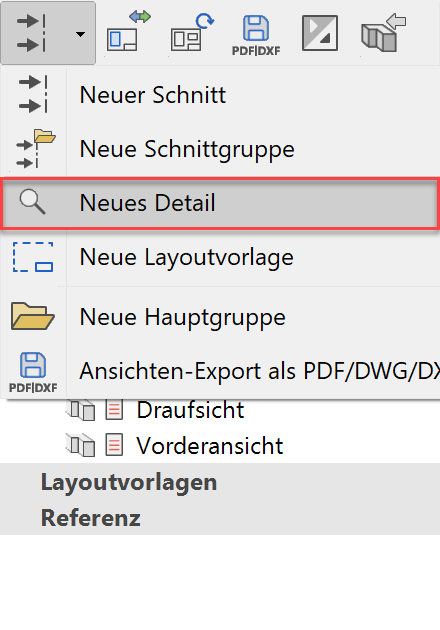
- Define a NEW DETAIL.
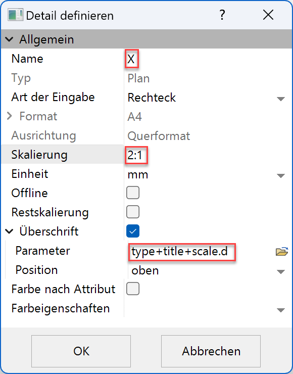
- Make settings and confirm with .
- Enter a corner of the rectangle.
select P1
Diagonal corner of the rectangle?
select P2
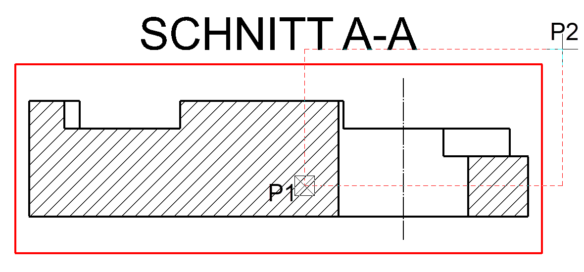
- Place the detail letter X next to the detail outline.
- Then position this detail in the plot.
Dimensions
The dimensions are shown using the top view.
Workshop
- Activate the view in which the measurement should now be carried out. To do this, click on the view in the view management under Plot. The frame of the view now becomes thick and red.
- Select the CHAIN DIMENSION function.
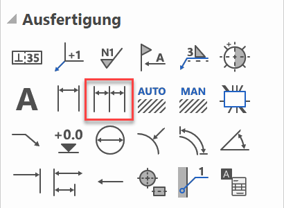
1. Point of dimension? - Select point P1. 2. Point of dimension?
- Select point P2. Position of dimension?
- Select point P3. Since we have selected the CHAIN DIMENSION function, a second measure can now be set immediately. Click on point P4.

- Select the SINGLE DIMENSION function.
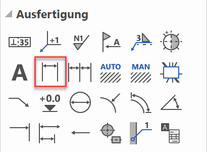
1. Point of dimension? - Select point P1. 2. Point of dimension?
- Select point P2. Position of dimension?
- Select point P3.

- Now set the other dimension lines yourself, as shown in the next figure.

- The diameter symbol "Ø" is required for the next dimension lines. Select SINGLE DIMENSION and activate it.
- Now set the two other dimension lines (diameter) yourself.

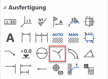
- Now activate the RADIUS DIMENSION function.
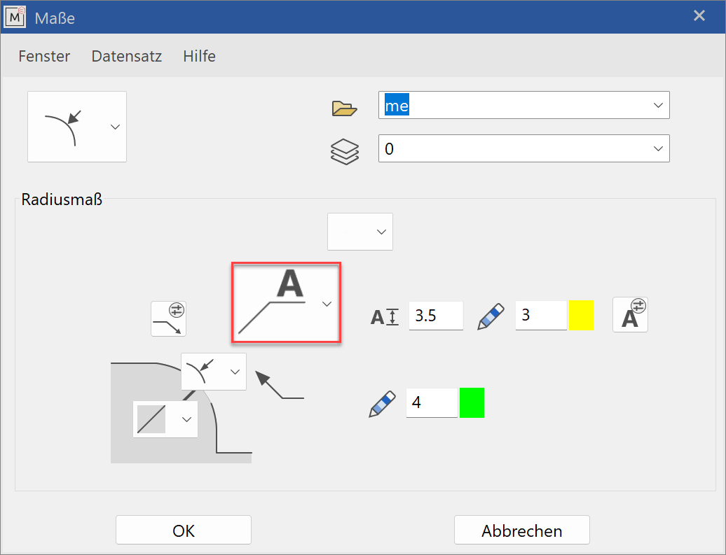
- Open the DIMENSION PARAMETERS.

- Make the following settings and confirm with .
Arc for radius dimensioning? - Select P1.
Text position? - Select P2.

- Now set the other radius dimensions yourself.

Tip
The SINGLE DIMENSION function remains active until you cancel it with Esc.
Save your drawing
Workshop
We are now saving our drawing under a new file name.
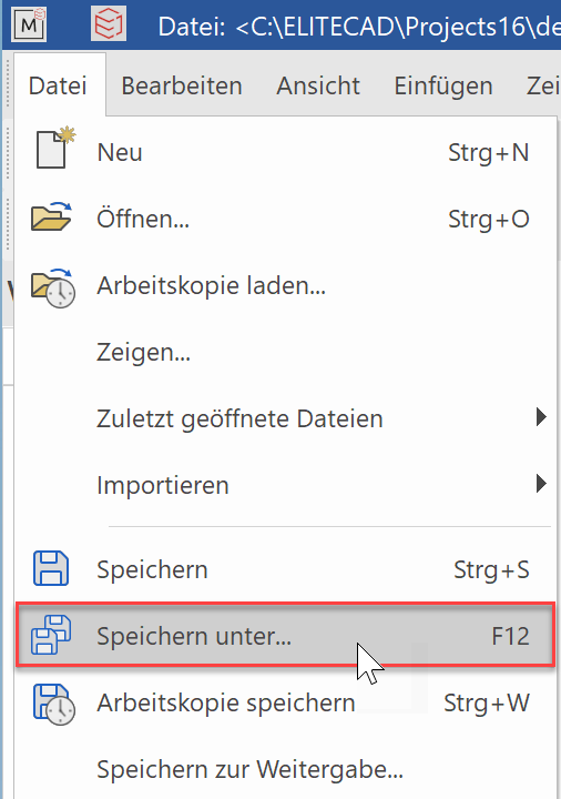 or with the F12 key.
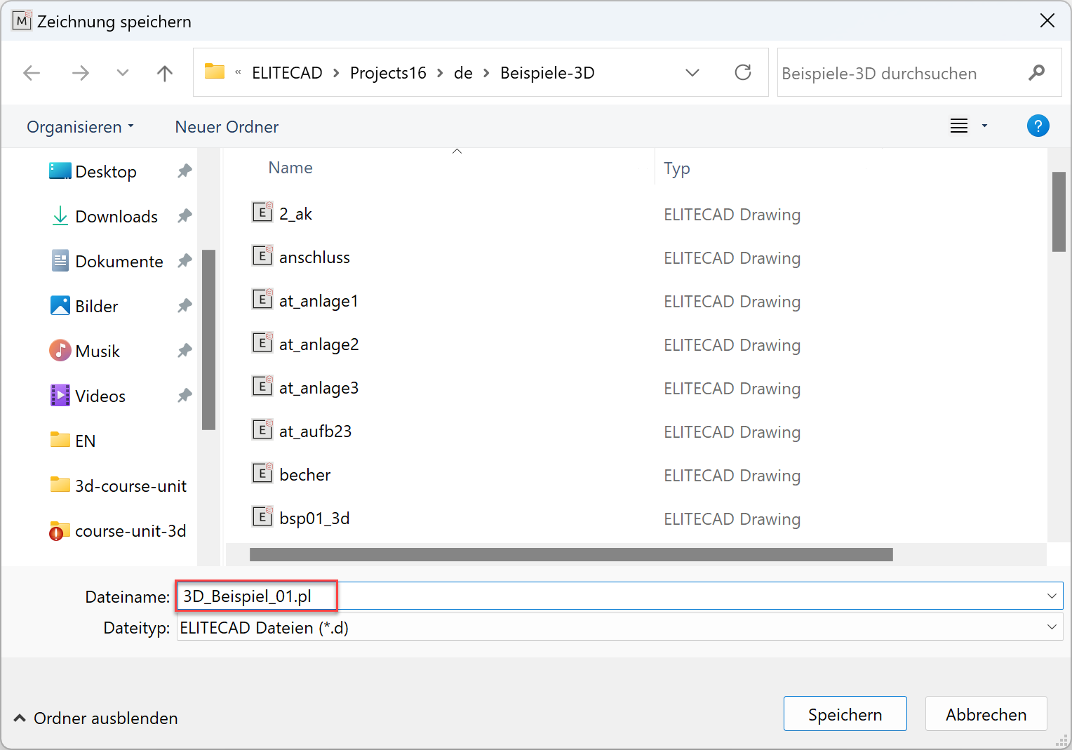
Now enter the desired directory and file name.
Printing
Now all you have to do is get the plan down on paper.
Workshop
- Load the plot "Plot01" onto the screen.
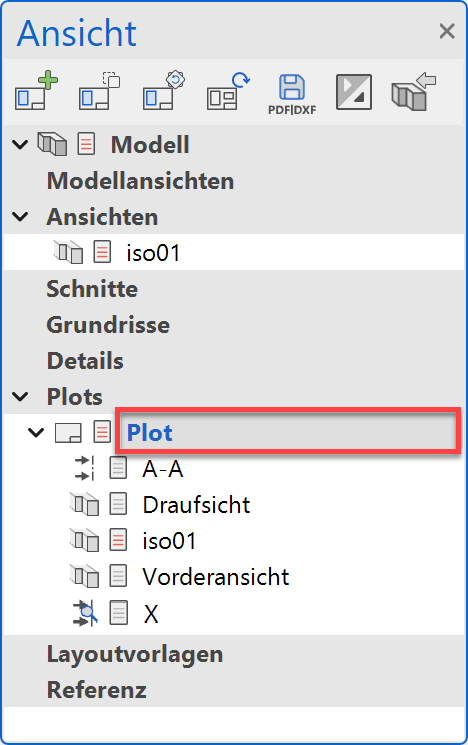
- Click the PRINT icon.

- Select the name of the printer / plotter.
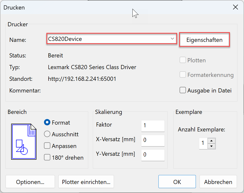
- More settings
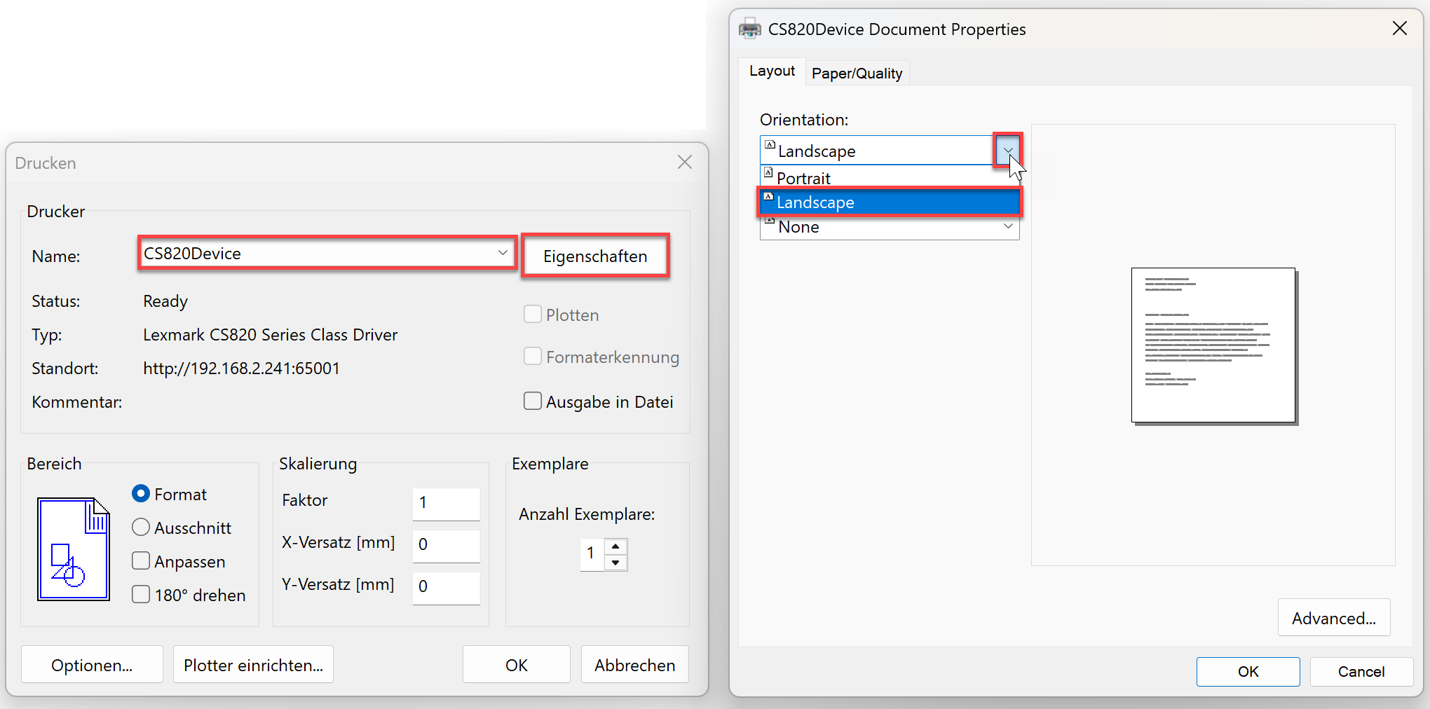
Click on PROPERTIES. The mask looks different depending on the plotter / printer and driver.
If a roll is clamped in the plotter, an oversize must be set for the sheet format. This is the only way to print the edge of the plan.Sample printer: Lexmark CS820
- Confirm both masks with and the plan will be output on the plotter / printer.