Define a surface
As soon as you select the DEFINE SURFACE function, the properties bar appears.
![]()

When defining surfaces, the contour must be closed.
3D-Colour, transparency

The colour and transparency for the 3D display can be selected here.
Visualisation materials
![]()
![]()
With the help of this button it is possible to switch between the colour and visualisation material (VisMat) mode. If you switch to visualisation material mode, a 3D texture can be assigned to the surface.
With the help of the SELECT VISUALISATION MATERIAL button, the selection opens and you can choose between different types of material.
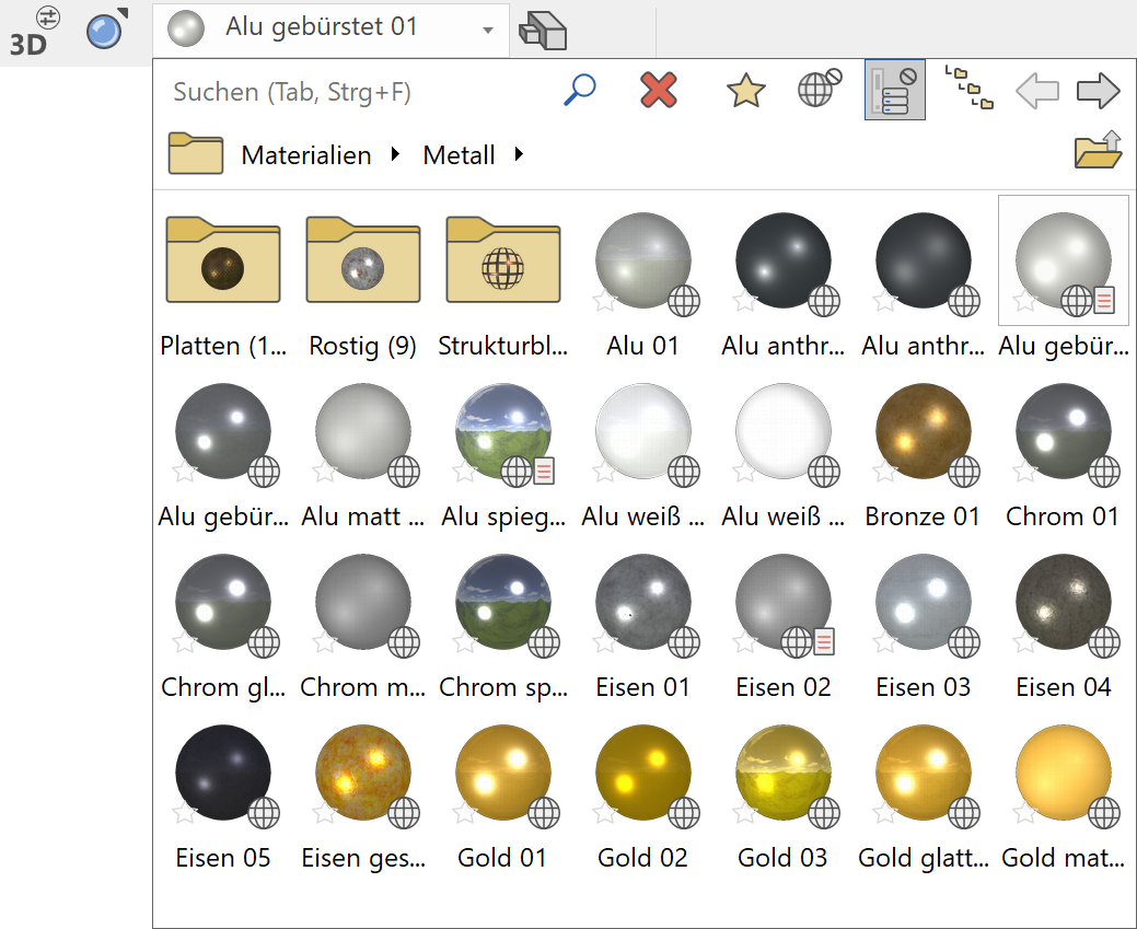
More about using the visualisation material database
Tip
You can also assign a VisMat to the 3D objects using the Visualisation material management. The assignment is made very simply by drag and drop.
Type of 3D definition
There are 3 options for creating a surface:
Either you draw the contour immediately after starting the function or you have already drawn a polygon before calling the function and only "declare" it to be a box or it has already been selected.
The function calls itself again and again in order to be able to draw several surfaces one after the other. When you have finished creating the boxes, you can cancel the function.
Entry over contour
![]()
Entry is done by directly drawing a closed polygon. Once the polygon is completed by a second time clicking on the starting point, a surface will automatically be created and the function ready to start a new polygon should you need to draw multiple surfaces.
Entry over select contour
![]()
If you want to define an existing polygon for the surface, you should make sure that the outline drawn is closed. The surface can be generated by tapping the outline of the polygon.
Entry over selection
If a selection has already been made when the ENTRY OVER SELECT CONTOUR function is selected, a query appears as to whether this selection should be used.
Tip
If polygons are inside one another and they are drawn from the outside inwards, tapped or they are in the selection, recesses result.
Type of input
Limiting surface over height
![]()
The height can be entered as a numerical value (in the currently set unit) in the input line or in the property bar.
Limiting surface by point entry
![]()
With the help of the SNAP FUNCTIONS, the height can be defined directly by selecting a height point in the 3D model.
Limiting surface over 3 points
![]()
The area is defined using 3 points. The height is requested for each point. The definition of the three Z-coordinate points for the inclined surface can be done anywhere on the screen and is not tied to the elements of a model!
Tip
Here, too, it is possible to select points directly in the 3D model. The clicked height is suggested above the input line and can be simply confirmed with Enter.
Limiting surface over surface
![]()
The position is defined by tapping an existing surface.
Change contour
![]()
This can be used to subsequently modify the contour of the surface. After you have clicked on the function, the 2D contour of the surface is automatically displayed. Now change the contour with the normal 2D drawing functions according to your wishes. Make sure that the new contour results in a closed polygon again and terminate the function with the "Contour finished" button, which is visible at the top left.
Tip
If you click on a handle or gripper of the contour after selecting the surface, manipulation functions are also available directly in a toolbar or by pressing Tab on the cursor.
Modify resolution
![]()
This function is used to set the parameters for the 3D resolution. You can switch between a uniform and a curvature-dependent resolution. The analytical data model with nurbs is an exact description of curves and surfaces. For the graphic output, an approximation must be made using facets, which can, however, be as fine as desired. The higher the fineness, the better the graphics, but the longer the computing time.
Define surface 
Workshop
Draw a rectangle, then click on DEFINE SURFACE and set the Entry mode to Select contour. Set the height to 0, the colour to 2 and click on the rectangle.
 |
 |
Several 3D definitions can even be created for the same contour.
Now set the height to 50, the colour to 3 and click on the rectangle again.
 |
Tip
The individual parameters of the surfaces can be modified with the element part selection mode.
To create a slanted surface, set the Entry mode to 3 points. After you have drawn the contour, click on point 1 and enter a height of 0. Then click on points 2 and 3 and enter the heights 100 and 200. This creates a slanted level.
 |
 |