Example object
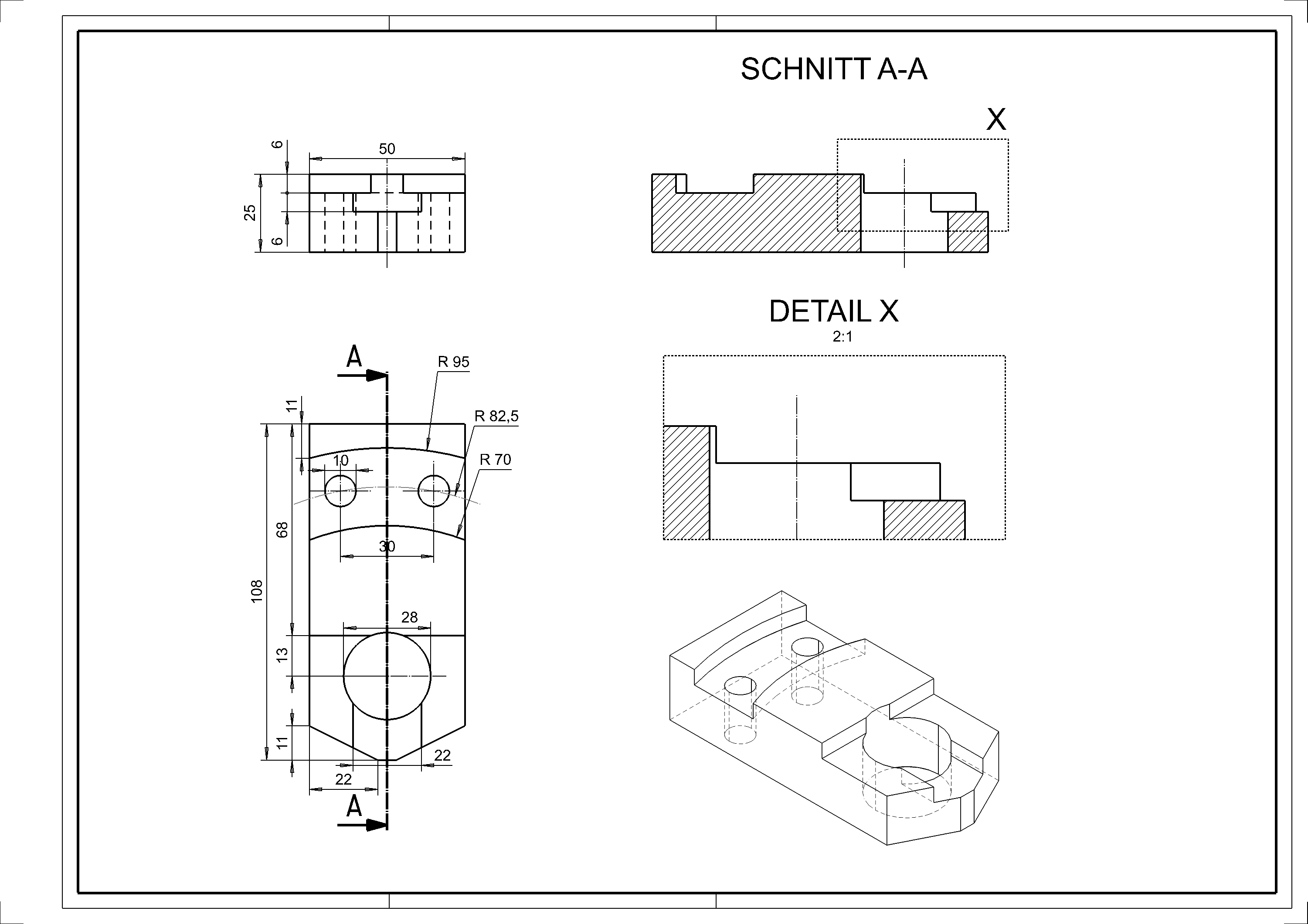
Example dimension sheet BSP01_3D
First, let's look at the desired result.
Box (define base object)
Workshop
- Draw the following contour. Here you can already apply the knowledge from the "COURSE UNIT 2D". (Use the dimensions from the dimension sheet.)

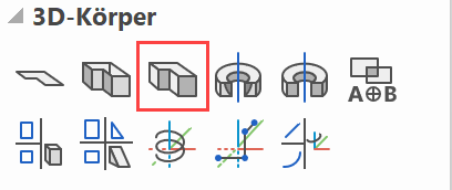
- Select the DEFINE BOX function.
The heights can also be entered in the property bar.
Enter base plane height 0 and top plane height 25

The colour / visualisation material is also specified here. - Now rotate in 3D with the middle mouse button pressed and switch to the solid model (Ctrl+D) and the edges (Ctrl+K).
Work plane on surface
With ELITECAD, work planes can be rotated as required or placed on specific surfaces.
When working in the view, the CLIPPING function is a helpful means of changing the area of visibility.
Workshop
- Place the WORK PLANE ON SURFACE.

Click point P1 on the surface.

- Set the working plane perpendicular and switch to wireframe.
Ctrl+Space, Ctrl+D
- Draw the contours K1 and K2. (Please take the dimensions from the dimension sheet.)

- Select the DEFINE BOX function.
- Enter the following values on the property bar.

- Now turn in 3D with the middle mouse button and switch on the solid model
 and the edges
  .
.

Tip
Switch on the 3D axes so that you have a better overview of the current work plane.


Boolean operation 1
Now you will be remove the two red objects off the main object. This is done with the Boolean operation.
Workshop
- Start with the BOOLEAN OPERATION function.

Now select option A minus B. - Please click definition A (RETURN = end)
Here please select the gray main object (point P1) and then confirm with Enter. (The selected objects are shown in magenta.)

- Please click definition B (RETURN = end)
Here please select the gray main object (point P2 and P3) and then confirm with Enter. (The selected objects are shown in magenta.)


Tip
For the Boolean calculations, the deduction objects should protrude beyond the base contour (object A) if possible.

Save work copy
![]() or with the key combination Ctrl+W.
or with the key combination Ctrl+W.
Boolean operation 2
Workshop
- Draw the following contour. (Please take the dimensions from the dimension sheet.)

- Select the DEFINE BOX function.
- Enter the following values on the property bar.

- Now turn in 3D with the middle mouse button and switch on the solid model and the edges .
- Start with the BOOLEAN OPERATION function.
Now select option A minus B. - Please click definition A (RETURN = end)
Here please select the gray main object (P1) and then confirm with Enter. (The selected objects are shown in magenta.) - Please click definition B (RETURN = end)
Now select the red object (P2) and then confirm with Enter. (The selected objects are shown in magenta.)


