Pedestal
Workshop
- Start a new model
 (e.g.: "bk, plate, pedestal")
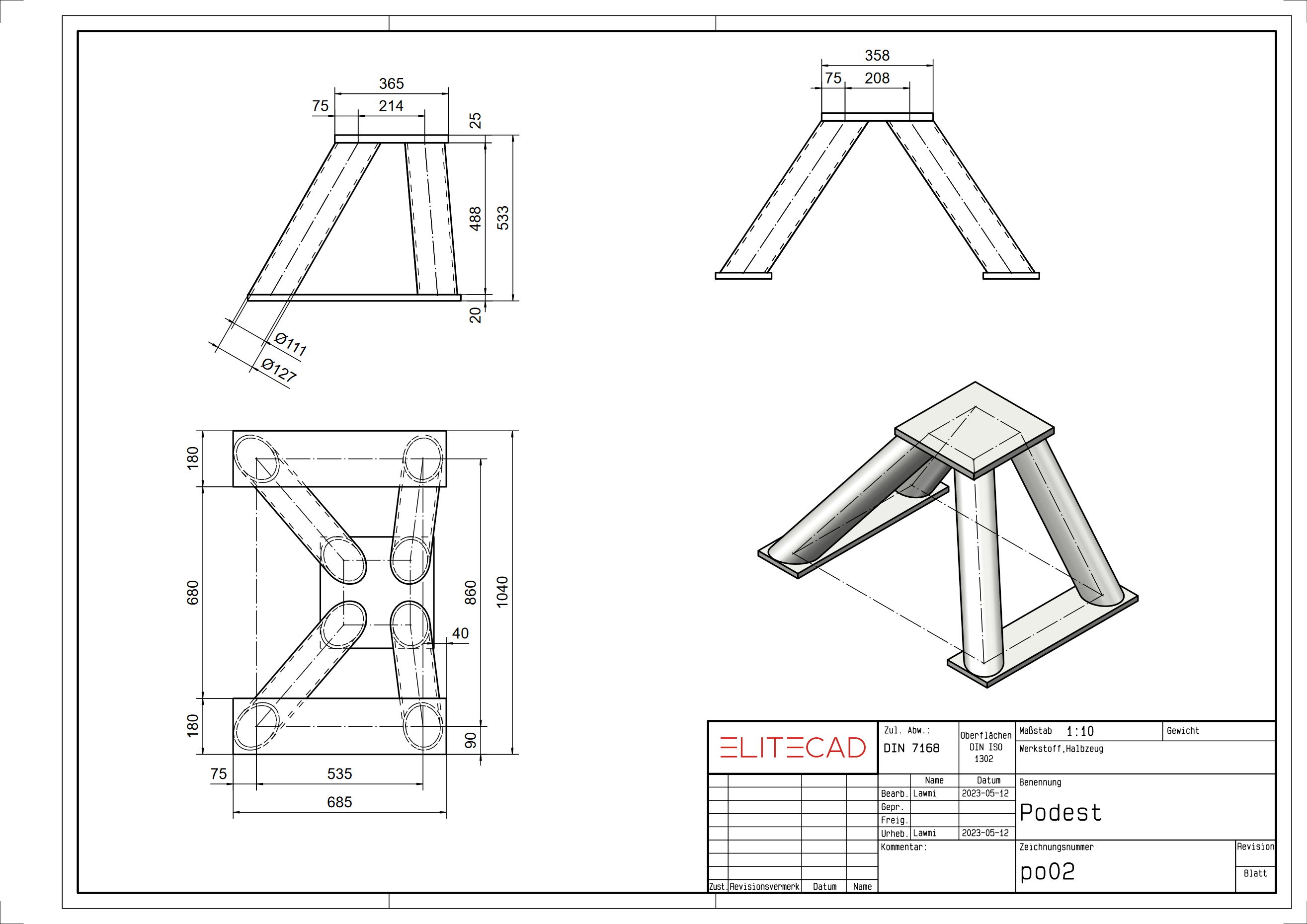
- Draw a rectangle (685 x 180) and put it in the correct position. (R1).
- Define the rectangle as a box with a height of 20.
- Copy the rectangle with COPY SELECTION at position R2.

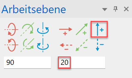
- Move the work plane (WP) upwards by 20 mm.

- Draw the following auxiliary contour, this will be required for the later determination of the WP for the pipes.


- Set the working level up again by 488 mm. Draw the top plate and then define it as a box (height 1 = 0; height 2 = 25).


- Draw the upper auxiliary contour, this will be required for the later determination of the WP for the pipes.


- Select WORK PLANE BY 3 POINTS and use the snap function to catch the following three points.


- Now draw the centre lines for the pipes.

- Switch to WORK PLANE BY NORMAL and set it along the first pipe centre line by clicking on P1 and P2.
Then use the SELECT WORK PLANE ORIGIN and the snap function "Centre of 2 points" to place the origin in the centre of the first centre line. Click again on P1 and P2.

- Now draw the pipe cross-section. Circle 1 with radius 55.5 mm and circle 2 with radius 63.5 mm.

- Define a box.
- Activate the solid model. (Ctrl+D) /

- Change from BASE PLAN DEFINED BY- HEIGHT to BASE PLAN DEFINED BY- SURFACE for the lower plane and click on the upper surface of the lower plate. (P1)
Now change from BASE PLAN DEFINED BY- HEIGHT to BASE PLAN DEFINED BY- SURFACE for the upper plane and click on the lower surface of the upper plate. (P2)


- Now repeat points 11 to 15 again for the second pipe.

- Reset the work plane to the origin.

- Now mirror the two tubes.

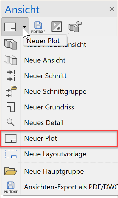
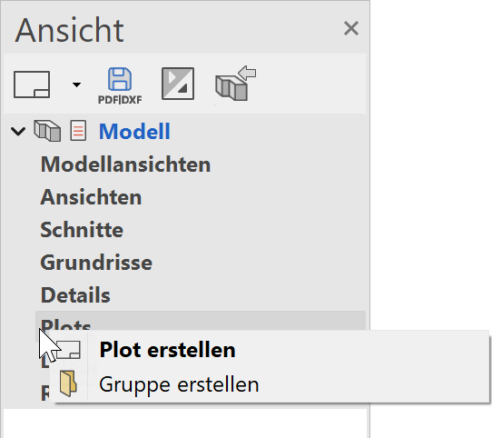
- Create a new plot and then enter the desired plot name. (e.g .: Example 08_pl)
or with the right mouse button
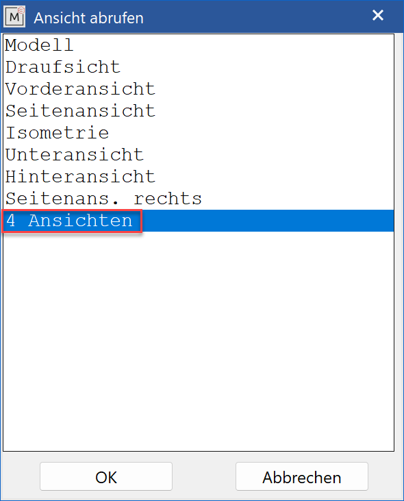
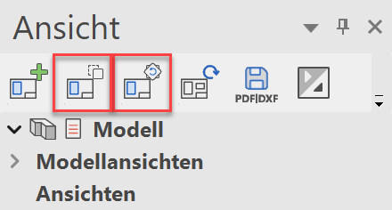
- Now click on INSERT VIEW INTO PLOT and select 4 VIEWS.
- The views can now be positioned using MOVE VIEW, ROTATE VIEW.
Tip
The individual views can also be positioned with MOVE SELECTION and ROTATE SELECTION.
- Set the main dimensions in the three views.