Project set-up
Open project
Before you can begin drawing a building, a new project must be opened.
In this case this is a simple building consisting of one structure with two storeys – ground floor and top floor.

Project settings
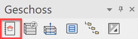
The project settings and project administration are set via the function PROJECT that is found in the Storeys Manager. Here you can open a new project or select an existing one.
Tip
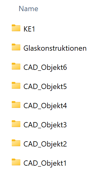
In Windows Explorer, a folder with the project name is automatically generated in the project path.
Structure settings
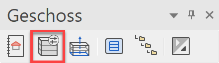
The individual structures and their storeys are managed under structure settings. A section through the building is defined with the relevant dimensions of the ceilings, floors and room heights.
Workshop
You begin by opening a project.
Open a new file > FILE NEW

- Open project mask and click on "New".

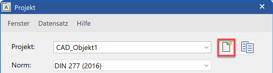
- Assign a project name.
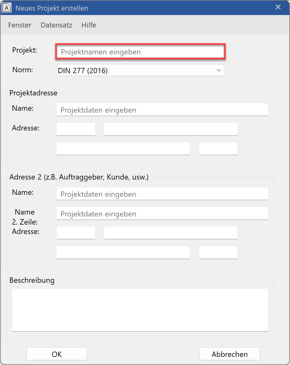
- You can add optional data (name, address, description) into the remaining fields of the project settings dialog window.
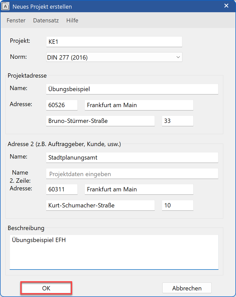
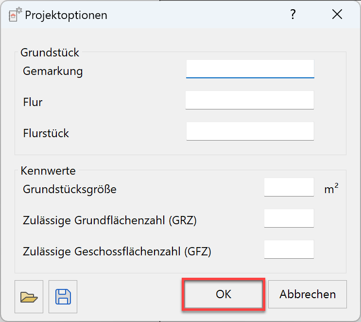
- As soon as the project settings dialog window is closed the project options dialog opens automatically.
If we already have important key values and boundaries for our property, we can enter them here. These will be automatically compared to the calculated values of the building model, and ELITECAD will inform us of any specific values that exceed them. In our case, the fields will remain empty and we confirm the dialog.
Click on again to edit the structure settings.
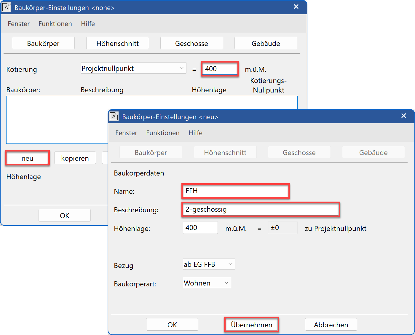
Set the height marking to Project null and its height: 400.
Click on NEW.
Enter the name, the description and the height of the structure. - Press
 to save the structure data.
Tip
In addition to the usual
 , there is an additional command on the screen which saves your entries but does not close the screen.
The also saves the entries but closes the screen. In this case, the screen can be accessed again from "File > Structure Settings". After setting, the screen switches from structure to height section.
The number of storeys and the relevant storey heights are defined here.
The heights refer to the clear room height.
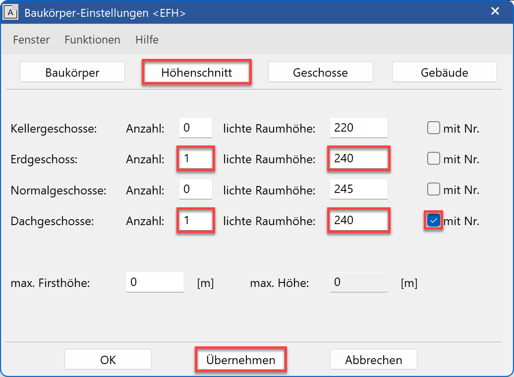
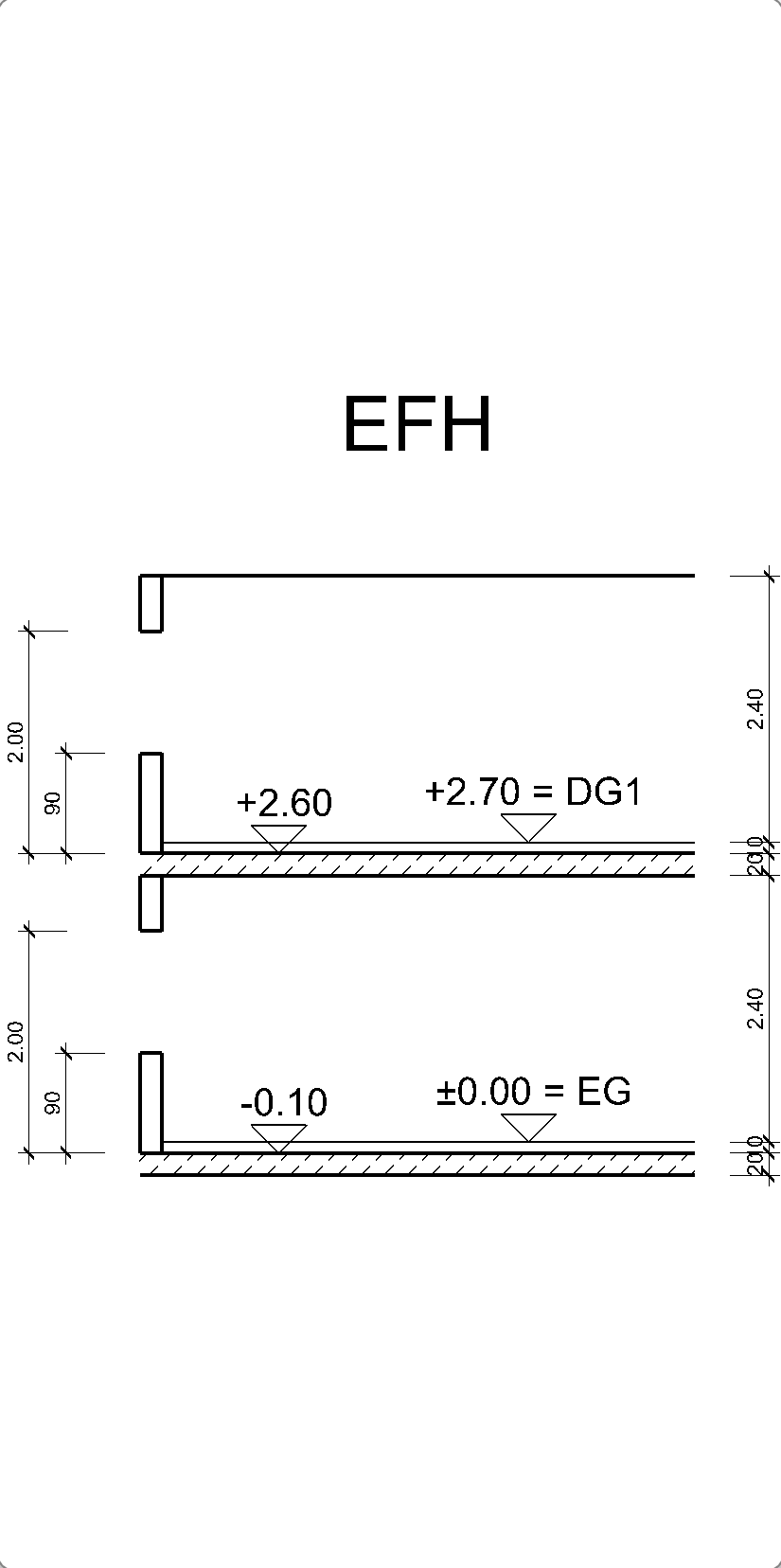
- As soon as you confirm the number of storeys with the button, the graphical height section appears on the right-hand side of the screen. Here it is very easy to check the values entered. Every change on the screen confirmed with is immediately displayed.
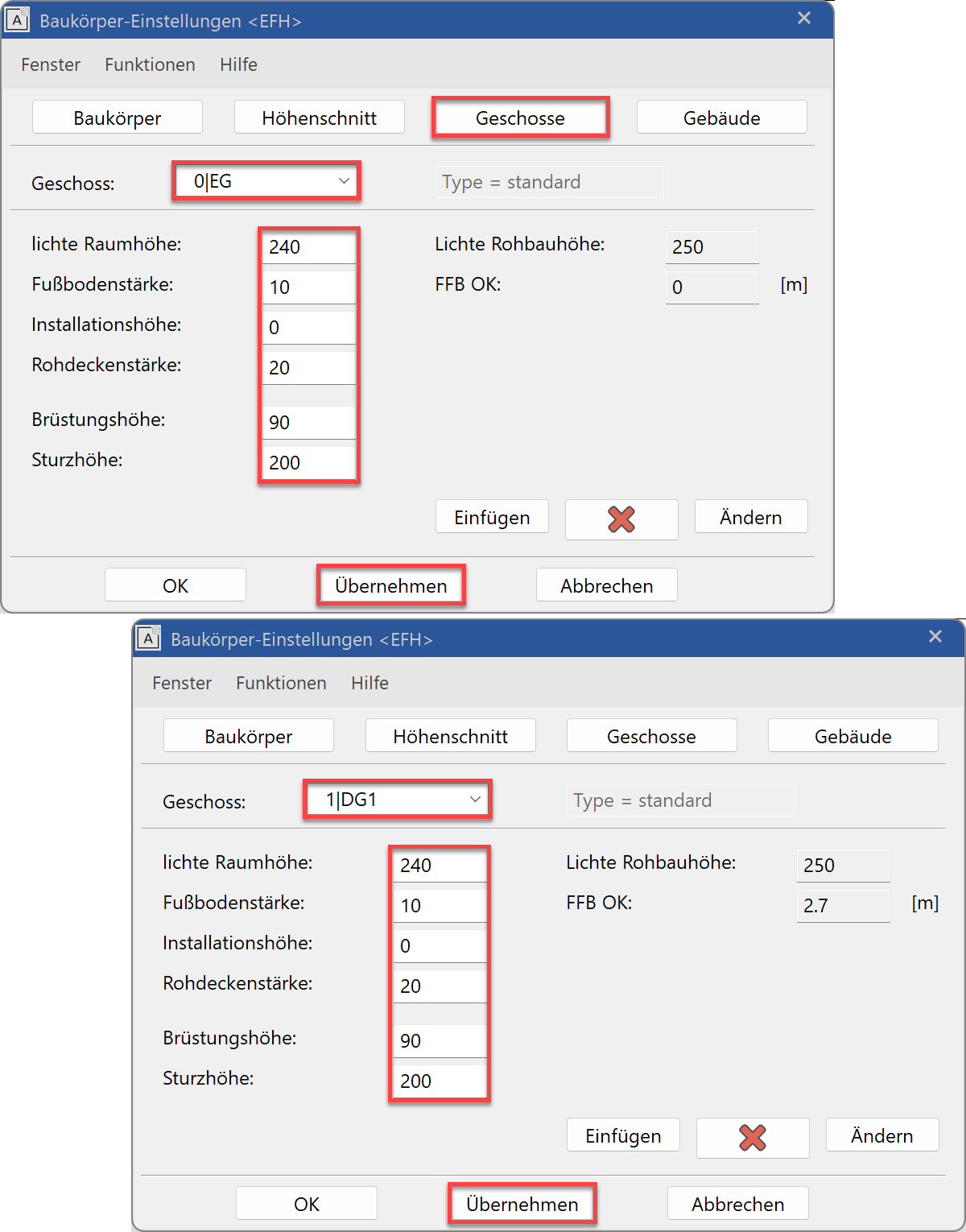
- Select the STOREYS tab.
Here you can make settings for each individual storey. To do so you must select the relevant storey in the "Storey" field, make the settings and then press before switching to the next storey.
Add the values shown to the ground floor:
- The rest of the information on the Structure tab is additional information about the construction but has no effect on subsequent entries in 3D.
Before you leave the screen with and , the height section must be checked again.
Tip
If you create a new project, do not enter special characters for the project name (exclusion: dash “-“ and underline “_”) and the length of the project name should not exceed a maximum of 80 characters.
Tip
The "with no." option should be activated if the quantity of the relevant storey type is only one and the option exists that in the course of the project other storeys of this type to be added to the height section.
Tip
The information is used as a basis for creating building elements such as walls, ceilings, windows, stairs, etc. The height information must be defined in such a way that they apply for the majority of the structure. Individual components can still exist at other heights.
Presettings
Before you start drawing, you should check the settings in the status window.
Workshop
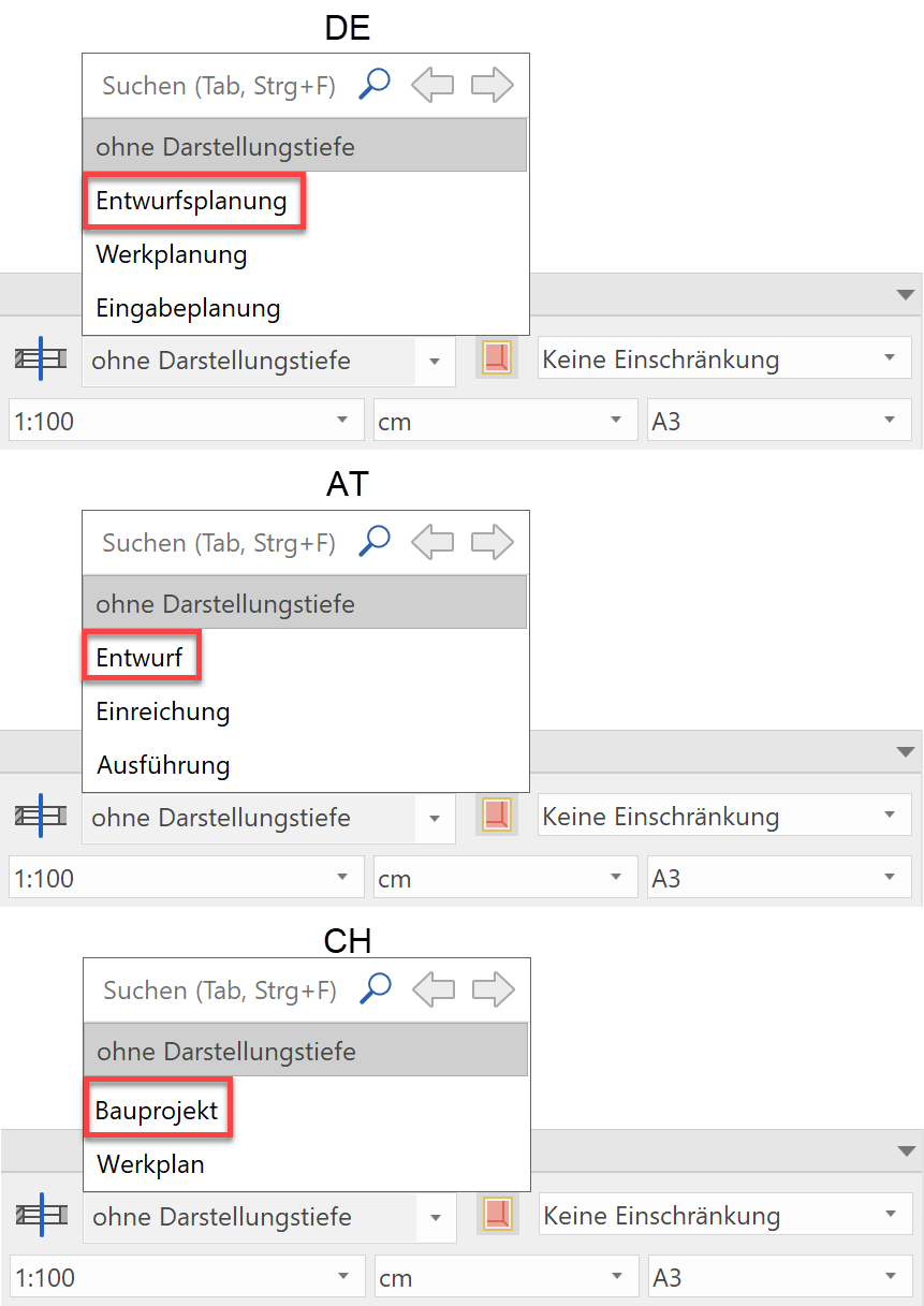
Representation level
Set the representation level to construction project.
Tip
Walls, doors, windows, etc. can be displayed in different representation modes. A representation level controls the level of detail of the different components.

Scale, unit, page format
Set the Scale, the unit and the page format to the following settings:

Storey
Select the storey in which you wish to start drawing.
To do so, open Storeys manager and left-click on the ground floor. The icon turns blue to indicate that it is active.
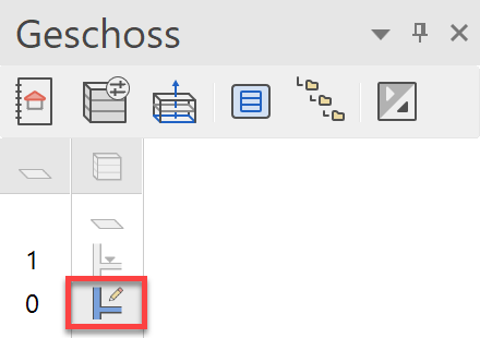
To open the Storeys manager:
Menu VIEW > WINDOW > STOREYS or Ctrl+2