Interior GF
Auxiliary lines
You will now draw the auxiliary lines to define the most important auxiliary lines of the inner walls. Some auxiliary lines pass through the middle points of the edge or are located in the centre between two points. Thanks to the snap functions, a skilled drawer can save themselves some tedious calculations.
Entry mode
In the property bar, a distinction is made between two entry types that only apply if there are multiple values. The individual values must be separated by a comma.
Relative parallel distances

The distances are reapplied from every auxiliary line.

Absolute parallel distances

The distances are always transferred from the element that was originally clicked on.

Workshop
- First, draw a vertical auxiliary line in the axle of the structure.


As soon as the capture symbol Middle of element appears, you can set the auxiliary line.

- Now transfer other auxiliary lines with a parallel gap to the first line. The auxiliary lines are transferred to the side that you click on with your cursor.

 > P1
> P1
 > P2
> P2

- Supplement the horizontal auxiliary lines in the same way.

- Use the CIRCLE BY RADIUS function to create a circle option. Enter the radius in the property bar > 80. In addition, the circle is tangential to the two auxiliary lines. When you select the auxiliary lines, the snap symbol To element must appear and the cursor must be on the side of the auxiliary line that is shown.


Inner walls
The walls are defined by an axis. If changes are made to the thickness of a wall, the change will be re-transferred from the axis. For outer walls the axis must be located outside; for inner walls it is less important on which side the axle is located. As a rule, e.g. in staircases or corridors, the axis can always be created on the inside.
Workshop
Create the walls on the ground floor.
- Select the CREATE WALL function and enter the following settings.


- In the Input Assistant, the drawing function Polygon is selected as standard.

Create the inner walls. To finish a wall, click again on the end point.
Start point > P1; End point > P2 double-click; Direction > P3

- To draw the curve for the inner wall with the rounded corner, you must select the circle function Curve over 3 points*.


- Create the rest of the inner walls.

- Delete auxiliary lines.

Erklärung
Delete auxiliary lines
The function DELETE ALL AUXILIARY GEOMETRY deletes all of the auxiliary lines.

Doors
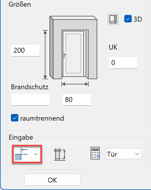
The level of detail of the doors depends on the selected representation level. The door main dimensions such as width, height and threshold can be modified directly in the property bar. In the door parameter dialog, you define whether the values are transferred as raw or finished.
| Finished clearance | Gross clearance |
|---|---|
|
|
 |
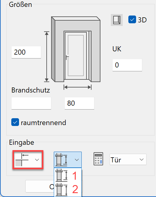 |
Workshop
Create the doors with the type "Standard".
- Select the CREATE DOOR function and check the settings.


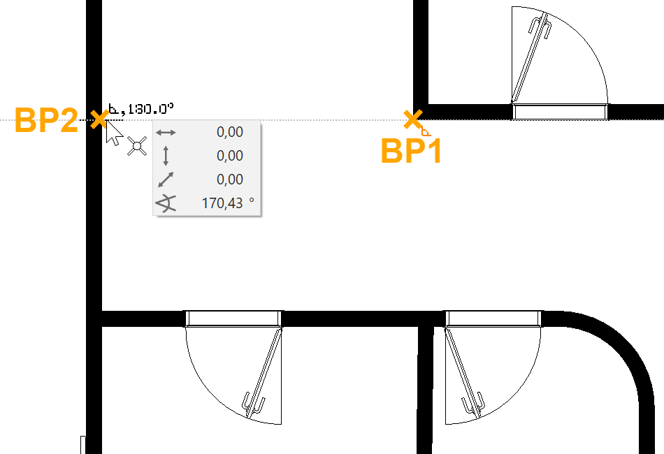
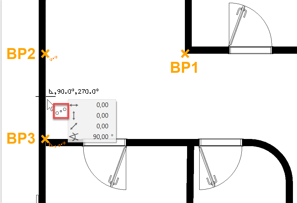
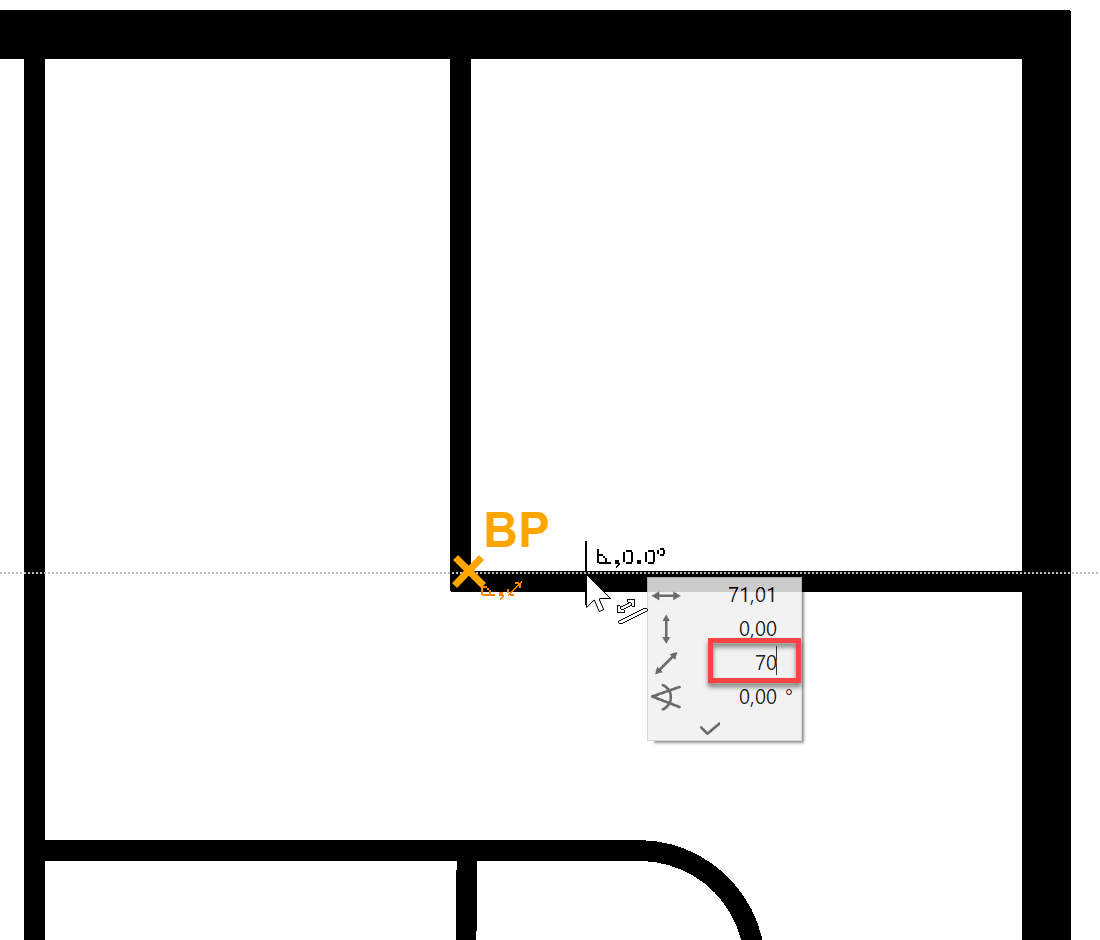
- Apply a temporary reference point RP, move the cursor to the wall and enter the distance of 70 cm.
You can now define the placement with the mouse pointer. The door moves either to the left, to the right or to the centre of the positioning point PP.
Left-click to place the door at the selected position.

- Now add the remaining doors. The outer door is located in the centre of the wall and is 90 cm wide.


- Sliding doors
Select the type "Sliding doors" and enter the following settings.

Place the sliding door a distance of 20 cm from the corner and locate the sliding doors in accordance with the template.
Model display Floor plan 

- Cancel the function with Esc.
Edit / move AR-Object
An incorrectly placed AR-Object can be very easily modified or repositioned later on.
Workshop
The opening direction of a door is to be changed and the door must be moved in the wall.


- Change the door opening type.
The easiest way to select the door is to click on the curve > P1. Handles are assigned to the door and the property bar is displayed with the settings for this door. In addition to the dimensions, modification functions are also contained in the property bar.
Select the function MODIFY DOOR STOP.


As soon as you select the function the door is ready for the change. Redefine the placement with the mouse pointer > P2.
- DieThe door is still active (magenta, property bar and handles). It can now be moved directly.
Move the cursor on the door handle until the display symbol on the cursor changes to a double arrow. Select the handle > P1.

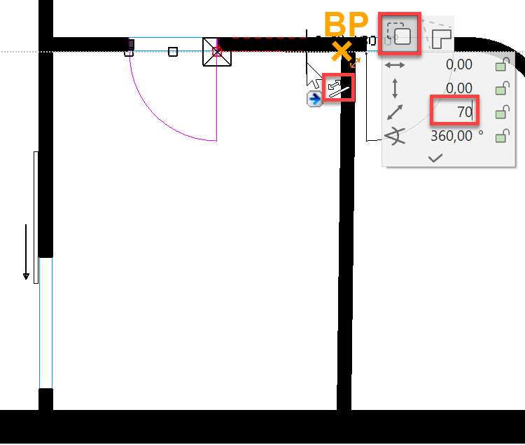
Select the move option (predefined as standard) and, using a temporary reference point, reposition the door with 70 cm from the room corner.
- Cancel the function with Esc.
- Edit the outside door.
Select the outside door with a click and change the threshold height to 13 cm.

- Save a work copy with Ctrl+W.
Wall opening
A wall opening is a wall cutout without stop parameter. Later on, the wall opening can be reselected or edited using the diagonal blue line in the floor plan.
Workshop
Set a wall opening in the middle of the corridor. This will teach you how to use the capture mode in the ideal way.
- Select the CREATE WALL OPENING function and check the settings.


- The wall opening is to be aligned towards the centre of the corridor.
First, set the temporary reference point RP1 with the help of which you can set the reference point RP2. You can reach the middle point by setting the reference point RP3. Set the opening into the wall.