Stairs
Various stair types are parameterised and can be entered into parameter dialogs.
Workshop
Create a dog-leg concrete stair with a landing.

- Open the stair dialog.

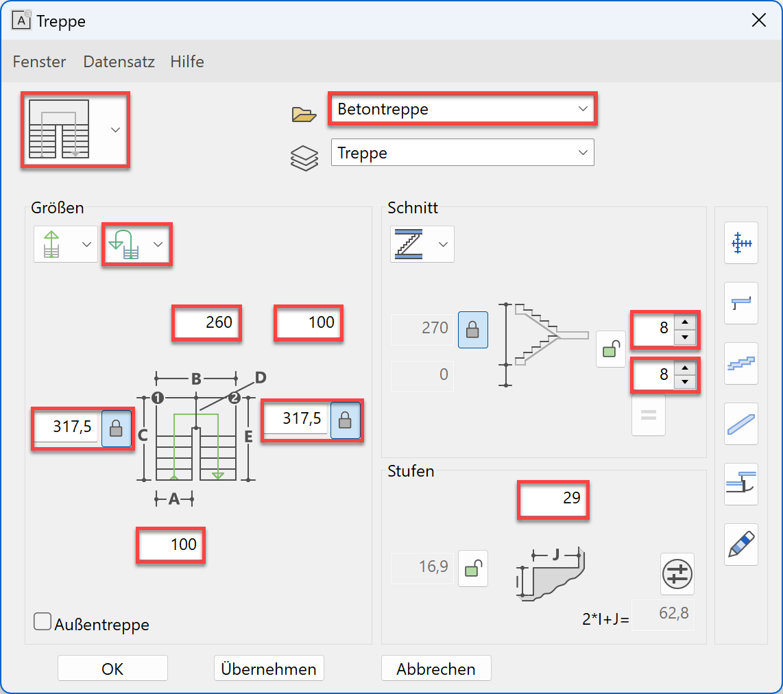
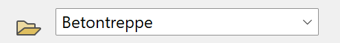
- Select the data record "concrete".
Select a dog-leg stair.

- Check whether the height (storey) reference is set.

The locked value is automatically the storey height, the gradient is calculated.
Change the number of steps to alter the gradient.
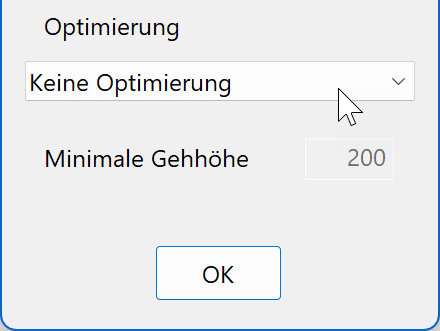
- Switch the limit value parameters to No optimizing.


- Enter the rest of the values in the dialog.
- Fix the length for value C + E.

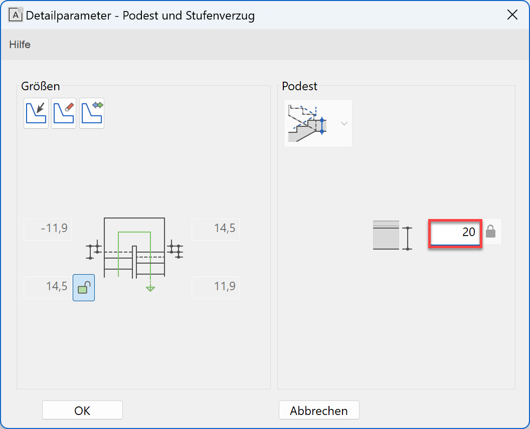
- Select Landing and step winding

Check the alignment of the exit and entrance. If the stair lengths are fixed, the values in the dialog are locked.
Change the thickness of the landing to 20 cm.
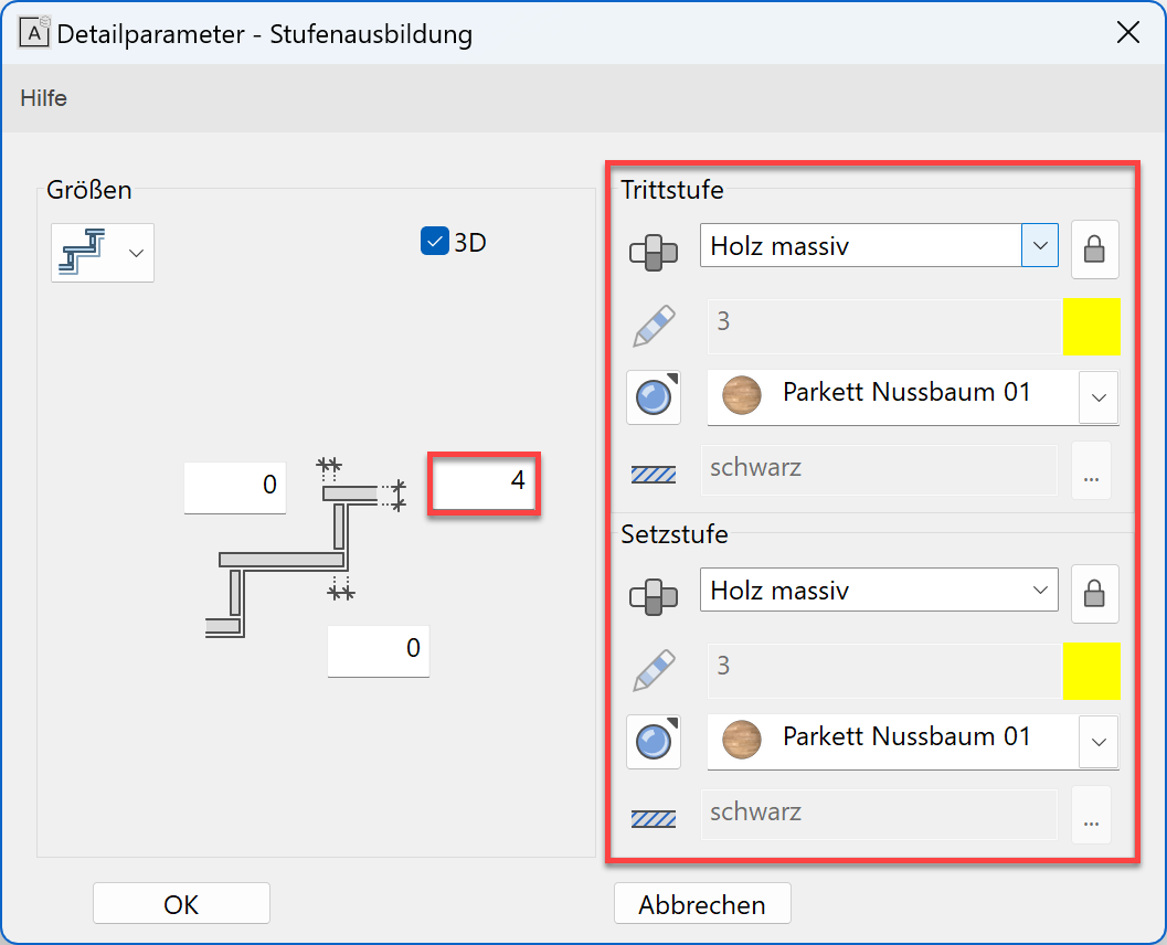
- Select step design

Enter the values for the covering
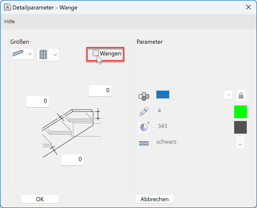
- Select stringer

Switch off stringer
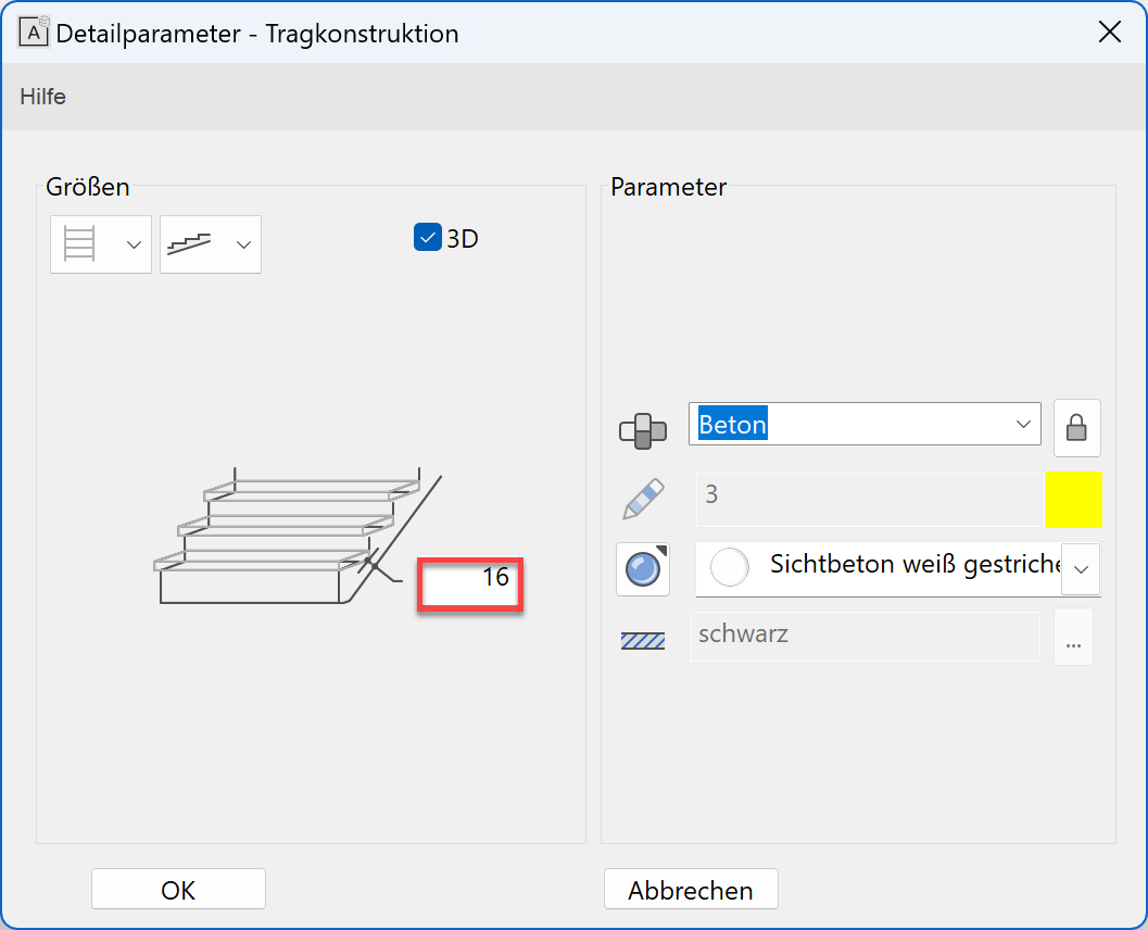
- Select load-bearing construction

Enter thickness of the tread construction
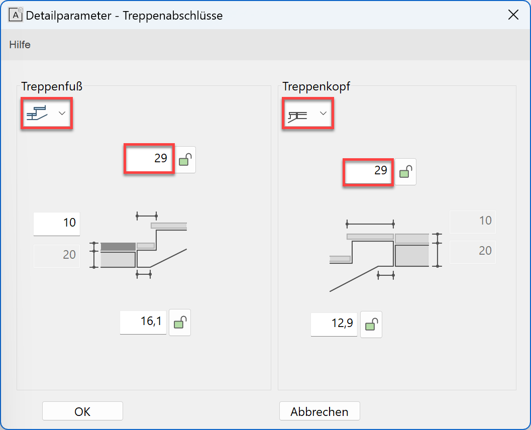
- Select stair ends

Select entrance and exit type and set exit length to 29 cm
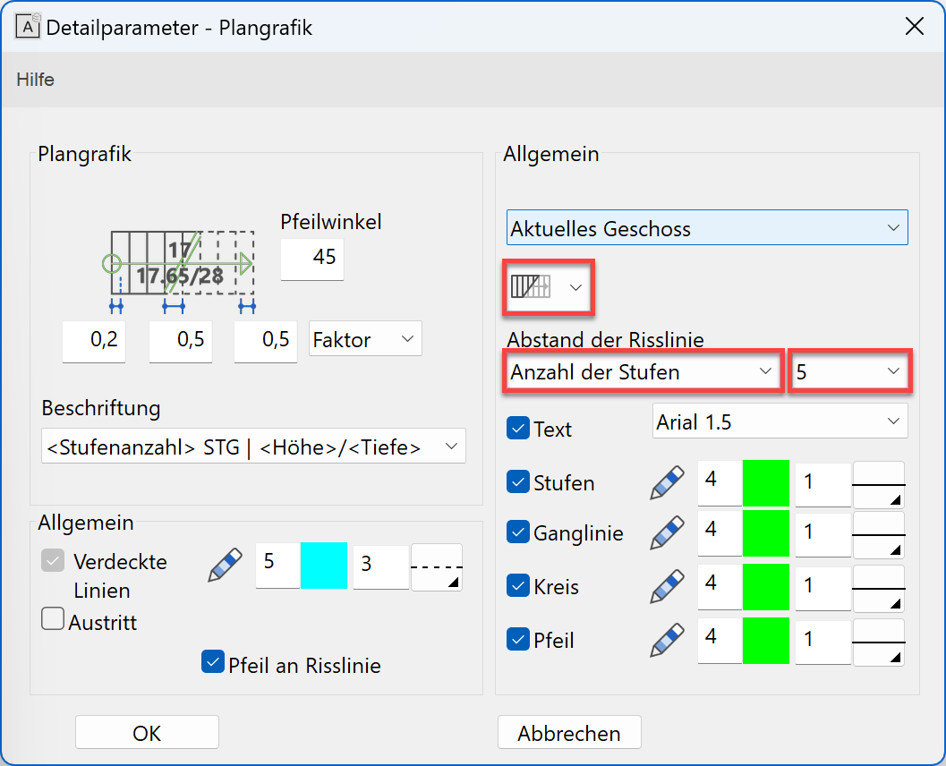
- Plan graphics of stair

Floor plan depiction "Top view of lower stair"
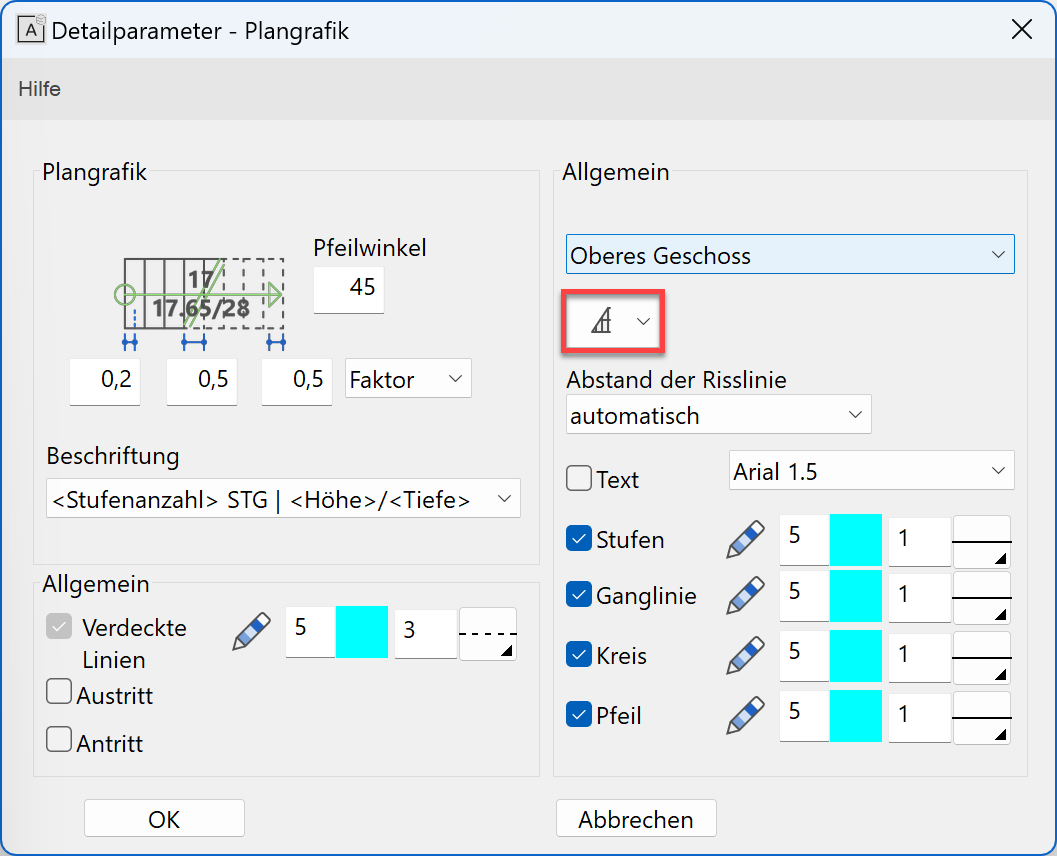
Activate floor plan depiction for upper storey
- Position stair in model
first point > P1; second point > P2; placement type > P3
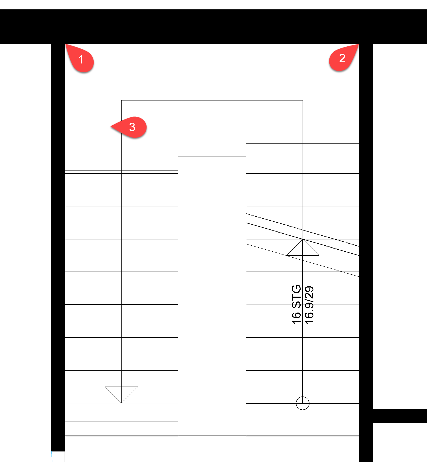

Click
to close the screen.
Tip
Under the geometry tab, you can see the two points by which the staircase is to be placed.

Stretch
In addition to the stretch function, the construction parts, elements and hatches can also be stretched using their handles.
Workshop
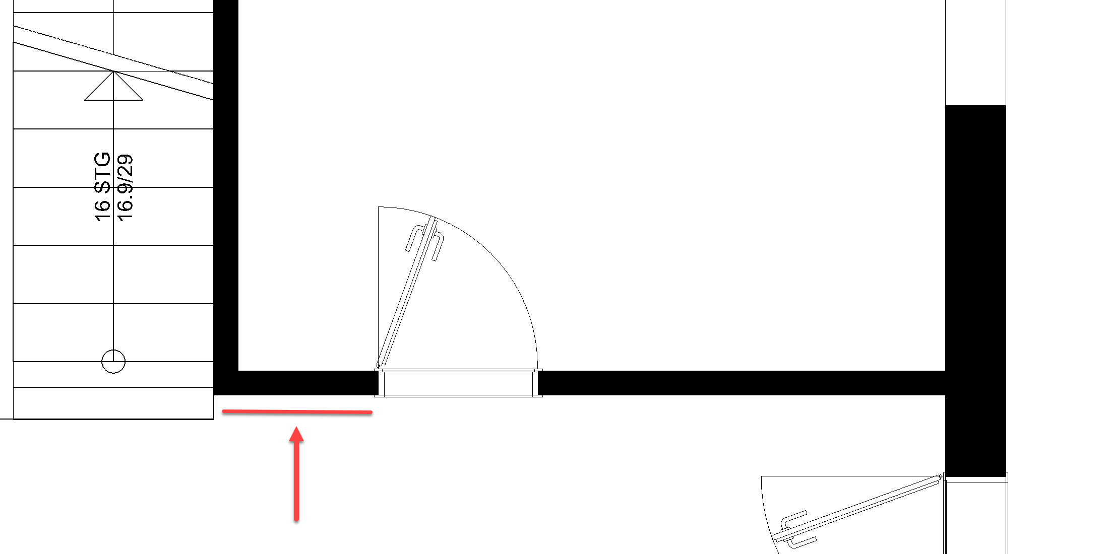
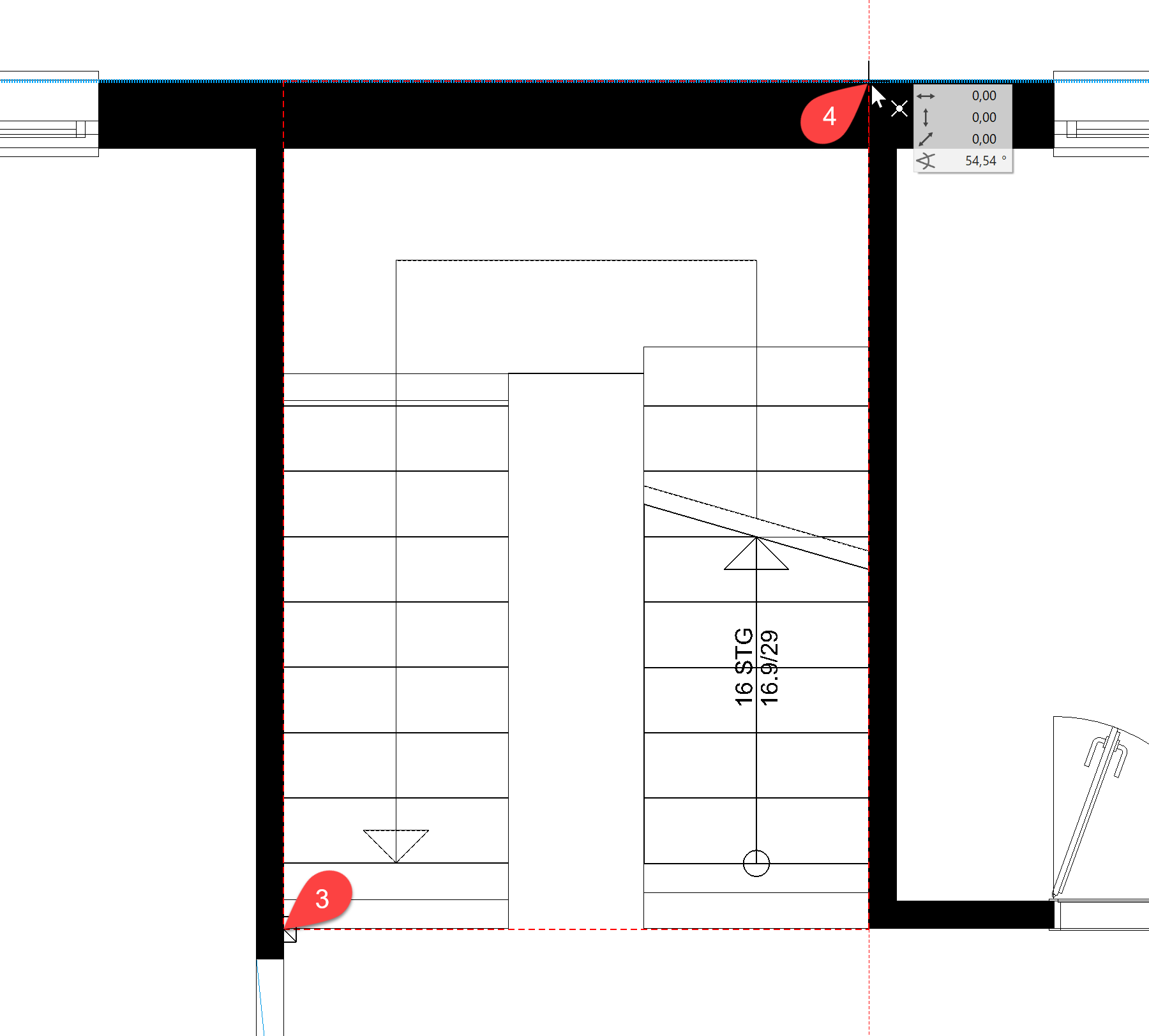
The wall must be stretched in such a way that the wall corner is flush with the staircase entrance.
- Select the wall. The wall turns magenta and handles appear on the axis. In addition to the handles, the wall can also be changed on the axes marked by a dotted line. These axes are knowns as the grippers.
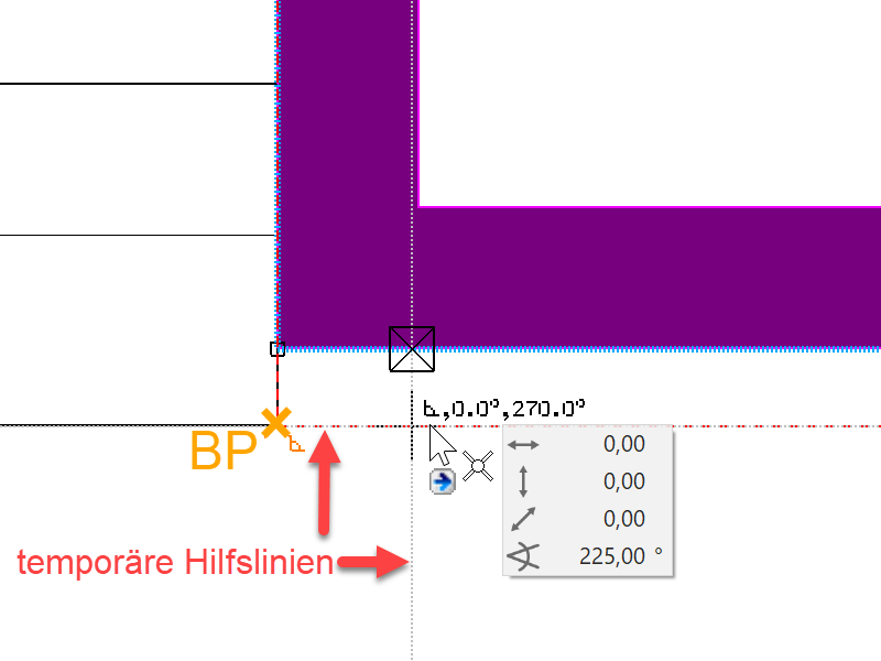
- Click in the corner on the axis (cursor symbol switches to double-arrow) P2. In the input assistant select the manipulation function STRETCH ELEMENT.

- Set a temporary reference point RP at the corner of the stair and move the cursor vertically below the point on which you selected the axis. Orthogonal help lines are created starting from both points on the section point of which you can set down the wall.

- Cancel the function with Esc.
Staircase opening in ground floor slab
There are a number of different ways in which the shape of a slab can be modified.
- Manipulation functions in the Input Assistant, applied to the slab contour
Used mainly for changes to the outer contour
- Change functions in the property bar are floor offset, edit slab contour or split slab.
![]()
![]()
![]()
Workshop
The ground floor slab is to be cut out for the stairwell. The new contour of the slab must match the red line. An auxiliary line is created in this example as a drawing aid. Similarly, you can just as easily use a temporary reference point.
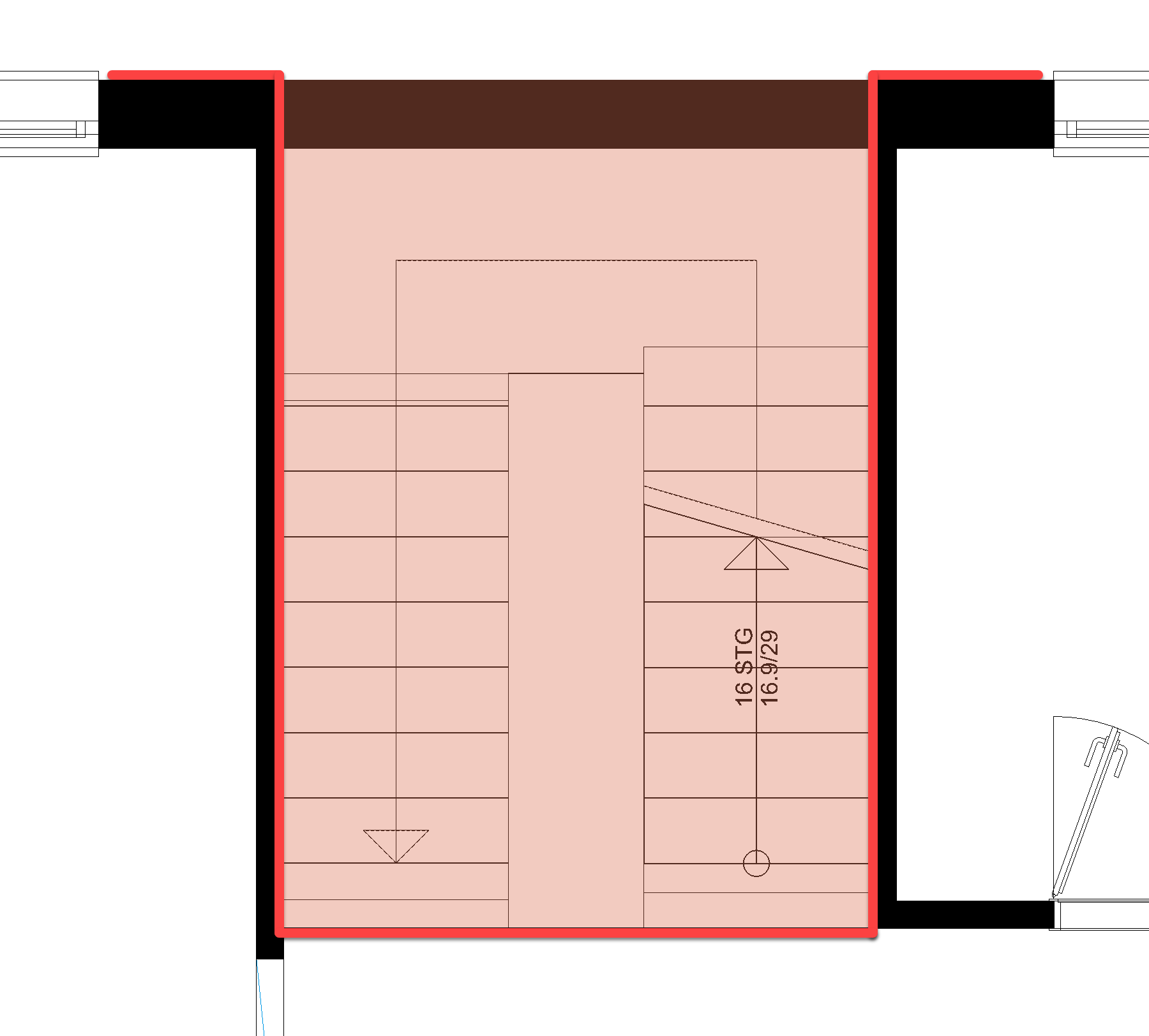
- Apply an auxiliary line using the function PARALLEL STRAIGHTS with distance 0 to the staircase wall P1.


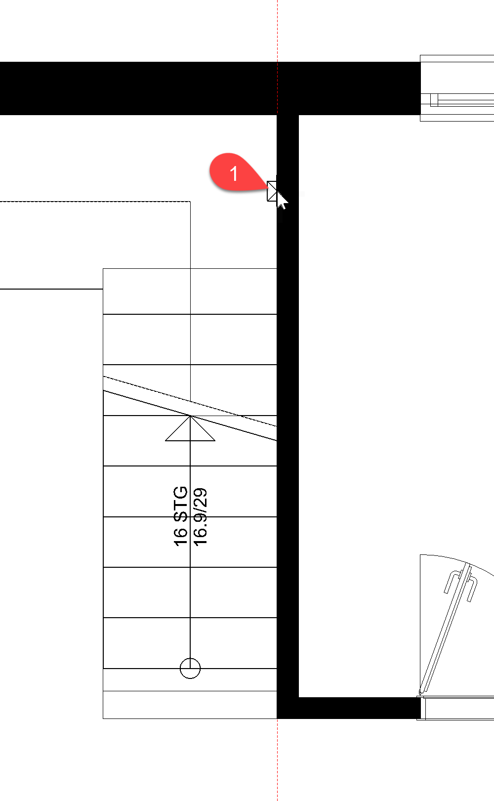
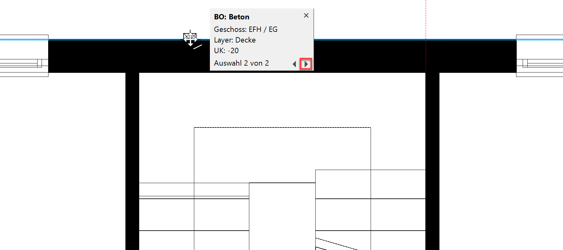
- Select the slab by clicking on the outer edge of the wall below which the slab contour is also located. The selection window with the number of options will be displayed. Use the arrows to switch between the selections to select the slab.

- Click again on the contour P2 so that the input assistant appears. Select the function REDUCE POLYGON.

The input assistant switches to the drawing functions. Select the function RECTANGLE.

Drag the rectangle up from the point P3 to point P4.
- To check, switch to the solid design model and then back to the wire model.

 or use the key combination Ctrl+D
