TF windows
Work plane on surface
With ELITECAD, you can set the windows both in the floor plan and in the view. The work plane can be rotated as required or be set on surfaces.
However, working on a wall surface soon becomes messy if the entire model is visible. For the sake of clarity, when working in the floor plan you can hide storeys.
When working in the view, the function CLIPPING is a useful tool for modifying the area of visibility.
Workshop
To enable a window to be set directly in the façade, the work plane must be placed on the facade.
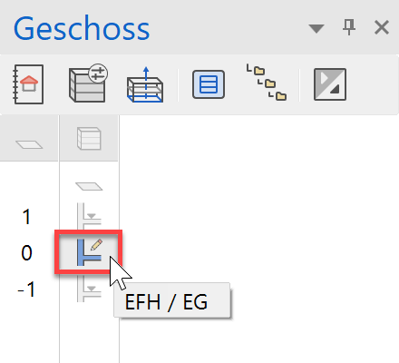
- Select the ground floor as the current storey.
- With the function WORK PLANE ON SURFACE, set the work plane on the facade.

For point P1, click on the facade.

- Switch CLIPPING on. On the clipping screen, change the upper and lower clipping planes to 70 cm and activate it. The clipping planes can still be altered by dragging the yellow circles using the mouse.


Explanation
The clipping function can be used to reduce the visibility of the model.
In the Z direction (perpendicular to the work plane), the visibility is defined via distance information, e.g. 70 cm.
The data is only hidden on the screen. This means that the function cannot be used to create a view or section. - Set the work plane to perpendicular and switch to the wire model.
Ctrl+Space, Ctrl+D

- Zoom into the following image section.
Mouse wheel or Shift + centre mouse button, Ctrl + centre mouse button.

Set window in view
If the wall reference is contiguous between multiple storeys, a window can be drawn that spans multiple storeys. The window appears in the floor plan of both storeys.
Workshop
On the facade, set a window covering multiple storeys by increasing the size of the window in the facade.

- Draw auxiliary lines for the window.

An auxiliary line is created directly on the selected line with distance 0.


- Position the window.
Open the window dialog and enter the below settings.


- Draw the window from bottom left P1 to top right P2.

- Cancel the function with Esc.
- Switch CLIPPING off.
- Reset the work plane with the function RESET WORK PLANE.

- Delete the auxiliary lines.


Windows in the top floor
Like walls or slabs, windows can be copied individually to a current storey.
Workshop
Copy two windows from the ground floor to the top floor.
- Switch to the solid model Ctrl+D.
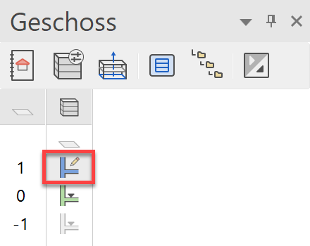
- Select the top floor as the current storey.
- Rotate the model to the position shown below.
- Start the function COPY TO CURRENT STOREY.

- Click on the windows P1 and P2.


- Switch back to the wire model Ctrl+D.
Copy / mirror windows
Instead of constantly having to reposition windows, existing windows can be copied and also rotated or mirrored.
Workshop
- Switch the top floor < > visible alone. (double-click)
- Switch to the origin view Ctrl+Space.
- Select the window to be copied (P1) (if the selection list appears, switch to the window).


- Select the function COPY SELECTION.

- Determine point P2 as reference point. The window is now "attached" to the cursor and can be repositioned. At the same time, the property bar with additional options is shown. Mirror the window vertically.

- Position the window in the new corner P3.
- Cancel the function with Esc.