Create views
Generate floor plan views
Until now you have performed all functions in the 3D model. The corresponding floor plans, views and sections can be created from the model.
Workshop
Generate the 2D floor plans.
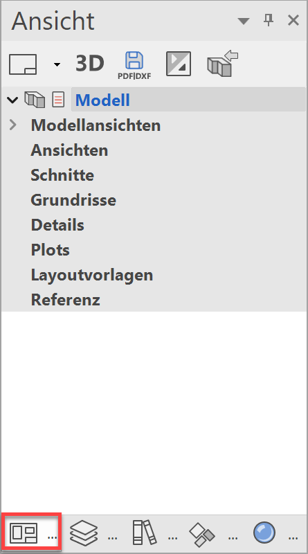
- Access the views manager. If the views manager tab is not visible, it can be accessed using the key combination Ctrl+5 or from the menu by selecting WINDOW > VIEWS….
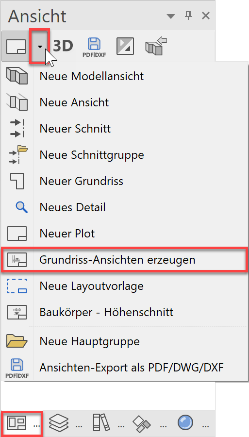
- Create the floor plans using the function GENERATE FLOOR PLAN VIEWS.

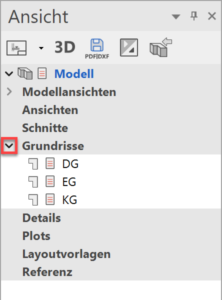
- The floor plans are listed under the title "Floor plans".
Define section
When defining the section, all of the relevant storeys must be visible. Storeys or individual layers can be hidden.
You can choose between simple, stepped or limited section control.
Workshop
Create a cross section.
- Check whether you are currently in the Design model view.
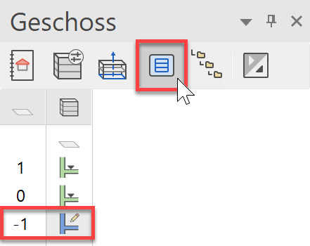
- Use the SHOW ALL STOREYS function to assemble everything and specify the basement as the active storey.
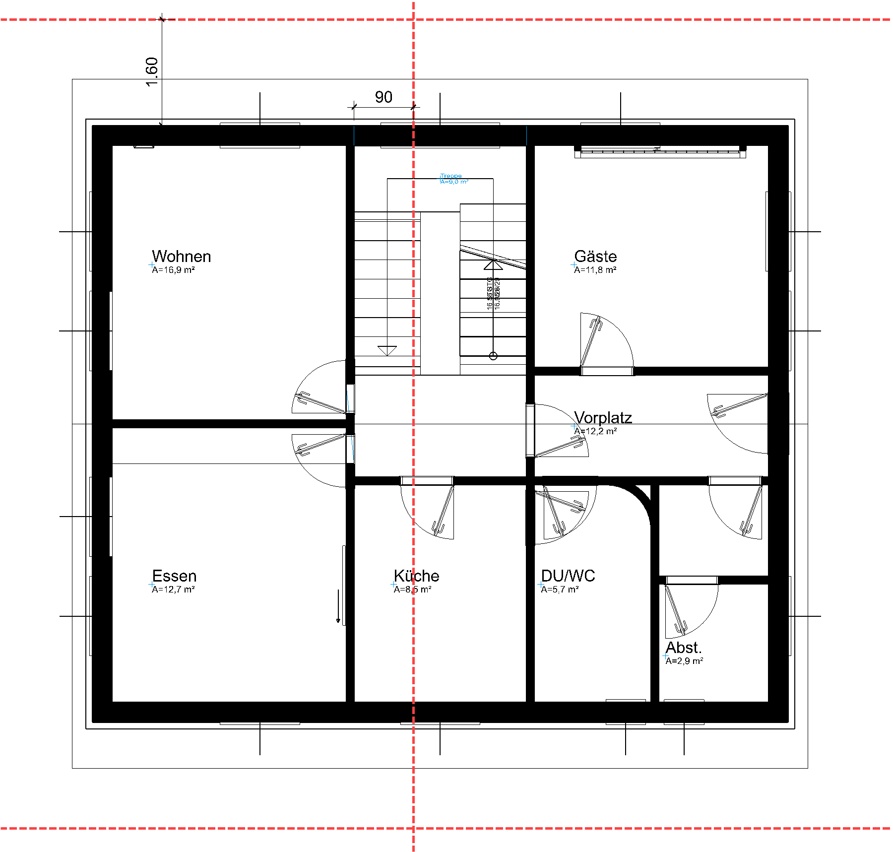
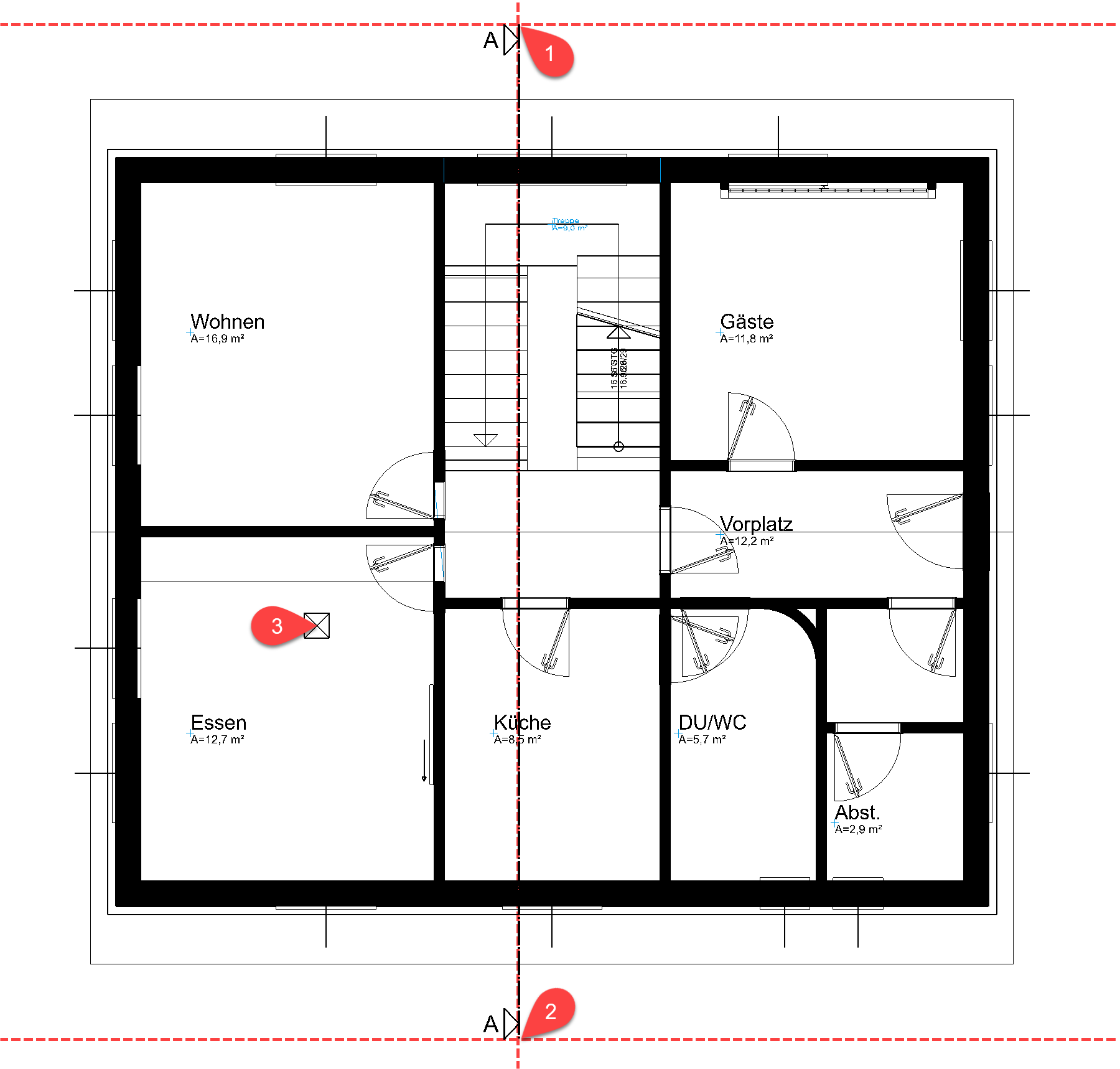
- Create an auxiliary line construction to set down the section line accurately.
Horizontal: Distance of 160 cm from the foundation slab on both sides
Vertical:90 cm distance to wall in staircase
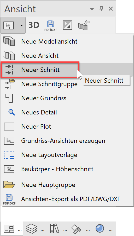
- In the views manager, select the function NEW SECTION.
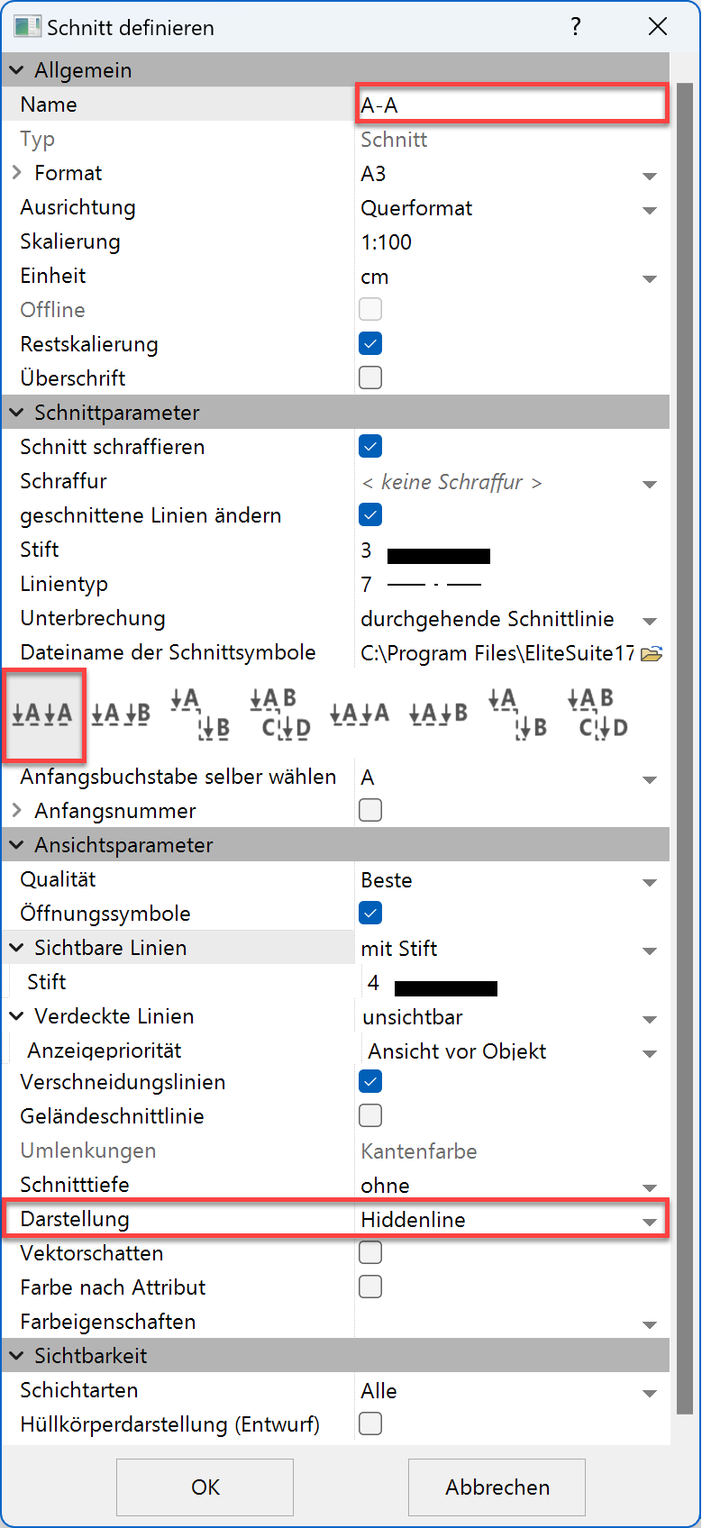
- Enter the settings for the section.
- Specify the points P1 and P2 for the section line.
Right mouse button:
The last entry determines the direction of the section > P3.
- Delete the auxiliary lines.
Tip
Do not place the section line exactly in the gable of a gable roof, but rather slightly offset.
The section symbol with the section line is very important for the CAD. When a section is updated the system refers back to the section line. The section line can be moved in the model to be able to respond to a change in the floor plan. What you must not do is delete the section line from the plan otherwise the section view will no longer have a reference to the model.
The section line should be displayed as a dotted line.
- Select section line.
- In the property bar, select the option Broken section line.

- Cancel the function.
The section line is only in the current storey; copy the symbol to the upper storeys.
- Select the section line.
- Specify the ground floor as "current".
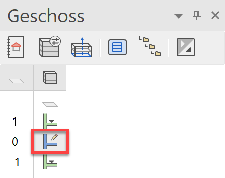
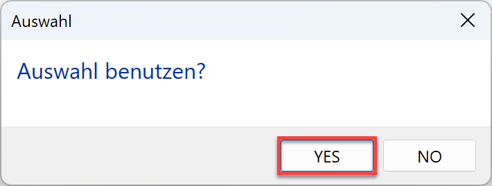
- Start the function COPY TO CURRENT STOREY.

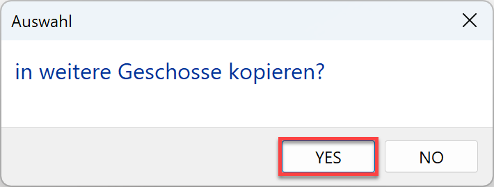
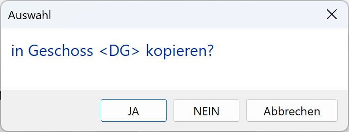
- Confirm the following three dialogue windows with YES.
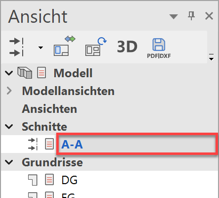
The section symbol is now located in all 3 storeys. - In views manager, select the section A-A.

The finished floor is not displayed in the basement and top floor because on these floors the rooms have not yet been labelled.
Tip
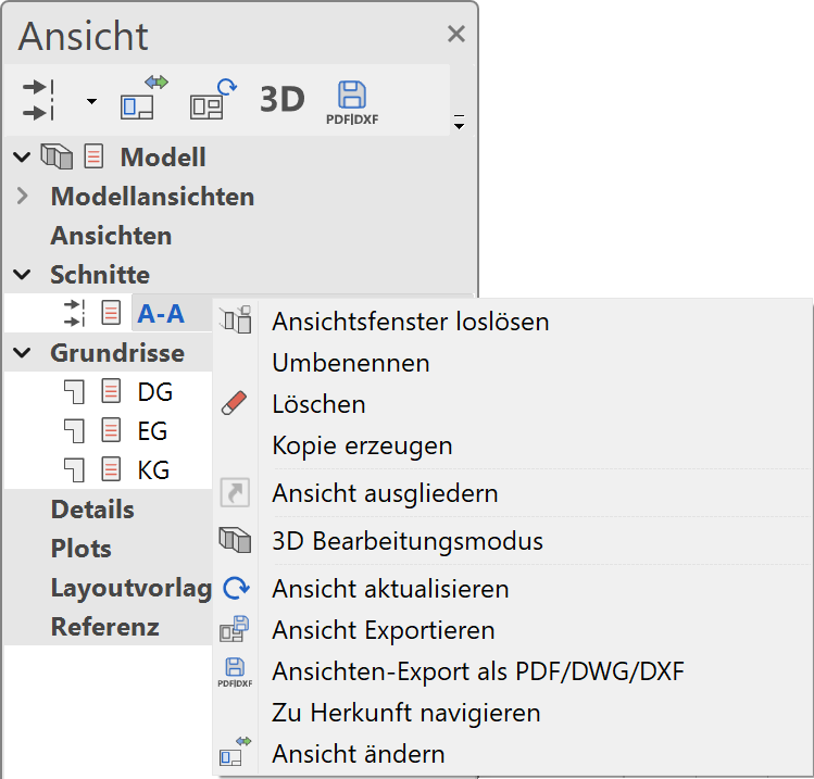
If you right-click on a title or a view in views manager, subfunctions appear.
The function DELETE VIEW deletes the view visible on the screen.
Define view
A view is generated from the model or from a model view. The current 3D view angle on the model is represented as a hidden line (visible lines) in 2D form in a view.
Workshop
Generate a south and a west view.
- Standard model views are available which automatically rotate the model into the correct position so that the façade views can be rendered.
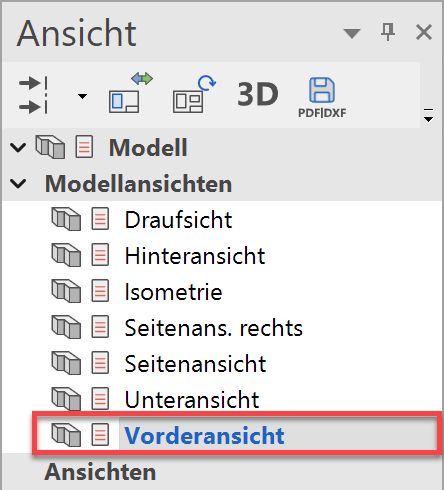
In the views manager, select Front view from among the model views.

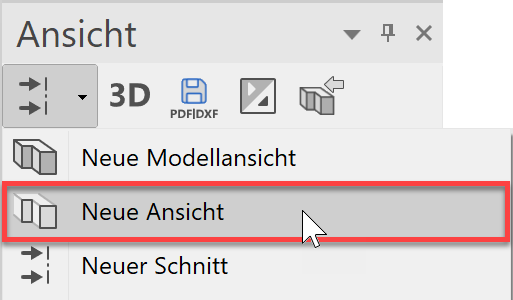
- In the views manager, select the function NEW VIEW.
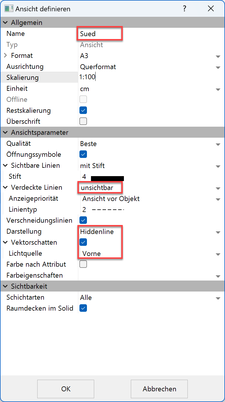
- Label the view South and enter the rest of the settings.
Die Ansicht wird berechnet. - Generate the west view.
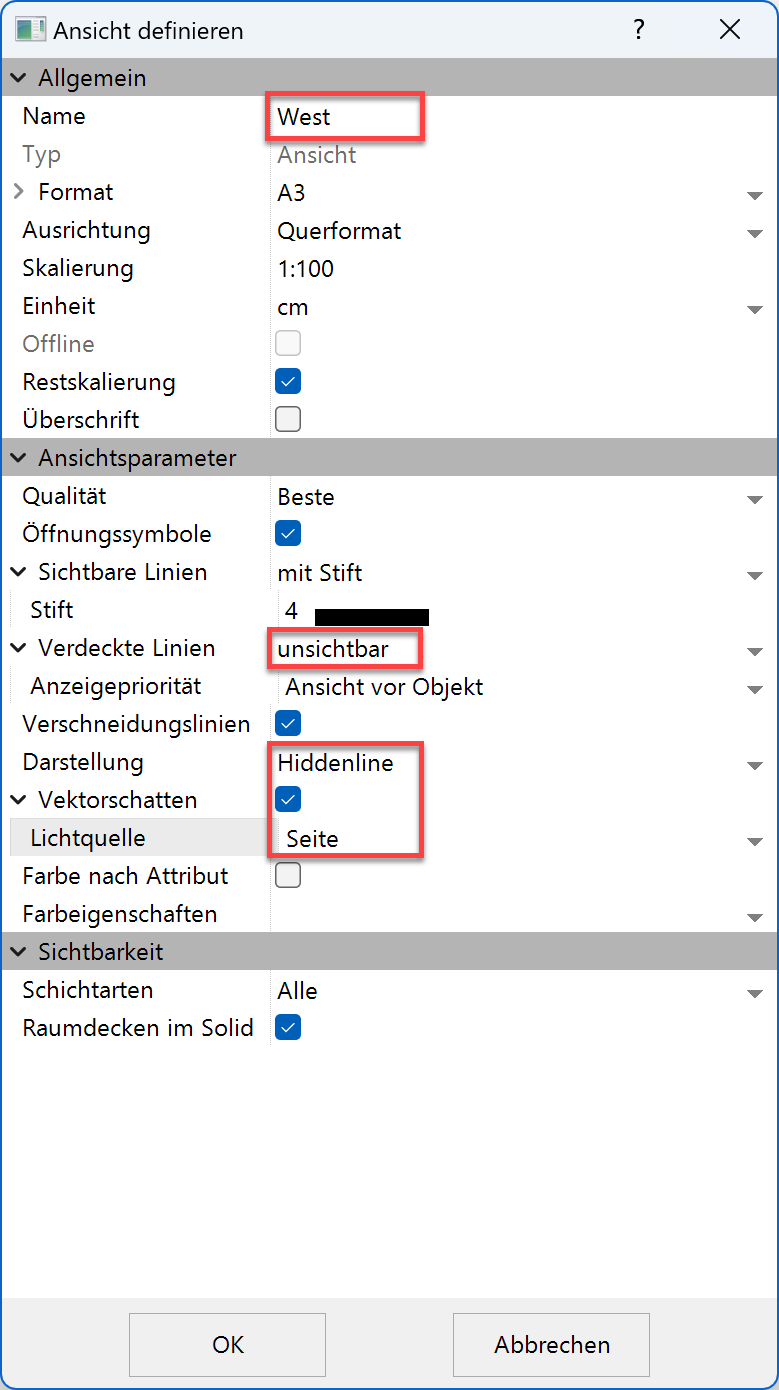
In views manager under model views, select the side view left and define a new view with the name West. For the vector shadow, use the light source Side view left.
- The two generated views are listed under the views.
South view West view 

If the option Öffnungssymbole is activated in views, these symbols will be displayed in the view.