Edit views
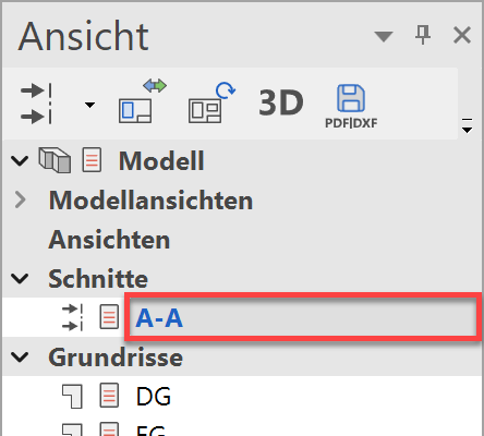
Edit Section
The section view is purely a 2D plan. Lines or segments can be deleted without hesitation in this view. Pen and line types can be modified.
A section view is uncoupled from the model until you refresh it to the latest version of the model using the UPDATE VIEW function.
Any newly added lines, dimensioning, trees, etc. are retained. If lines are modified or deleted, a "Deletion line" is automatically generated which hides the original line. The "Deletion lines" automatically create a separate layer.
Workshop
- First, load the section onto the screen.
- Delete the view lines of the concrete ceilings in the staircase using the function DELETE ELEMENT.

Delete the red lines.


Explanation
In place of the black line, the programme generates a blue deletion line that is not printed. The deletion lines should not be deleted because they automatically delete the view lines when the section is updated.
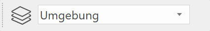
- Add a light shaft and the terrain lines to the surroundings.
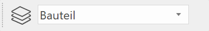
Use the auxiliary lines for the preliminary sketch and do not forget to set the correct layer, the line type and the pen type before beginning to draw.
Light shaft:

 > View lines
 > Section lines
Terrain:

- The floor finish is missing from the top floor and the basement.
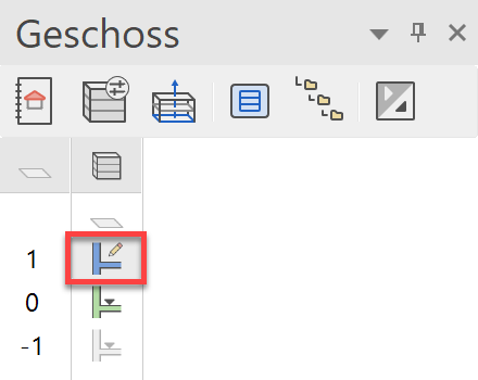
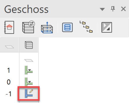
In the Storeys manager, double-click on the top floor to switch back to the model and simultaneously show it alone.
Tip
When you select a storey, the system switches back automatically from section/view to the design model.
- Draw a room separator between the staircase and the corridor > P1-P2.
To complete the room separation, select the end point P2 again.


- The last step projects into the door opening. The wall and the two doors must be moved.
First select the 3 objects concerned:
Hold the Shift key gedrückt and select the two doors and the wall.

- Select the function MOVE SELECTION.

- Move the door reveal to the edge of the last step. Select the point that you wish to move (door reveal), then specify its new position (edge of last step).


- Cancel the function. The door reveal is now level with the last step.

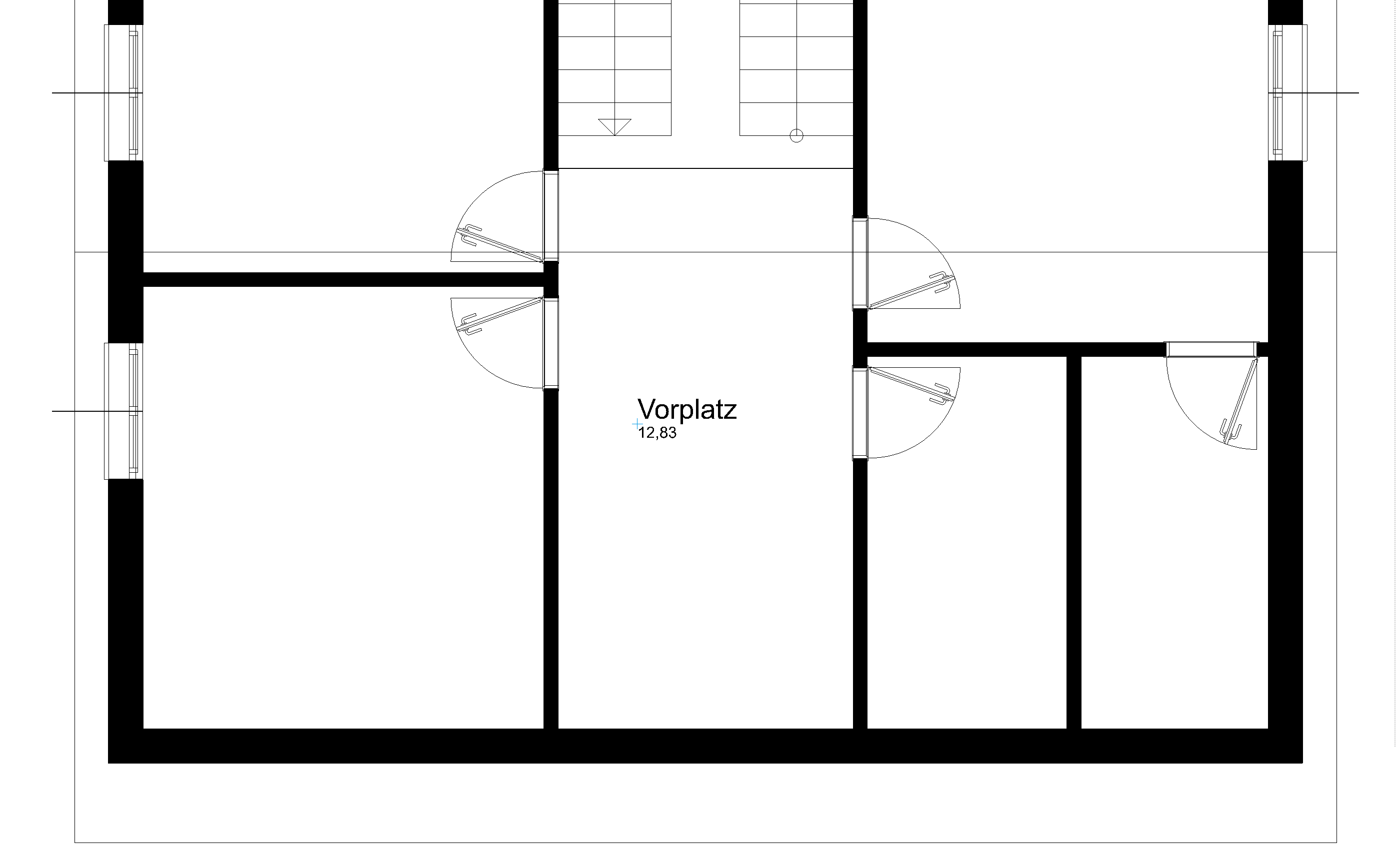
- The preparations are complete. The room label for the hallway can be positioned.

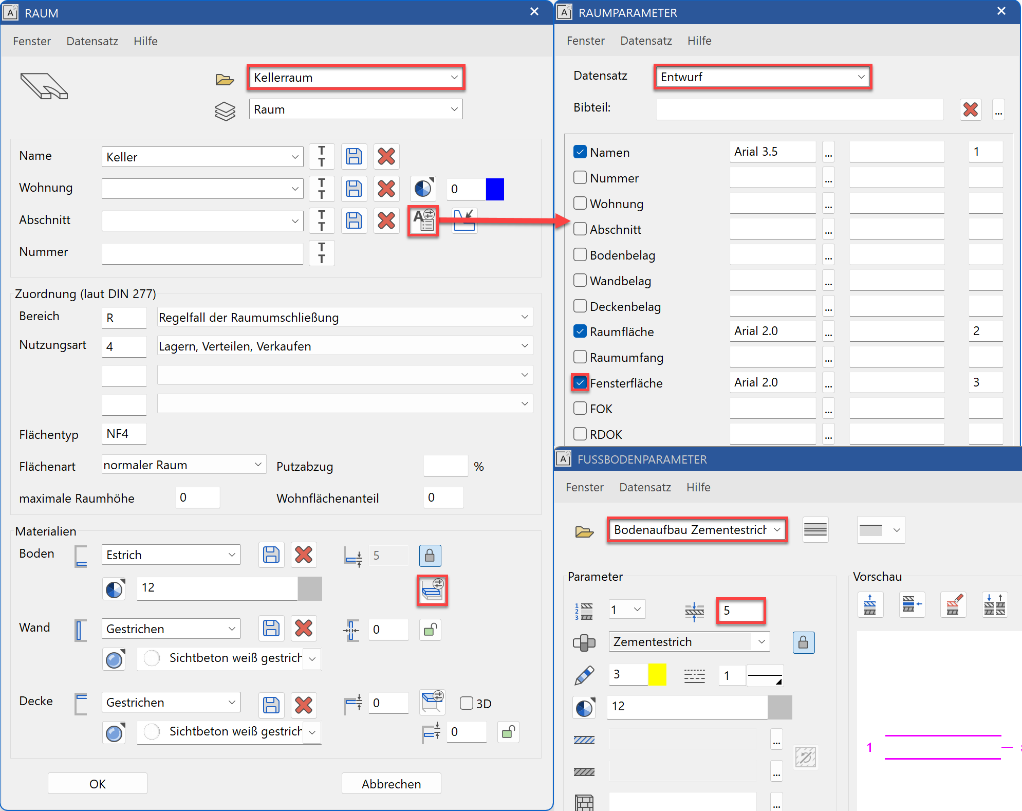
Select the room type Living area and change the room name to Hallway.Remove the entry "Window area" from the room label in the labelling parameter dialog.
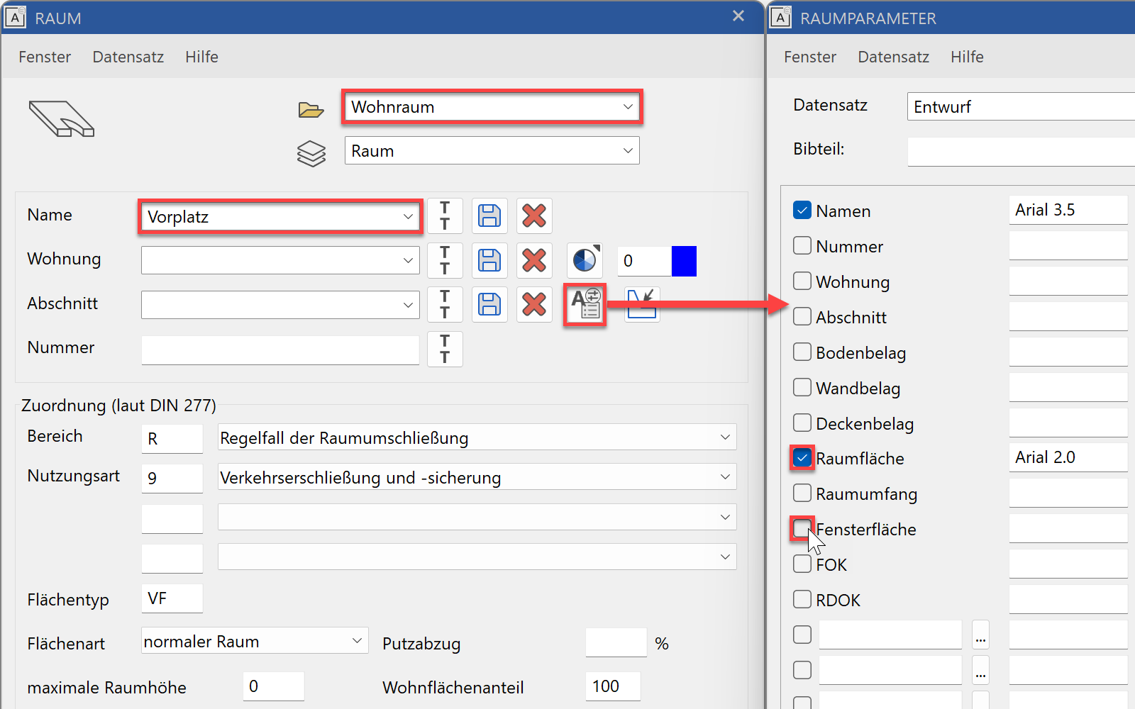
Apply room label.
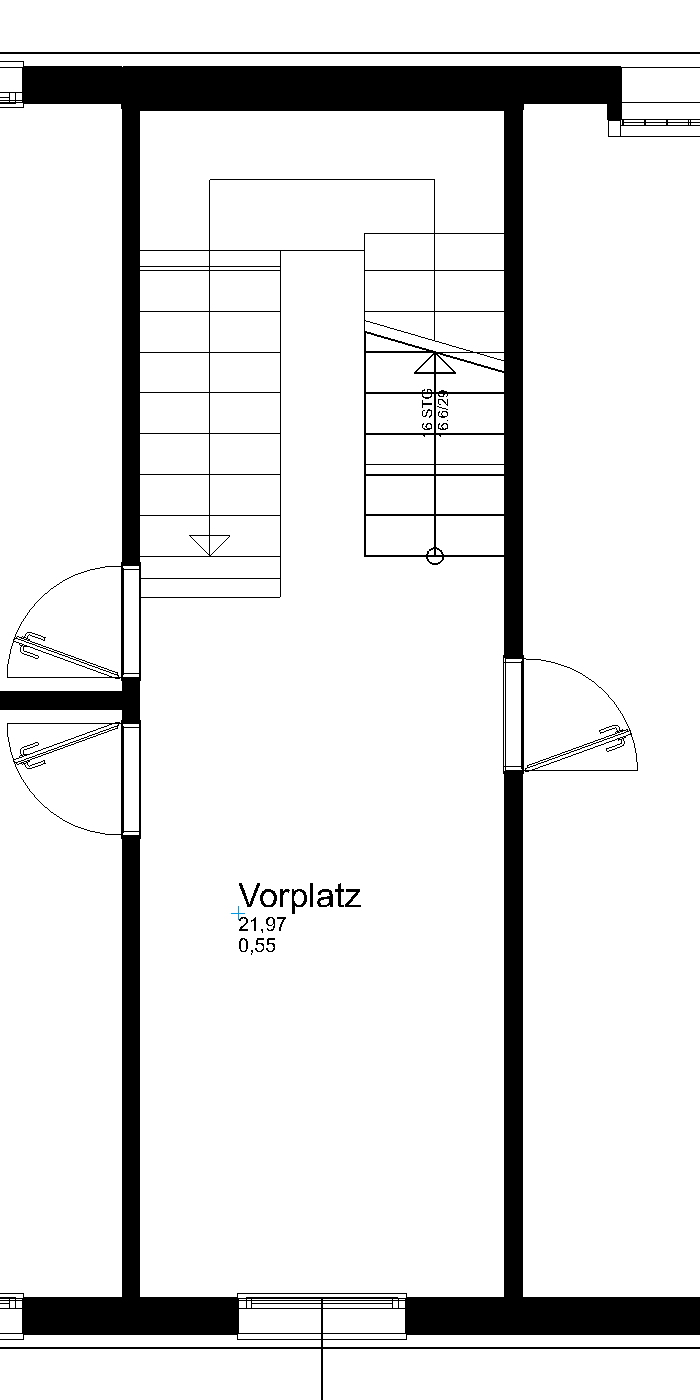
- Switch to the basement and apply a room label there as well. Room separation as found on the top floor is no longer required.
From the room dialog, select the parameter "Cellar area" and change the room name. In this parameter, the materials are set accordingly. In the floor parameter check, whether the correct parameter is active and that the thickness of the assembly is 5 cm.
- Switch to the section "A-A" and update the section with the function REFRESH VIEW at the end of the line or in the title line.
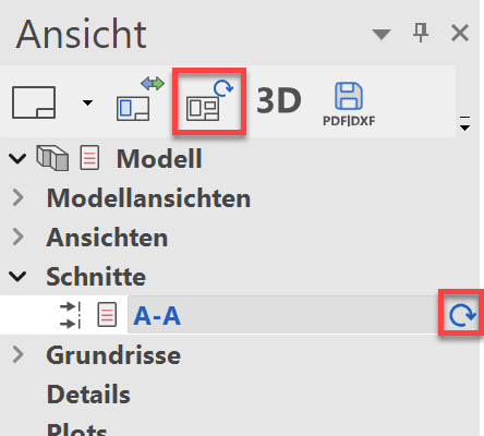
The missing floor finishes are now added to the section.

Edit view
The view is a calculated plan and behaves in the same way as a section.
Workshop
Larger areas can be concealed by a covering hatch.
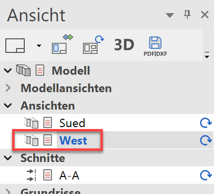
- Load the west view onto the screen.
- Select the function COVERING HATCH.

- Set the first point to the bottom left outside the building. For the second point, a temporary reference point must initially be set. Move with the cursor to the right onto the temporary help line and enter the direct value 50 in the value field.


To complete the hatch, click again on the end point.


- Cancel the function.
- Adding lines.
Prepare the location of the terrain lines again with a secondary drawing with auxiliary lines.
Caution: The lines below the covering hatch will be taken into account by the auto capture mode.

- Switch to the "Surroundings" layer.
- Select the DRAW function and create the terrain lines.

- Use the DELETE element function to delete the view lines of the slab face.
- Delete the auxiliary lines.

- Now process the south view in the same way.

Tip
If the wrong parts were deleted or incorrectly drawn, etc. this can be corrected with the functions UNDO and REDO.
![]()
![]()