Create views
View position
This function is used to observe the 3D object from any point and in any direction. You can finely tune the direction of view using the camera screen below. The design model depiction is automatically set to be in perspective.
Workshop
- Activate "Without structure".
Important: In the ARS version of ELITECAD, you cannot perform any action in the Storeys manager because the model has more than one structure. It does not matter that another storey may be currently active. You can specify the height of the camera in the camera window as you prefer. - Image start position and ZOOM ON FORMAT (or ++ctrl+pos1++)

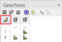
- Select the function VIEW POSITION.

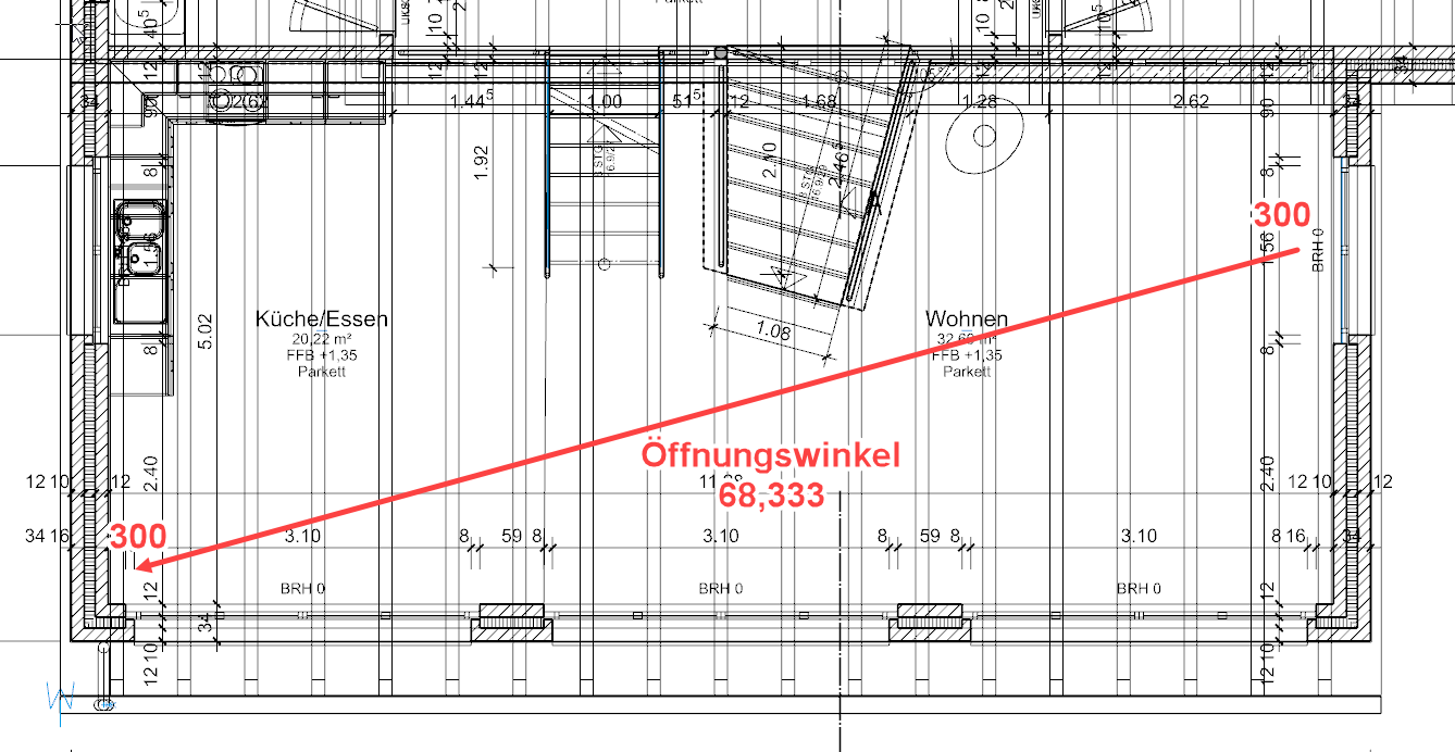
Please click standpoint or ++enter++ - Using the capture mode Freehand select the point P1.
Please enter height of standpoint - Enter the value 300 into the input line and confirm the value Enter.
Please click point of view point - Using the capture mode Freehand select the point P2.
Please enter height for view point - Enter the value 300 into the input line and confirm the value Enter.

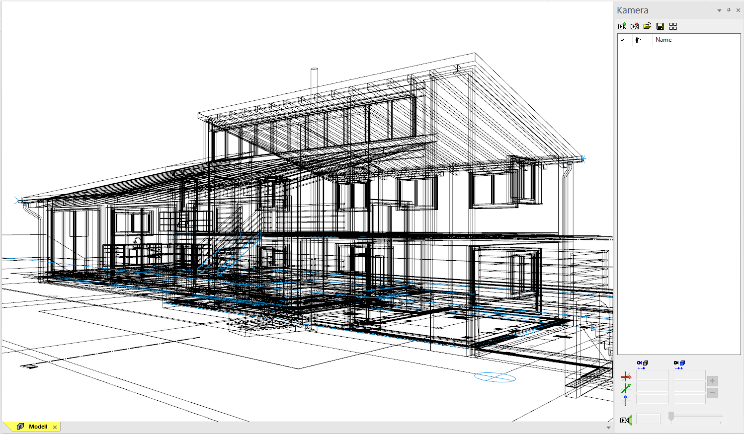
Camera
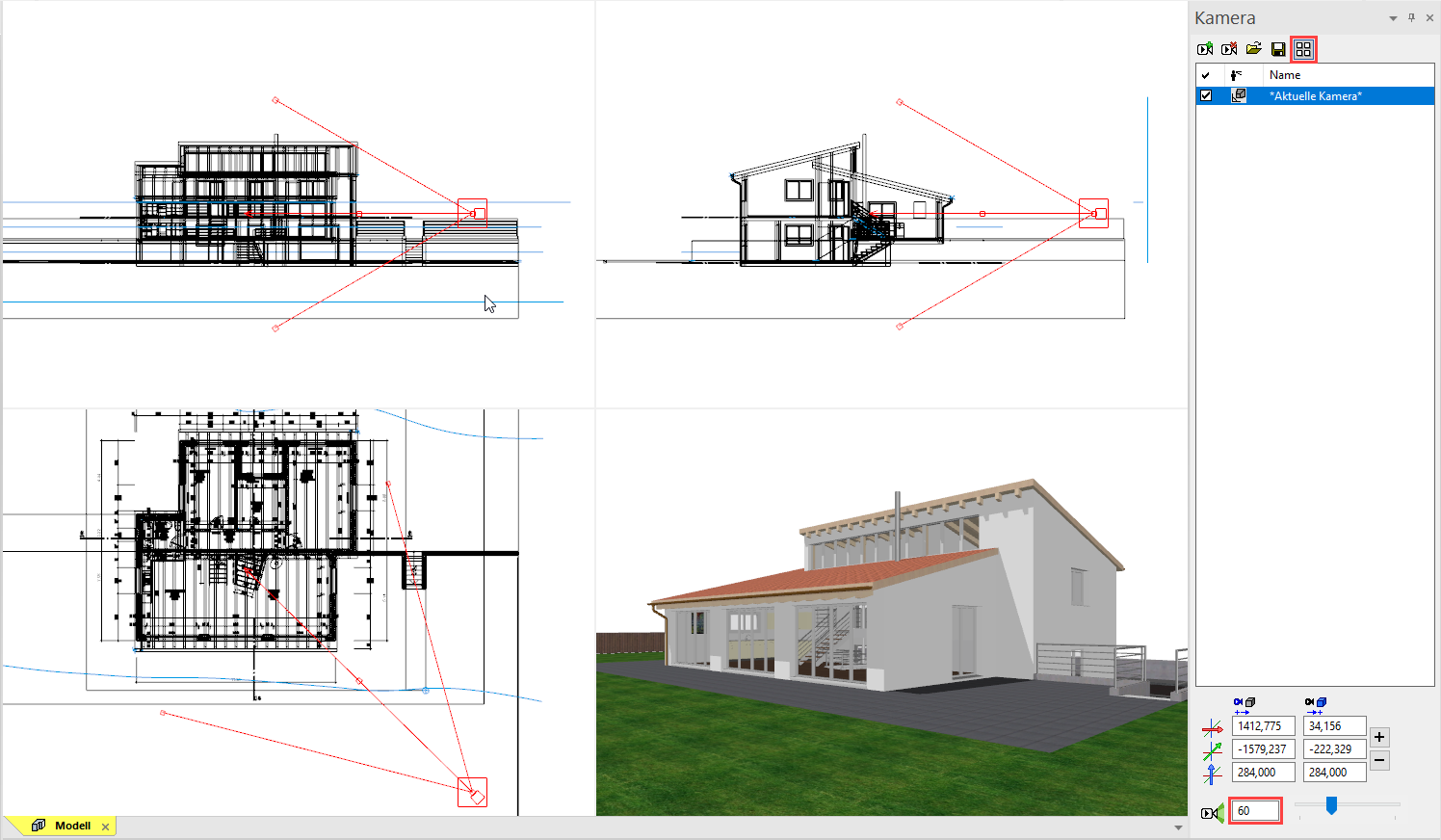
Modifications will be done in the 4-views window of the camera. If the camera screen is open, only the camera symbol can be clicked in CAD. Selecting or manipulating CAD objects is not possible. The depiction of the design model view can be controlled separately. If you right-click in this area, a menu opens where you can select how the design model view should be depicted. This is also true for the other views, as they are interconnected.
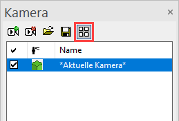
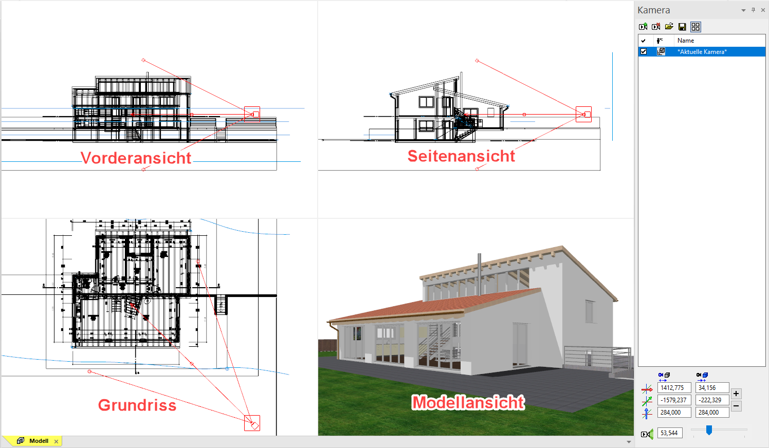
Using the camera in the 4-views window
Various handles are available, which you can use to manipulate the camera interactively while left-clicking.
| Modify position of camera | Move camera |
|---|---|
 |
 |
| Modify direction of camera | Modify opening angle of camera |
 |
 |
Workshop
- Set the opening angle in the camera screen to 60. This modification can be done with the slider or input direct a value in the field.

- Correct the angle of view so that the model is located roughly in the middle of the model window.
- Leave the camera adjustment by closing the 4-views mode and confirming the query with
 .
.

- Close now the camera window.
Create design model view
This function stores the 3D view angle currently set on your model as model view.
In case you wish to change the view angle of a view model, right-click in the view and select "Modify cut-out" from the context menu. You are now "within" the limitation framework and can move around using the centre mouse button and the zoom functions, as usual. The size of the section can also be changed using the handles. The camera position and the section are saved by pressing Esc or  .
.
Workshop
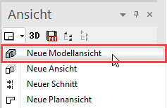
- Create new a design model view.
- Enter the name, set the depiction to solid, switch the background on and switch to Visualisation material mode.
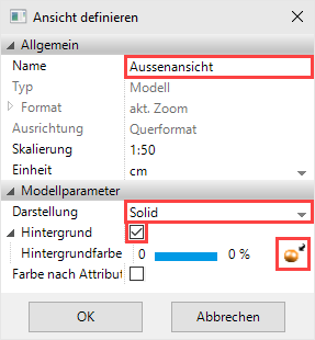
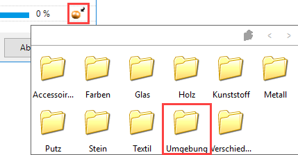
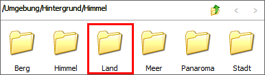
- In the Visualisation material mode, click on the selection button and then on Surroundings.
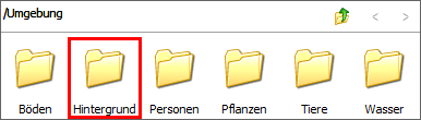
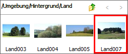
- Now switch to the folders 360 Panorama Environment/Photos/ and select the visualisation material Evening Meadow.
- Next, confirm the screen with
 .
.
- Load the design model view onto the screen.

- Save work copy Ctrl+W
Move background image
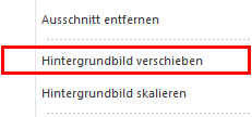
Depending on the camera setting and angle, moving or scaling the background image is required so that it fits correctly. To do so, right-click to open the context menu. Here you will see two menu items for Moving and Scaling. If you also press Ctrl when scaling, the image can be modified not to scale.
Workshop
- Right-click in the model window and select Move Panorama Environment.
Please indicate reference point - Now left-click in the image.
Please enter NEW position for alignment point - Set down the background image roughly as shown below.

- The function remains active so that the action can be repeated until the image is correct. Afterwards, cancel the function with Esc.
Create interior view
Now try to define another model view for the interior.
Workshop
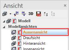
- Return to the model view and define another viewpoint in the living area.
- Save this camera as new model view as well. Enter the name Interior view and use the same options as described above. Load the view onto the screen and move the background image, too.
- Allocate visualisation materials to the interior view.
- Slab: Wood/Parquet/Parquet Walnut 02
- Stairs: Wood/Parquet/Parquet Walnut 02
- Truss: Wood/Timber/Oak 07
- Roofing: ~Archive/Wood/Cladding/Sheeting022
- Stove: Metal/Alu brushed 01
- Banister: Metal/Chrome smooth 01
- Kitchen worktop: Stone/Marble/Marble 12
- Slab faces for stair exit: Plaster/Plaster white 02
The interior view should now look roughly as follows:
