Box
Define box
|
|
3D toolbar, Free forms toolbar (AR), 3D-Object toolbar (ME) |
| Draw menu > 3D > Box |
This function is used to define a box from 2D lines.
Click on the CREATE BOX function to enable the settings for the last box drawn. The contour can now be drawn.
Tip
If the 2D contour is open at one point, the box is not created. The contour must first be correctly closed for a box to be generated.
Box property bar

The property bar becomes visible as soon as the DEFINE BOX function is started or if an existing box is edited.
| Function | Description |
|---|---|
| 3D object parameters | |
| Renovation planning state (only in Architecture) | |
| Colour selection (colour mode) | |
 |
Transparency in percentage (colour mode) |
| Material selection (material mode) | |
| Entry mode | |
| Entry mode for the base height | |
| Entry mode for the upper height | |
| Modify contour | |
| Resolution |
General properties see chapter General 3D parameters.
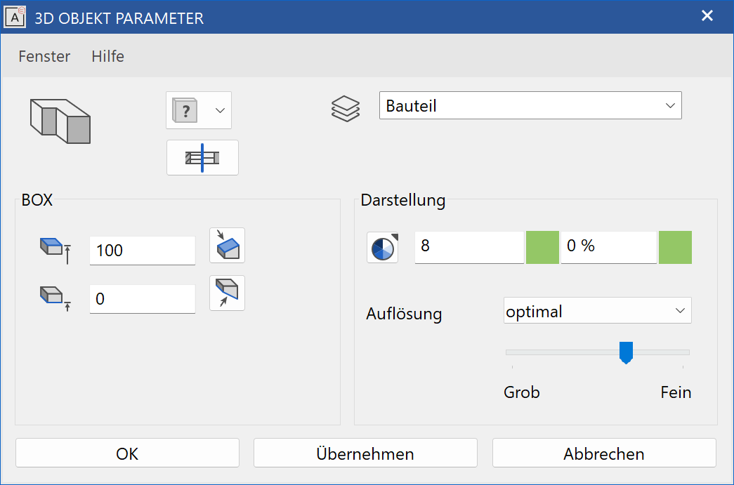
3D object parameters
![]()
Workshop
Define box
Draw a rectangle then click on DEFINE BOX and set the Entry mode * to Select contour. Set the base height to 0, the upper height to 100, the colour to 2* and click on the contour.
 |
 |
Several 3D definitions can even be created for the same contour. Now set the base height to 200, the upper height to 300, the colour to 3 and click on the rectangle again.
 |
Tip
The individual parameters of the boxes can be modified with the element part selection mode.
To create a slanted box, set the Entry mode * to 3 points. After you have drawn the rectangle, click on point 1 and enter a height of 0. Then click on points 2 and 3 and enter the heights 0 and -100. Proceed in exactly the same way for the upper height and enter the heights 100 and 200*. Slanted levels are then produced.
 |
 |
Rotation box
Define rotation box
|
|
3D toolbar, Free forms toolbar (AR), 3D-Object toolbar (ME) |
| Draw menu > 3D > Rotation box |
This function is used to define a rotation box from 2D lines.
Click on the CREATE ROTATION BOX function to enable the settings for the last rotation box drawn. The contour can now be drawn.
Tip
If the 2D contour is open at one point, the box is not created. The contour must first be correctly closed for the box to be generated.
Define rotation box

The property bar becomes visible as soon as the DEFINE ROTATION BOX function is started or if an existing rotation box is edited.
| Function | Description |
|---|---|
| 3D object parameters | |
| Renovation planning state (only in Architecture) | |
| Colour selection (colour mode) | |
|
Transparency in percentage (colour mode) |
| Material selection (material mode) | |
| Entry mode | |
| Start angle | |
| End angle | |
| Modify contour | |
| Modify rotation axis | |
| Resolution |
General properties see chapter General 3D parameters.
3D object parameters
![]()


Entry
Start angle, end angle

At this point, the start and end angles of the rotation box are displayed.
Centre line
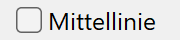
This option is only available in ELITECAD Mechanics. If the option is active, a centre line is created along the rotation axis, which adjusts to the size of the 3D object. The depiction settings are defined in the menu SETTINGS > OPTIONS > WORKING PARAMETERS > MECHANICAL LINES.
Modify rotation axis
![]()
This function redefines the axis for the rotation box.
Workshop
Define rotation box
Draw a contour, then click on DEFINE ROTATION BOX and set the start angle to 0, the end angle to -180 and the colour to 2. For the position of the axis, click on points P1 and P2 and click on the contour.
 |
|
|---|---|
 |
 |
Several 3D definitions can even be created for the same contour.
Then simply click again on DEFINE ROTATION BOX and set the start angle to 80, the end angle to 100 and the colour to 3.
Click once more on points P1 and P2 and click on the contour.
|
|---|
 |
Tip
The individual parameters of the rotation boxes can be modified with the element part selection mode.
Trans box
Define trans box
|
|
Free forms / curve toolbar (AR), Free forms toolbar (ME) |
| Draw menu > Free form > Trans box |
This function allows you to generate an object using a closed, planar contour (optional with cut-outs), that is moved along a path.
The procedure for defining an object is identical to that for defining a TRANS SURFACE, as the lateral surface of the trans box is a trans surface. Floor and slab surfaces are generated from the closed contour.
Tip
If polygons are nested and were drawn or clicked from outside inwards, cut-outs are produced.
Tip
If the 2D contour is open at one point, the trans box is not created. The contour must first be correctly closed for the object to be generated.
Tip
The contour and path do not have to be connected.
Trans box property bar

The property bar becomes visible as soon as the DEFINE TRANS BOX function is started or if an existing trans box is edited.
| Function | Description |
|---|---|
| 3D object parameters | |
| Renovation planning state (only in Architecture) | |
| Colour selection (colour mode) | |
|
Transparency in percentage (colour mode) |
| Material selection (material mode) | |
| Rotation type | |
| Modify contour | |
| Resolution |
General properties see chapter General 3D parameters.
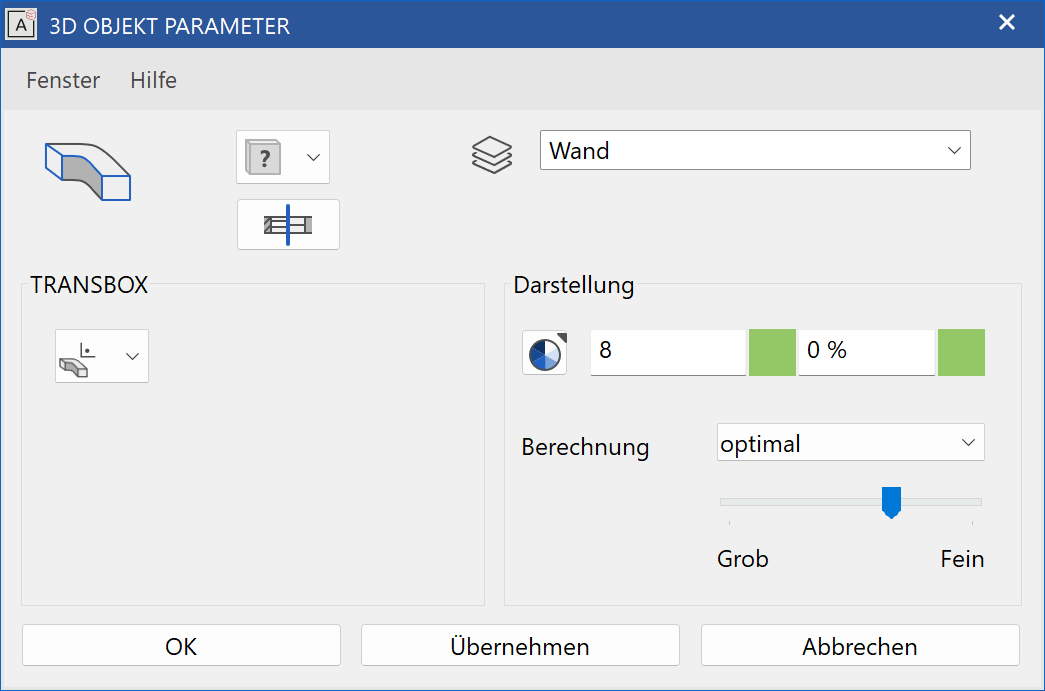
3D object parameters
Workshop
Define trans box
Draw a line with a connecting arc over centre point.
The work plane on which the contour is drawn must be perpendicular to the current work plane. To do this, use the CREATE WORK PLANE USING NORMAL function. After starting the function, click on points P1 and P2. Use Ctrl + Space to get to the starting position of the new work plane.
Now draw a rectangle. You can also start the first point of the rectangle with 0 Enter . This means that the current cursor position (P1) is the start point. The second point can be freely set. Reapply the work plane.
 |
 |
Now click on the DEFINE TRANS BOX function. The contour K must be clicked first, then the path W.
 |
 |
Design box
Define design box
|
|
Free forms / curve toolbar (AR), Free forms toolbar (ME) |
| Draw menu > Free form > Design box |
This function allows you to generate an object using a closed, planar contour that is converted to a second closed, planar contour along a path.
The procedure for defining an object is identical to that for defining a DESIGN SURFACE, as the lateral surface of the design box is a design surface. Floor and slab surfaces are generated from the contours.
Tip
If the 2D contour is open at one point, the design box is not created. The contour must first be correctly closed for the object to be generated.
Tip
The contour and path do not have to be connected.
Define design box

The property bar becomes visible as soon as the DEFINE DESIGN BOX function is started or if an existing design box is edited.
| Function | Description |
|---|---|
| 3D object parameters | |
| Renovation planning state (only in Architecture) | |
| Colour selection (colour mode) | |
|
Transparency in percentage (colour mode) |
| Material selection (material mode) | |
| Modify contour | |
| Resolution |
General properties see chapter General 3D parameters.
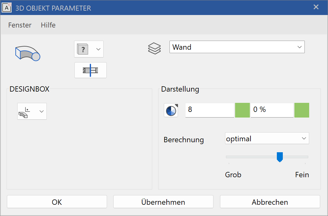
3D object parameters
Workshop
Define designbox
Draw a line for the path on the floor plan.
The work plane on which the contours are drawn must be perpendicular to the current work plane. To do this, use the CREATE WORK PLANE USING NORMAL function. After starting the function, click on points P1 and P2. Use Ctrl + Space to get to the starting position of the new work plane.
Now draw a rectangle. You can also start the first point of the rectangle with 0 Enter . This means that the current cursor position (P1) is the start point. The second point can be freely set. Reapply the work plane.
 |
 |
Now you need a second contour, which is copied and scaled in this example. Select the first contour and click on COPY SELECTION. Following the query Move which point? click on point P1. In the property bar that now appears, you can also scale in addition to copying. Press on the additional function "Scale", enter the value 0.2 and confirm the entry with Enter . Apply the smaller contour to point P2.
 |
Now click on the DEFINE DESIGN BOX function. The contour K1 must be clicked first, then the path W and finally the second contour K2.
 |
 |