Extrude
Define extrude
|
|
3D toolbar, Free forms toolbar (AR), 3D-Object toolbar (ME) |
| Draw menu > 3D > Extrude |
This function is used to define an extrude from 2D lines.
Click on the CREATE EXTRUDE function to enable the settings for the last extrude drawn. The contour can now be drawn.
Extrude property bar

The property bar becomes visible as soon as the DEFINE EXTRUDE function is started or if an existing extrude is edited.
| Function | Description |
|---|---|
| 3D object parameters | |
| Renovation planning state (only in Architecture) | |
| Colour selection (colour mode) | |
 |
Transparency in percentage (colour mode) |
| Material selection (material mode) | |
| Entry mode | |
| Entry mode for the base height | |
| Entry mode for the upper height | |
| Modify contour | |
| Resolution |
General properties see chapter General 3D parameters.
3D object parameters
![]()
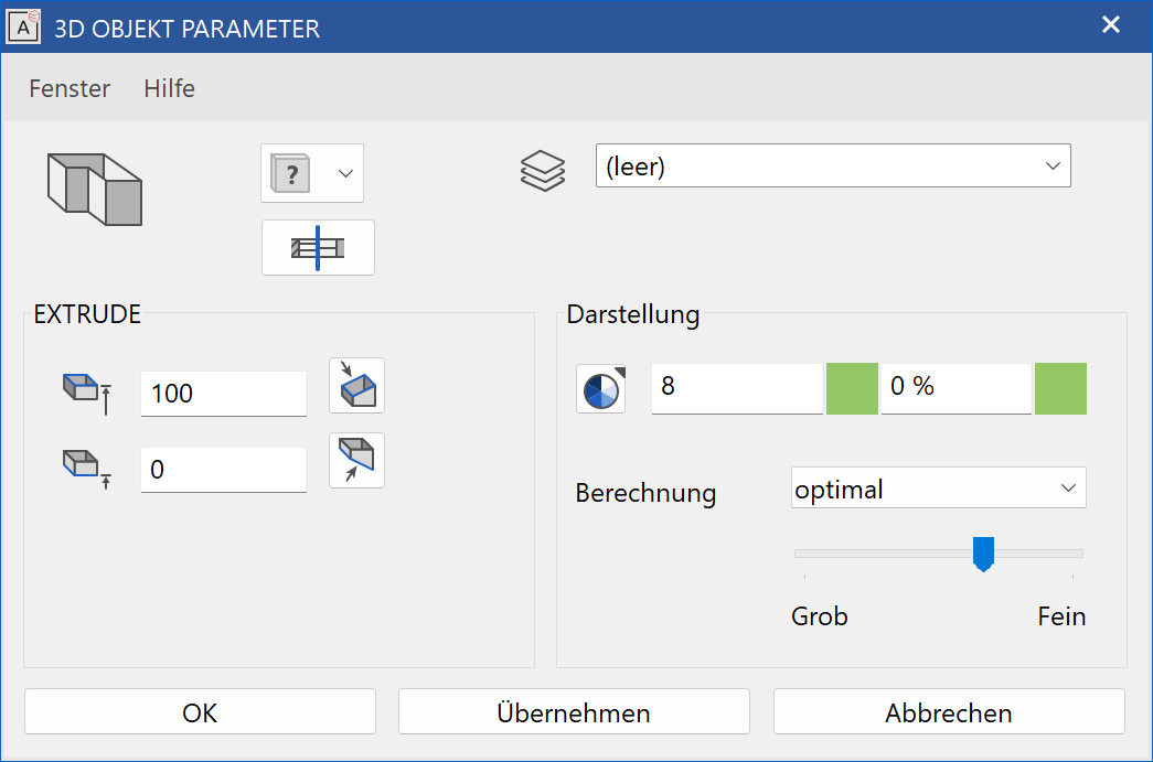
Workshop
Define extrude
Draw a contour then click on DEFINE EXTRUDE and set the Entry mode to Select contour. Set the base height to 0, the upper height to 100, the colour to 2 and click on the contour.
 |
 |
Several 3D definitions can even be created for the same contour.
Now set the base height to 200, the upper height to 300, the colour to 3 and click on the contour again.
 |
Tip
The individual parameters of the extrudes can be modified with the element part selection mode.
To create a slanted extrude, set the Entry mode * to 3 points. After you have drawn the contour, click on point 1 and enter a height of 0. Then click on points 2 and 3 and enter the heights 0 and -100. Proceed in exactly the same way for the upper height and enter the heights 100 and 200*. Slanted levels are then produced.
 |
 |
Rotation extrude
Define rotation extrude
|
|
3D toolbar, 3D-Object toolbar (ME) |
| Draw menu > 3D > Rotation extrude |
This function is used to define a rotation extrude from 2D lines.
Click on the CREATE ROTATION EXTRUDE function to enable the settings for the last rotation extrude drawn. The contour can now be drawn.
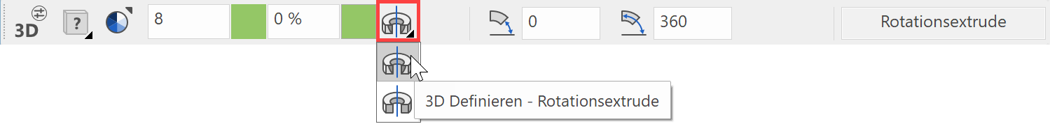
Explanation
Use the toolbar to start the ROTATION BOX function and switch to rotation extrude in the property bar.
Tip
The axis may not intersect the contour, otherwise an error occurs and the contour is displayed with the pen 0.
Rotation extrude property bar

The property bar becomes visible as soon as the DEFINE ROTATION EXTRUDE function is started or if an existing rotation extrude is edited.
| Function | Description |
|---|---|
| 3D object parameters | |
| Renovation planning state (only in Architecture) | |
| Colour selection (colour mode) | |
|
Transparency in percentage (colour mode) |
| Material selection (material mode) | |
| Entry mode | |
| Start angle | |
| End angle | |
| Modify contour | |
| Modify rotation axis | |
| Resolution |
General properties see chapter General 3D parameters.
3D object parameters
![]()


Entry
Start angle, end angle

At this point, the start and end angles of the rotation extrude are displayed.
Centre line
This option is only available in ELITECAD Mechanics. If the option is active, a centre line is created along the rotation axis, which adjusts to the size of the 3D object. The depiction settings are defined in the menu SETTINGS > OPTIONS > WORKING PARAMETERS > MECHANICAL LINES.
Modify rotation axis
![]()
This function redefines the axis for the rotation extrude.
Workshop
Define rotation extrude
Draw a contour, then click on DEFINE ROTATION EXTRUDE and set the start angle to 0, the end angle to -180 and the colour to 2. For the position of the axis, click on points P1 and P2 and click on the contour.
 |
|
|---|---|
 |
 |
Several 3D definitions can even be created for the same contour.
Then simply click again on DEFINE ROTATION EXTRUDE and set the start angle to 80, the end angle to 100 and the colour to 3.
Click once more on points P1 and P2 and click on the contour.
 |
|---|
 |
Tip
The individual parameters of the rotation extrude can be modified with the element part selection mode.