Objects
2-views object
Define 2-views object
|
|
3D toolbar, Free forms toolbar (AR), 3D-Object toolbar (ME) |
| Draw menu > 3D > 2-views object |
This function is used to generate a 3D object from its projections in two non-parallel planes.
Before accessing the function, a planar, closed contour must be created for each of the first and second view.
After activating this function, the two views must be selected by clicking and confirming with Enter . After you click on the two contours, the 3D geometry is created.
Tip
If polygons are nested and were clicked from outside inwards, cut-outs are produced.
2-views object property bar

The property bar becomes visible as soon as the DEFINE 2-VIEWS OBJECT function is started or if an existing 2-views structure is edited.
| Function | Description |
|---|---|
| 3D object parameters | |
| Renovation planning state (only in Architecture) | |
| Colour selection (colour mode) | |
 |
Transparency in percentage (colour mode) |
| Material selection (material mode) | |
| Modify contour | |
| Resolution |
General properties see chapter General 3D parameters.
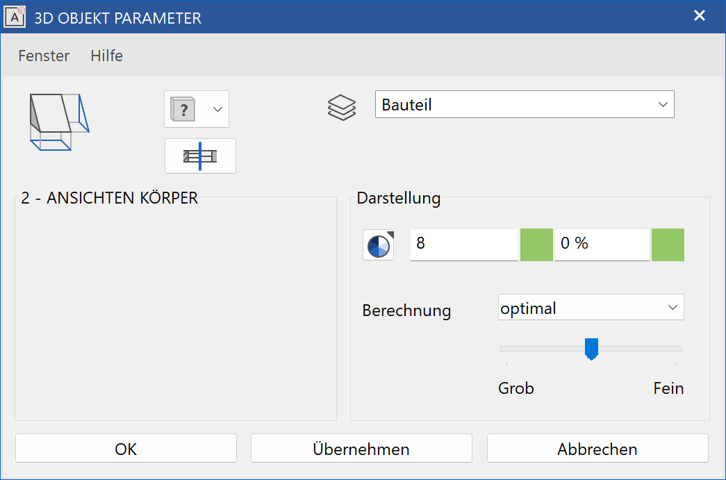
3D object parameters
![]()
Workshop
Define 2-view object
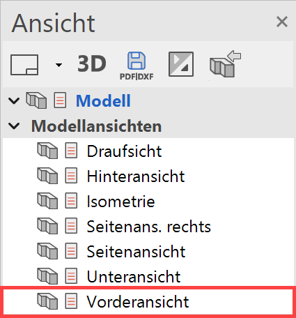
In this example, the first contour is drawn in the front view. In views management, switch to the front view.
Create 4 parallel help lines with the distance 100 cm to each of the points P1 and P2.
 |
|
|---|---|
 |
 |
Now draw a triangle. The help lines can then be deleted again. Then switch back to the model view.
 |
|
|---|---|
 |
 |
Now select the contour and go to the COPY SELECTION function. Following the query Move which point? click on point P1. In the property bar that now appears, you can also rotate 90 degrees to the left in addition to copying. Press the additional function ROTATE. Now the contour can be placed in its new position. Click on point P1 again.
 |
 |
Select the DEFINE 2-VIEW OBJECT function. Click on the contours K1 and K2 and confirm each with Enter .
 |
 |
3-views object
Define 3-views object
|
|
3D toolbar, Free forms toolbar (AR), 3D-Object toolbar (ME) |
| Draw menu > 3D > 3-views part |
This function is used to generate a 3D object from its projections in three non-parallel planes.
Before accessing the function, a planar, closed contour must be created for each of the three views.
After activating this function, the three views must be selected by clicking and confirming with Enter . After you click on the contours, the 3D geometry is created.
Tip
If polygons are nested and were clicked from outside inwards, cut-outs are produced.
3-views object property bar

The property bar becomes visible as soon as the DEFINE 3-VIEWS OBJECT function is started or if an existing 3-views object is edited.
| Function | Description |
|---|---|
| 3D object parameters | |
| Renovation planning state (only in Architecture) | |
| Colour selection (colour mode) | |
|
Transparency in percentage (colour mode) |
| Material selection (material mode) | |
| Modify contour | |
| Resolution |
General properties see chapter General 3D parameters.
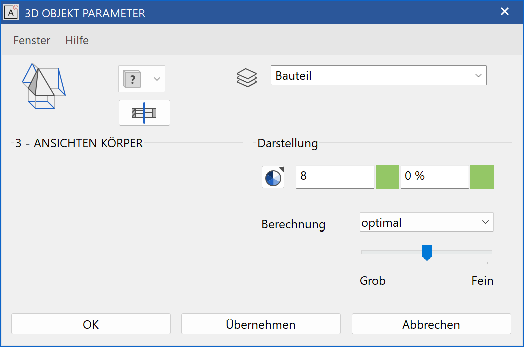
3D object parameters
![]()
Workshop
Define 3-views object
To draw the first two contours, proceed in exactly the same way as in the workshop for the 2-VIEWS OBJECT.
Use Ctrl + Space to return to the starting position and transfer 5 parallel help lines with the distance 80 cm to each of points P1 and P2.
 |
|
|---|---|
|
|
Now draw a polygon as illustrated below. The help lines can be deleted again afterwards.
 |
 |
Select the DEFINE 3-VIEWS OBJECT function. Click on the contours K1 to K3 and confirm each with Enter .
 |
 |
Standard 3D objects
|
|
Standard 3D objects toolbar |
| Draw menu > 3D > Standard 3D objects |
This function is used to create standard 3D objects easily. You can select from the symbols illustrated below.
After clicking on each function, the corresponding queries appear above the entry line.
 |
 |
 |
 |
 |
 |
 |
 |
 |
 |