Planar Surface
Define planar surface
|
|
3D toolbar, Free forms toolbar (AR), 3D-Object toolbar (ME) |
| Draw menu > 3D > Surface |
This function is used to define a surface from a closed 2D contour.
Click on the CREATE PLANAR SURFACE function to enable the settings for the last planar surface drawn. The contour can now be drawn.
Tip
If the 2D contour is open at one point, the surface is not created. The contour must first be correctly closed for the surface to be generated.
Planar surface property bar

The property bar becomes visible as soon as the DEFINE SURFACE function is started or if an existing surface is edited.
| Function | Description |
|---|---|
| 3D object parameters | |
| Renovation planning state (only in Architecture) | |
| Colour selection (colour mode) | |
 |
Transparency in percentage (colour mode) |
| Material selection (material mode) | |
| Entry mode | |
| Entry mode for the base height | |
| Modify contour | |
| Resolution |
General properties see chapter General 3D parameters.
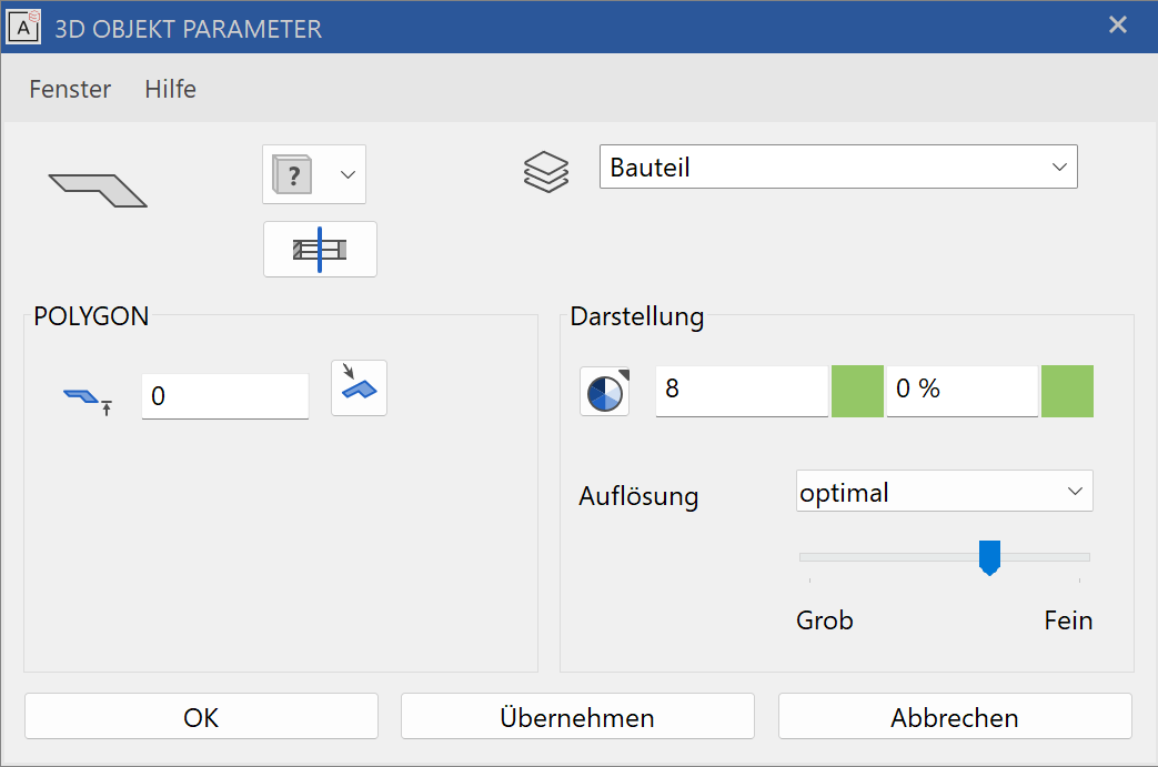
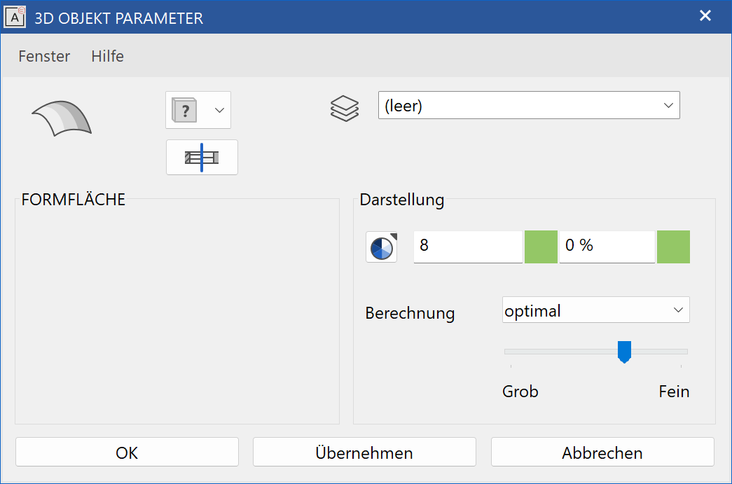
3D object parameters
![]()
Workshop
Define surface
Draw a rectangle, then click on DEFINE SURFACE and set the Entry mode to Select contour. Set the height to 0, the colour to 2 and click on the rectangle.
 |
 |
Several 3D definitions can even be created for the same contour. Now set the height to 50, the colour to 3 and click on the rectangle again.
 |
Tip
The individual parameters of the surfaces can be modified with the element part selection mode.
To create a slanted surface, set the Entry mode to 3 points. After you have drawn the contour, click on point 1 and enter a height of 0. Then click on points 2 and 3 and enter the heights 100 and 200. This creates a slanted level.
 |
 |
Trans surface
Define trans surface
|
|
Free forms / curve toolbar (AR), Free forms toolbar (ME) |
| Draw menu > Free form > Trans surface |
This function allows you to generate a surface using one or more contours that are moved along a path.
After activating this function, click on the contour and confirm with [Enter]. The selected contour is displayed in magenta. Then click on the path and the trans surface is created.
The following options are available for selection as a contour or path:
- 2D contour
- 2-views curve
- Extracted border curve
Explanation
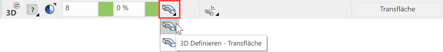
Use the toolbar to start the TRANS BOX function and switch to trans surface in the property bar.
Tip
The contour and path do not have to be connected.
Trans surface property bar

The property bar becomes visible as soon as the DEFINE TRANS SURFACE function is started or if an existing trans surface is edited.
| Function | Description |
|---|---|
| 3D object parameters | |
| Renovation planning state (only in Architecture) | |
| Colour selection (colour mode) | |
|
Transparency in percentage (colour mode) |
| Material selection (material mode) | |
| Rotation type | |
| Modify contour | |
| Resolution |
General properties see chapter General 3D parameters.
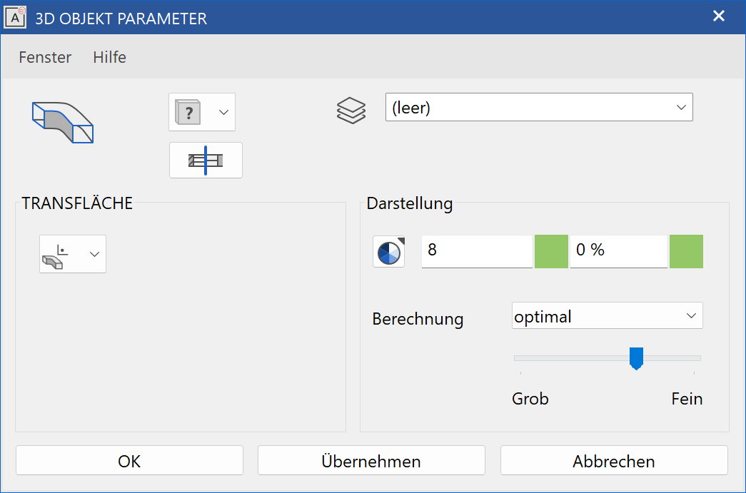
3D object parameters
Workshop
Define trans surface
Draw a line with a connecting arc over the centre point.
The work plane on which the contour is drawn must be perpendicular to the current work plane. To do this, use the CREATE WORK PLANE USING NORMAL function. After starting the function, click on points P1 and P2. Use Ctrl + Space to get to the starting position of the new work plane.
Draw a line again with a connecting arc. You can also start the first point of the line with 0 Enter . This means that the current cursor position (P1) is the start point. After drawing, reset the work plane.
 |
 |
Now click on the DEFINE TRANS SURFACE function. The contour K must be clicked first, then the path W.
 |
 |
Design surface
Define design surface
|
|
Free forms / curve toolbar (AR), Free forms toolbar (ME) |
| Draw menu > Free form > Design surface |
This function allows you to generate a surface using a contour that is transformed into a second contour along a path.
After activating this function, click on the first contour. The selected contour is displayed in magenta. Then click on the path. The selected path is displayed in magenta. After you click on the second contour, the design surface is created.
The following options are available for selection as a contour or path:
- 2D contour
- 2-views curve
- Extract border curve
Explanation
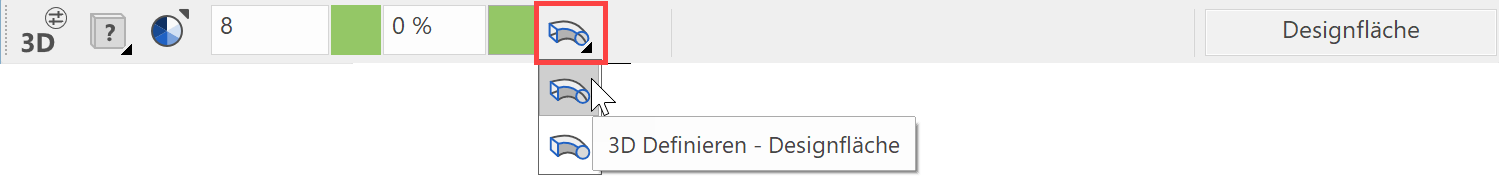
Use the toolbar to start the DESIGN BOX function and switch to design surface in the property bar.
Tip
The contour and path do not have to be connected.
Design surface property bar

The property bar becomes visible as soon as the DEFINE DESIGN SURFACE function is started or if an existing design surface is edited.
| Function | Description |
|---|---|
| 3D object parameters | |
| Renovation planning state (only in Architecture) | |
| Colour selection (colour mode) | |
|
Transparency in percentage (colour mode) |
| Material selection (material mode) | |
| Modify contour | |
| Resolution |
General properties see chapter General 3D parameters.
3D object parameters

Workshop
Define design surface
Draw a line for the path on the floor plan.
The work plane on which the contours are drawn must be perpendicular to the current work plane. To do this, use the CREATE WORK PLANE USING NORMAL function. After starting the function, click on points P1 and P2. Use Ctrl + Space to get to the starting position of the new work plane.
Draw a connecting line. You can also start the first point of the line with 0 Enter . This means that the current cursor position (P1) is the start point. After drawing, reapply the work plane.
 |
 |
Now you need a second contour, which is copied and scaled in this example. Select the first contour and click on COPY SELECTION.
Following the query Move which point? click on point P1. In the property bar that now appears, you can also scale in addition to copying. Click on the SCALE button, enter the value 0.2 and confirm the entry with Enter . Apply the smaller contour to point P2.
 |
Now click on the DEFINE DESIGN SURFACE function. The contour K1 must be clicked first, then the path W and finally the second contour K2.
 |
 |
Free form surface
Define Free form surface
|
|
Free forms / curve toolbar (AR), Free forms toolbar (ME) |
| Draw menu > Free form > Free form surface |
This function allows you to generate a surface using four limit lines (2 contours and 2 paths).
After activating this function, click on contour 1. The selected contour is displayed in magenta. Then click on path 1. Once you have clicked on contour 2 and path 2 the free form surface is created.
The following options are available for selection as a contour or path:
- 2D contour
- 2-views curve
- Extract border curve
Tip
Contours and paths must be connected to the start and end points.
Free form surface property bar

The property bar becomes visible as soon as the DEFINE FREE FORM SURFACE function is started or if an existing free form surface is edited.
| Function | Description |
|---|---|
| 3D object parameters | |
| Renovation planning state (only in Architecture) | |
| Colour selection (colour mode) | |
|
Transparency in percentage (colour mode) |
| Material selection (material mode) | |
| Modify contour | |
| Resolution |
General properties see chapter General 3D parameters.
3D object parameters
Workshop
Define free form surface
In this example, the first contour is drawn in the front view. In views management, switch to the front view.
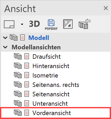
Now draw a CURVE BY 3 POINTS.
You can start the first point of the curve P1 with 0 Enter . This means that the current cursor position (P1) is the start point. The second point P2 and the third point P3 can be freely set. Then switch back to the model view.
 |
|---|
 |
Now select the contour and go to the COPY SELECTION function. Following the query.
Following the query Move which point? click on point P1. In the property bar that now appears, you can also rotate, mirror and copy multiple times in addition to copying. Press the additional functions ROTATE, MIRRORING 3D and MULTIPLE COPY one after the other. Now the query How often? appears in the entry line. Enter the number 3 and confirm with Enter . Now the contour can be placed in its new position. Click on point P3.
 |
 |
Select the DEFINE FREE FORM SURFACE function. Now click on contour K1, path W1, contour K2 and finally path W2 one after the other.
 |
 |