General 3D Parameters
Common parameters
In the property bar and in the main parameter dialog window for 3D objects, some parameters and functions are universal for all 3D objects and are described in this chapter for all types.
Layer/name


Either the layer or the name of the object is edited here.
The name is available if Selection using group/class/level is activated in the OPTIONS. This is the preferred setting in ELITECAD Mechanics.
Material

This setting is only available in ELITECAD Mechanics. The assigned material is added as an attribute to the object and listed in the bill of material. This information is used to calculate the weight of an object if the volume is available. Additionally, the hatch for sections is defined by the material. A necessary requirement for the calculation is for there to be a specific weight for the material defined in the database.
Colour, transparency/visualisation material

Here you can select the colour and transparency, as well as the material for 3D depiction.
It is not possible to select a transparency for 3D curves and there is no material mode available for 3D curves.
The exact description of the COLOUR SELECTION menu can be found in the chapter Colours.
Colour mode/Material mode
![]()
![]()
This switch allows you to toggle between colour mode and material mode. For more details, see the Colours and Materials chapters.
Colour selection – direct entry

The surface colour can be entered directly. (from 0-1023)
Colour selection over table

Here the colour is selected using a colour table.
Colour mode/Material mode
This function is only available in ELITECAD Architecture.
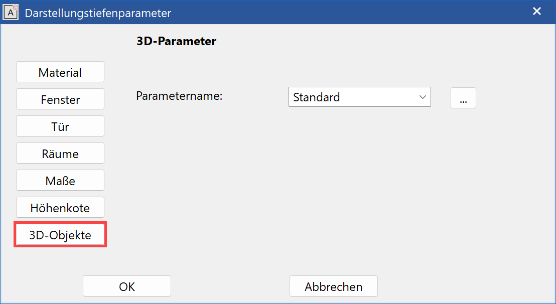
![]()
The depiction of 3D objects in views depending on the representation level can be changed here.
Renovation planning state
This function is only available in ELITECAD Architecture.
![]()
This function is used to set the renovation planning state. See chapter Renovation planning state.
Entry mode
You have two options available for generating 3D objects: Either draw the contour directly, or you can draw a closed polygon before accessing the function and "define" it as a 3D object.
For some 3D objects, it is required that the contour is a closed polygon.
Tip
If polygons are nested and were drawn or clicked from outside inwards, or are in the selected area, cut-outs are produced.
Entry over contour
![]()
The definition is done by directly drawing a polygon. Once you have reached the start point of the drawing again, the function defines the 3D object immediately.
If open contours are allowed, the polygon input is finished by entering the last point twice.
Entry over select contour
![]()
Click on the outline of the polygon to generate the 3D object.
Entry over selection
If a selection has already been made when this function is selected, a query appears as to whether this selection should be used.
Resolution
![]()
This function is used to set parameters for the resolution. You find a detailed description at the chapter MODIFY>RESOLUTION.
Modify contour
![]()
Using this function, you can change the contour of the surface at a later point.
Once you have clicked on the function, the 2D contour of the 3D object is automatically displayed.
For objects, which are defined by multiple contours, a selection window appears at the top left corner of the screen, where the desired contour can be chosen. The selection is confirmed by either the Enter button or by confirming in the dialog.
Now change the contour with the usual 2D drawing functions. Close the function with the "Contour finished" button at the top left corner of the graphics window.
Tip
After selecting the surface, click on a handle or gripper of the contour to access manipulation functions directly in a toolbar or by the cursor by using Tab .
3D object history
![]()
This button allows to open the function 3D OBJECT HISTORY for the currently selected 3D object. This function is not offered for 3D curves and point clouds.
Type specific parameters
In the property bar and in the main parameter dialog window for 3D objects, some parameters and functions are universal for multiple 3D objects and are described in this chapter together for corresponding types.
Planar Surface, extrude and box
| Planar Surface | Extrude | Box |
|---|---|---|
 |
 |
 |
The height is the distance of the planar surface from the work plane.
The base and upper heights for extrude and box are the limitation planes perpendicular to the work plane.
If the limitation plane is not perpendicular to the work plane, then instead of the height value the note "inclined" is displayed.
Height entry mode
Limitation plane over heights
![]()
![]()
![]()
![]()
![]()
The height can be entered as a numerical value (in the currently set unit) in the property bar.
Limitation plane over point entry
![]()
![]()
![]()
![]()
![]()
The height can be directly defined using the CAPTURE FUNCTIONS by selecting a height marker in the 3D model.
Limitation plane over 3 points
![]()
![]()
![]()
![]()
![]()
This defines the surface over three points. The height is queried for each point. The definition of three Z-coordinate points for the slanted surface can take place anywhere on the screen, and is not linked to the contour elements.
Tip
It is also possible to select points directly in the 3D model here. The clicked height is recommended above the entry line and can be easily confirmed with Enter .
Limitation plane over surface
![]()
![]()
![]()
![]()
![]()
Clicking on an existing surface defines the position.
Rotation extrude and rotation box

The start and end angles for rotation are entered here.
Rotation type
For Trans surface, Trans box, Design surface, Design box, Free form surface and 2-views curve
![]()
The most common rotation types can be selected in the property bar for the trans box and trans surface.
![]() Parallel (type 1)
Parallel (type 1)
![]() Symmetrical (type 5)
Symmetrical (type 5)
In ELITECAD Mechanics, there is a second creation method for the types 1-8 numbered 101-108.
![]() Standard (type 102)
Standard (type 102)
![]() Standard rounded (type 108)
Standard rounded (type 108)
The rotation type for the remaining 3D definitions is set in the respective main parameter dialogs. The free type offers the possibility to enter the number of the type manually.

Starting position for the examples is a trans surface with the following origin:


Type 1: ![]() parallel
parallel
The contour is moved along the path without changing its position in space.


Type 2:
The contour is moved perpendicular to the path. The edge of the surface is perpendicular to the path.


Type 3:
The contour is moved perpendicular to the path. The edge of the surface is at the same angle to the path at the start and the end. The angle corresponds to the angle between the contour and the path.


Typ 4:
The contour is moved perpendicular to the path. The edge of the surface maintains the angle between the contour and path on one side and ends perpendicular on the other side.


Type 5: ![]() symmetrical
symmetrical
The contour is moved perpendicular to the path. The edge of the surface maintains the angle between the contour and path on one side and ends symmetrical on the other side.


Type 6:
The contour is moved along the path and maintains the enclosed angle. Gaps that result from folds are filled.


Type 7:
The contour is moved along the path and maintains the enclosed angle. The angle changes if there are folds.


Type 8:
The contour is moved along the path and maintains the enclosed angle. Gaps that result from folds are filled with a round joint.


Type 101, 102 for design box and design surface:
Design surface and Design box
This special type is only available in ELITECAD Mechanics and is valid for the 3D types design box and design surface.
The type 102 uses the direction of the path contour at the start and end points as a tangent for the surface. With the type 101 the path contour is irrelevant for the generation. The surface with the shortest connection is created for the type 101.
| Type 102 | Type 101 |
|---|---|
 |
 |
Delta
The tolerance with which two border curves are considered to be connected. Default value is 0.01 mm. Only displayed for 3D objects defined in the Window Manager of ELITECAD 6.0.
Height
Only displayed for 3D objects defined in the Window Manager of ELITECAD 6.0.
Operator Definition
The following types of operations are possible:
Minus operation, join, section, and fillet
Online
The definition is only updated if online is switched on.
Radius
Only possible for fillet operations; radius for fillet surface.
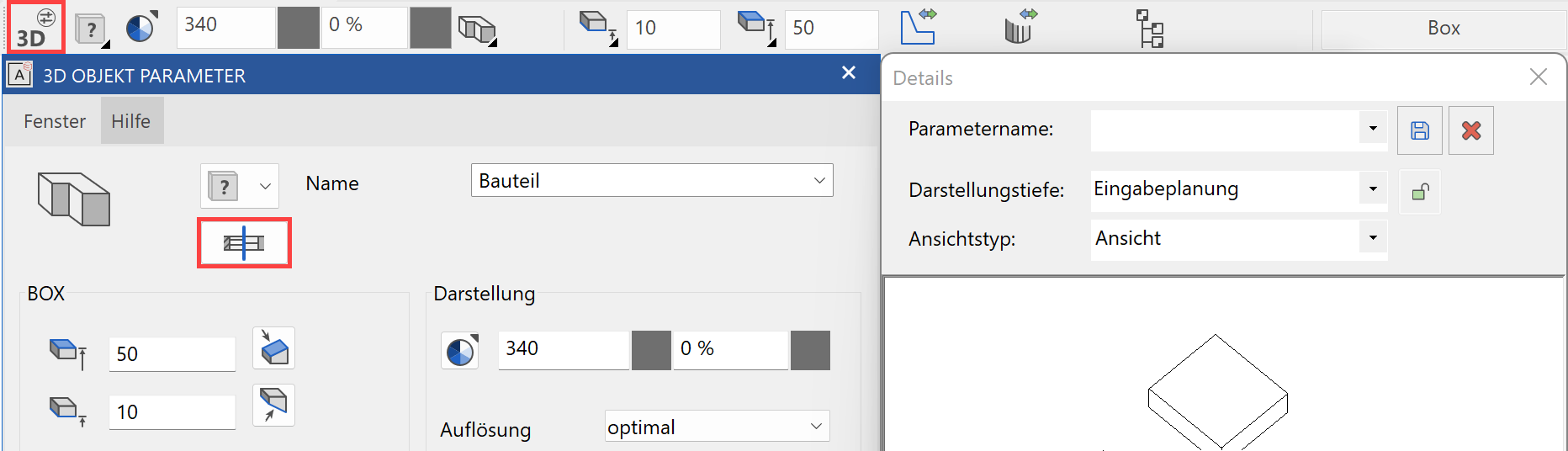
Depiction
This function is only available in ELITECAD Architecture.
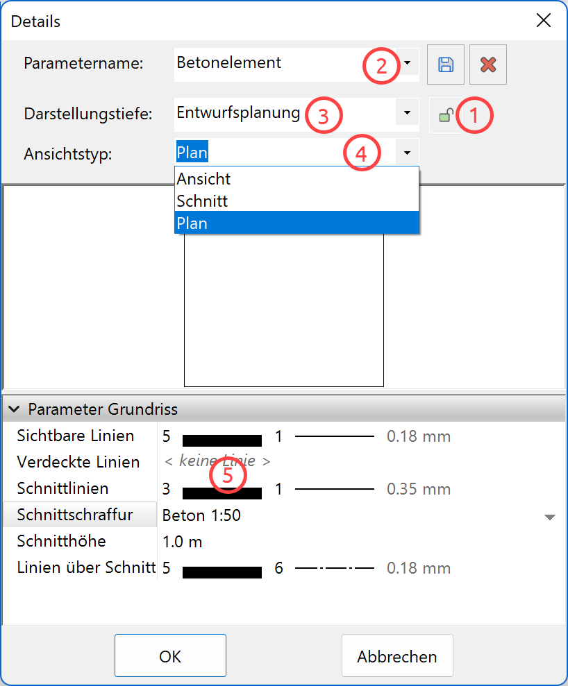
3D objects are subject to the representation level, therefore allowing a depiction that is true to the material for views, sections and floor plans each at the appropriate scale.
Each newly defined 3D definition is automatically assigned the default parameters from the representation level.
To obtain an individual depiction of single definitions, a created definition is assigned its own material.
Once the link (1) is detached from the representation level, an existing parameter can be selected (2) or a new parameter record can be directly created. The settings (5) must be made per representation level (3) and view type (4). The settings (5) differ for each view type.