3D specific functions
Modify resolution
|
|
3D toolbar |
| Settings menu > Resolution |
This function is used to configure the parameters for 3D resolution. You can choose between equal resolution and curve-dependent resolution. The analytical data model with NURBS is an exact description of curves and surfaces. For the graphic display, facets must be harmonised – however, the resolution can be as high as you wish. The higher the resolution, the better the graphics but the longer the rendering time.
There are multiple options for configuring the detail of depiction.
Configuring the parameters for each definition individually:
In the property bar for the relevant definition
toolbar * Modify > 3D-OBJECT PARAMETERS
MODIFY menu > 3D-OBJECT PARAMETERS
Configuring the parameters globally:
|
|
3D toolbar |
| Settings menu > Resolution |
This has the following advantages:
Using global resolution, high or low resolution can be quickly configured for the entire image. If individual parameters are changed, an individual object can be displayed in high resolution without requiring a lot of rendering time for the others.
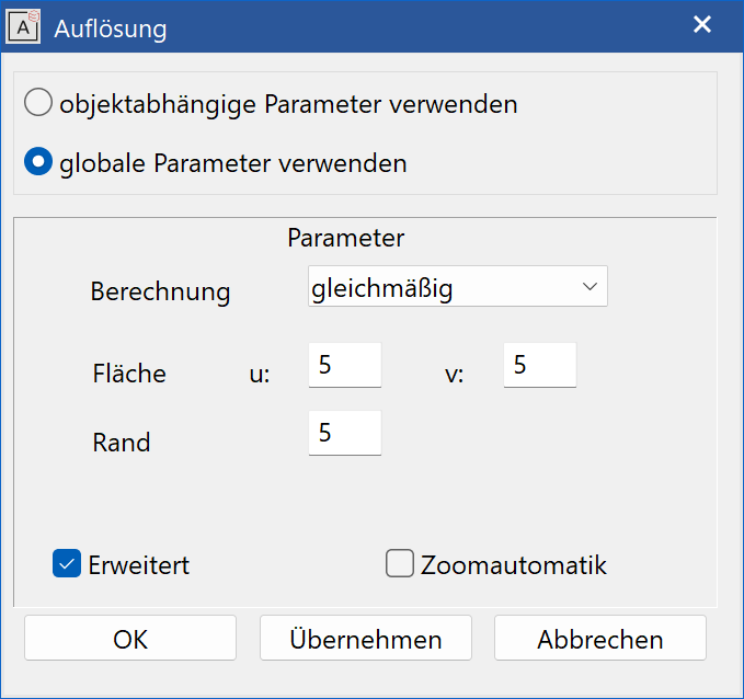
Parameters
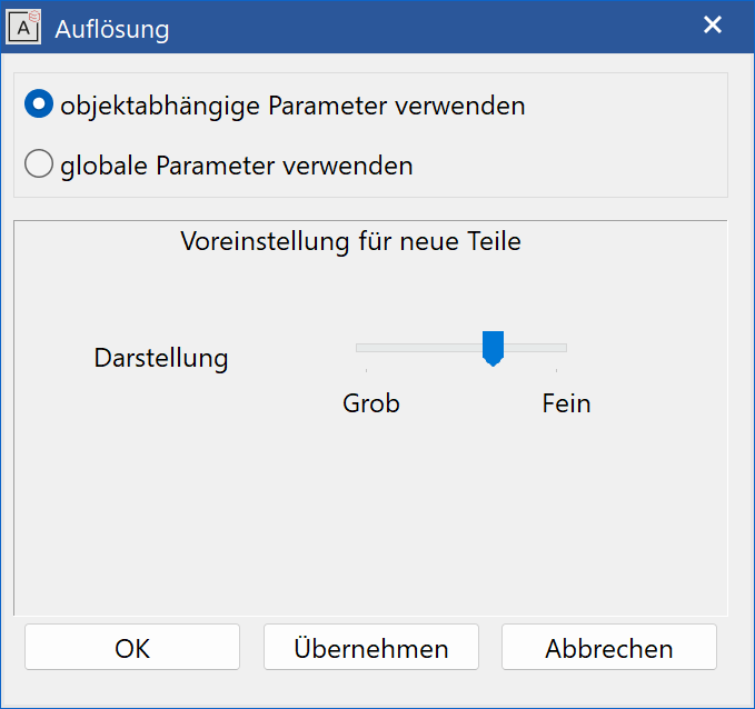
Use object dependent parameters
The depiction resolution configured here is used as a default setting for new 3D objects.
Use global parameters
If this option is activated, the configured values for depiction are used for all 3D definitions. If this option is not activated, the parameters entered for the definition are used for depiction.
Use the EXTENDED option to differentiate between different calculation modes. In addition, there is the AUTOMATIC ZOOM option. If this option is activated, complex 3D objects are only displayed exactly if they are zoomed in upon. This has an impact on performance speed.
Optimal
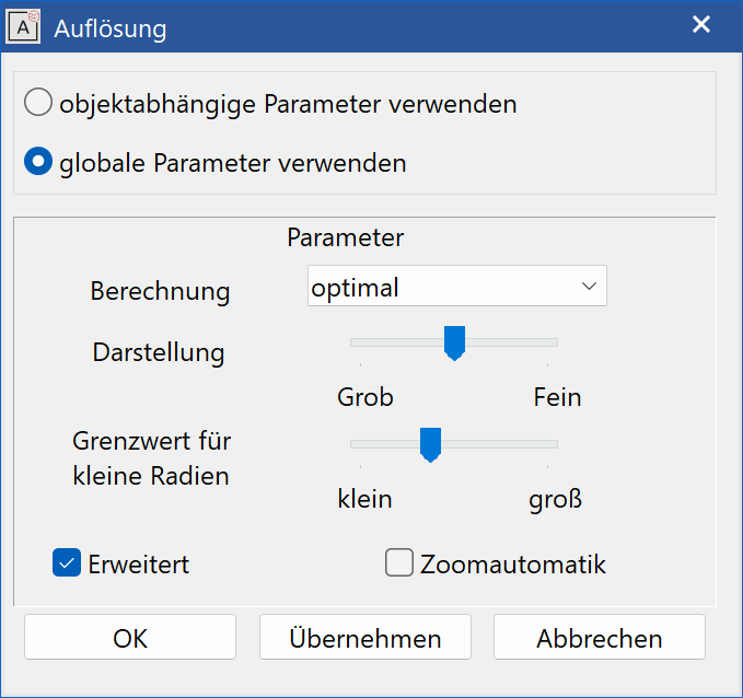
Depiction
Use the slider to move between low and high depiction.
Limit for small radials
Use the slider to move from a small to a large limit.
Curvature dependent resolution
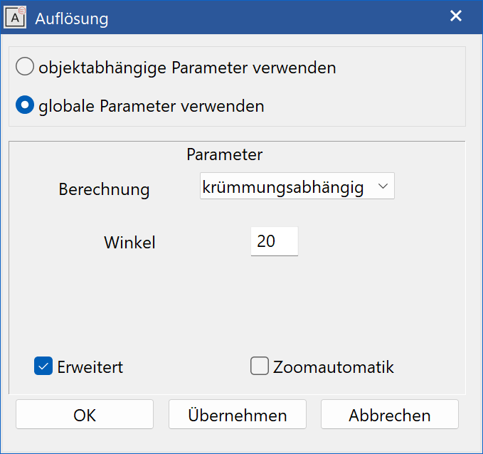
Curvature-dependent resolution means that the surfaces are only divided where a configurable curvature value is exceeded. Sufficiently flat facets are not divided any further. This results in the number of points being considerably smaller than with equal resolution, and dynamic movements are faster.
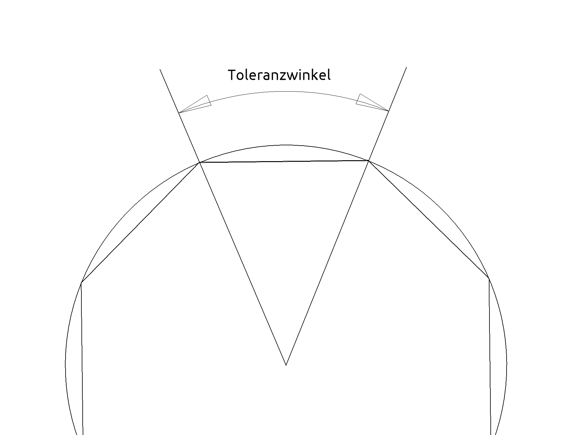
Angle
The tolerance angle indicates to what maximum degree the surface normal may differ to the left and right edge of a facet (or above – below). The tolerance angle can also be considered being the maximum change of one facet in regards to the adjoining facet. The smaller the tolerance angle, the higher the resolution.
Uniform resolution
Explanation
NURBS surfaces are made up of segments. A straight part or a quadrant is normally converted into one segment (e.g. the lateral surface of a cuboid or a cylinder comprises four segments).)
Surface
The surface resolution indicates how often a segment is to be divided. A rectangular surface can be divided in two directions at different resolutions. The directions are usually referred to as U and V. In general, the U resolution is the direction of the model and the V resolution is the extrude or rotation direction. With free form surfaces made up of two, three or four border curves, the U direction is generally the contour and the V direction the path.
Border
The border resolution indicates to what degree the border of a facet should be divided. This value is also used for segmenting trimming curves.
OK

This function applies the values and then removes the entry mask from the screen.
Apply

This function applies the configured values without removing the entry mask from the screen.
Cancel

This function removes the dialog window from the screen without adopting the values.
Tip
Optimisations:
For some surfaces, the resolution is optimised. It is of no use fragmenting a planar rectangular surface into several facets – quite the contrary, as this increases processing time and memory usage. For surfaces that are planar in at least one direction (polygon, extrude, box), the configured resolution is ignored. A cuboid does not need to be divided further in the direction of the extrude – surface resolution 1 would suffice. The resolution can also be kept lower for a cylinder. The lateral surface is fragmented into eight facets (curved) by default, with a high-resolution border. However, to give users the chance to implement their settings for optimal graphics, optimisation is switched off for surface resolutions > 10.
Verify 3D tree
|
|
Special functions toolbar |
| Menu Extras > Special functions > Verify 3D tree |
This function is only available in ELITECAD Mechanics.
Basics

A series of interdependent 3D operations can be represented as a tree. The 3D base definitions, such as boxes or extrudes or any special parts, are located at the lower positions. Each further processing step is one level higher in the tree. Boolean operations merge multiple branches into one. At the top is the current end result.
If a change is now made to an intermediate step, generally all dependent results also change. The program tries to recalculate all dependent 3D operations of a changed definition (unless the user sets an operation to "offline").
Because of these changes, various operations defined as intermediate steps generally change, or some operations are no longer possible. This is especially true for operations related to certain edges or faces of the model, such as edge fillets, chamfers or draft operations.
In order not to destroy the model or to create an incorrect model when re-calculating, the update is interrupted when an operation fails or cannot be uniquely assigned, for example, a rounded or chamfered edge is no longer found or a surface of a draft operation has changed.
Note
If an assignment cannot be performed automatically, then the original operations are not lost. However, the result is displayed in 3D with a blue colour.
Operation
With the function VERIFY 3D TREE, the user can manually assign the new 3D objects to the previously defined surface and edge operations. The newly assigned operations are taken over from there on.
3D TREE INSPECTION works hierarchically. The tests are repeated until all errors have been corrected or the user cancels. If an error is not resolved, the test function does not pass over this point. The successful completion of the 3D tree check is displayed with the message Check completed.
Step 1 – 2D check
It is checked whether a 3D basic definition could not be generated from the associated 2D contour. One reason might be that in a box the modified 2D contour is open or intersects itself. The user receives the following message:
Model #n cannot be generated. Verify 2D model.
Where #n is the number of the model. The test corresponds to the function VERIFY 2D MODEL.
Step 2 - 3D check
It is checked whether an error has occurred during further calculation. An error has occurred if surfaces or edge operation could not be mapped, or the operation failed otherwise.
If surfaces or edges could not be mapped, the user is prompted to fix it. The originally selected surface or edge is displayed with the previous parameters. It can either be reassigned or deleted. The remapping takes place with the specified parameters and modes. A missing single edge is assigned to a single edge, a single surface missing to a single surface, etc.
Step 3 – delete and add
Once all affected surfaces or edges of a calculation step have been treated this way, the user can still modify or extend the entire operation if he wishes. Further manipulation is possible as there may well be cases in which the simple assignment of a previous surface or edge to a new one does not correspond to the desired result, if, for example, tangential gradients have resulted from a change, which should now be taken into account. To this end, questionable surfaces and edges can be deleted and reset. Deleting and setting works the same as with the corresponding functions ROUND EDGE and DRAFT.
Surface to surface
|
|
Manipulation toolbar |
Use this function to position objects by assigning one surface to another. The selection must be made beforehand.
The following queries appear after activating this function:
Copy?
If the current selection is to be copied, respond to this query with "Y" Enter . If you do not want a copy, respond to the query with "N" Enter .
Assign which surface?
The surface that is to be reassigned must be clicked on in the 3D view.
Assign to which surface?
Now click on the surface to which the previously selected surface should be assigned.
The action is performed after confirming the confirmation prompt To this surface?.
Note
This function is only possible for the following object types:
Surface, extrude, box, rotation extrude and rotation box
Position and orientation of the assigned object on the selected surface are undefined and can be changed using the manipulation functions.
Modify smoothing tolerance angle
|
|
Surfaces toolbar |
With free form surfaces, folds in the borders of the surface can be sustained or ignored. The tolerance angle indicates up to what value the folds are ignored.
After activating this function, you will be prompted to:
Please enter tolerance angle (degree) for internal smoothing
Enter the desired value. The default value is 5 degrees.
3D object evolution
|
|
Information toolbar |
| Information menu > 3D object evolution |
This function is used to analyse the evolution history of a 3D object, which was created from associative operations.
The following query appears after activating this function:
Analyse which definition?
Select the desired object by clicking on it. The entire 3D object is displayed in magenta and the entry window appears.
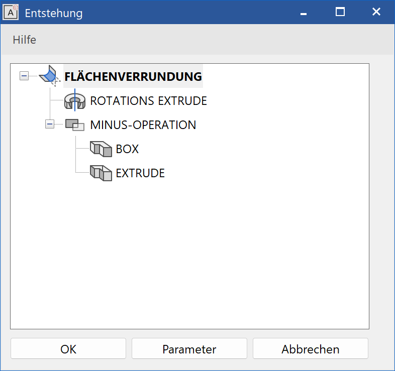
The selected definition (e.g. UNION) is shown highlighted. A tree shows the links to all objects which were used to create the object.
If there is only a single object displayed, the object exists independently of other objects.
Each object is selectable in the tree. Use the PARAMETERS button to display and modify the parameters of the highlighted object (see also MODIFY > 3D object parameters)
Use the buttons and to close the window; the original object is now visible again.
Tip
It is not just possible to change the parameters of visible objects – you can also modify their 2D geometry.
List 3D colours
|
|
Information toolbar |
This function lists the 3D colours used in the design model in the info window.
Modify Facet colour
|
|
*Modify toolbar (ME) |
This function can be used to change the colour of a 3D object or even single colours in a free definition (also special parts from CAD400, DXF or ELITECAD V4) or of special parts from ELITECAD V7.
After activating this function, select the colours to be changed by clicking on them, and assign another colour by entering the colour number or using the menu (m).
Modify 3D colours globally
|
|
* Modify toolbar |
This function can be used to change one colour to another colour for all objects that are visible on the screen.
Select the colour to be changed by clicking on it or entering the colour number. The new colour is then assigned by entering the colour number or using the menu (m).
Tip
The exact description of the colour selection menu can be found in the chapter Pen colours.