Extras Toolbar
Sections
|
|
Extras toolbar |
| Extras menu > Sections |
This function is used to generate a planar section using the current 3D image. The current work plane is always used as the section plane.
The following settings window appears after activating this function. Select the desired option and close the window with  . The intersection is calculated.
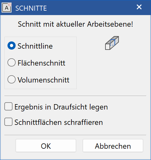
Section line
![]()
Used to create a section profile from 3D objects as a 2D contours. A new 2D object is created for each surface.
Surface section
![]()
Used to trim the current visible objects.
Volume section
![]()
Used similarly to the surface section to trim the current visible objects, whereby additional end surfaces are created.
Place result in top view:
The result of the section can be placed either in the current work plane or in the top view. This option is only possible with section lines.
Hatch section areas:
If this option is selected, hatching is created for the section area with the current hatching parameters. This option is only possible with volume sections.
Tip
The original part (3D model) is not changed. The section is created as a separate object. The current layer name is used for newly created objects. If the layer name has not yet been defined, it is stored with cut. The resulting model receives the attribute object = cutline, cutvolume, cutsurf depending on the section type.
Explosion
|
|
Extras toolbar, view toolbar (ME) |
| Menu Extras > Explosion |
This function is only available in ELITECAD Mechanics and is used to create an exploded view of the currently visible 3D model.
When creating an explosion view the positions of the 3D objects are shifted in space without rotation or resizing. The positions of the 3D objects are scaled relative to the origin of the current work plane.
Different values can be entered for different directions.
Factor < 1 → the design model is shrunk.
Factor = 1 → the design model remains unchanged.
Factor > 1 → the design model is stretched.
A scaling may be reverted by the invers factor (e.g. the factor 2 is inverted by the factor 0.5).
Only visible objects are considered.
This way the design model can be exploded very flexibly by using the function multiple times with different 3D objects visible.
Note
This function is not just intended for visualisation purposes, it changes the design model. 2D elements remain unchanged. 3D definitions change their position. If you want some objects to be keep their position relative to each other, you have to combine them into a special part first.
Join 3D objects
|
|
Extras toolbar |
This function is used to combine 3D objects of a selection into a single new object with 3D information.
The new object is located in the current work plane and belongs to the current layer or classification.
If there are any parametric object in the selection the joint process has to be confirmed.
Tip
The 3D objects that are combined into one special part can no longer be edited in their original form. Only colour, transparency and resolution can be changed for the new object.
Join 3D object to target object
|
|
Extras toolbar |
This function is used to combine 3D objects of a selection into a single object with 3D information.
The only difference to the function JOIN 3D OBJECTS is the fact that the target object has to be selected and will not be created.
After activating the function, the target object is queried. This target object already defines the layer or classification as well as the work plane.
Define special part
|
|
Extras toolbar |
This function is used to combine 3D objects of a selection into a single new object with 3D information.
The following queries appear after activating this function:
2D depiction with Rectangle?
If the 2D depiction of the special part should be drawn with an encompassing rectangle, respond to this query with "Y" Enter . If no 2D
depiction is needed, respond to the query with "N*" Enter .
Tip
The 3D objects that are combined into one special part can no longer be edited in their original form. Only colour, transparency and resolution can be changed for the new object.
Hidden line
|
|
Extras toolbar |
| Extras menu > Hidden line |
This function is used to calculate a 2D image from 3D objects.
The result is converted into a new 2D model and a new layer (hidden line), i.e. copied into the 2D data format and entered in the selected plane.
This new 2D model can now be used with all the 2D functions.
The following settings window appears after activating this function. Select the desired option and close the window with . The 3D image is then calculated as hidden line.
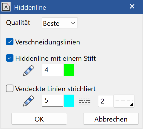
Quality
Here you can select the quality of the hidden line. If you are not satisfied with the result, the quality can be increased.
Intersection lines
If this option is activated, the surfaces of the model are intersected with each other to obtain intersection lines. (Lengthens rendering time!)
Hidden line with pen
Here you can configure whether the 2D image is rendered with a pen or whether the edging colours of the 3D object(s) are used. The pen can be configured.
Masked dashed lines
If you want to include hidden lines in the rendering, this option can be activated. The pen and line type can be configured.
Tip
The rendering only involves the parts of the 3D object that are visible on the screen.