ME Specific Functions
Round edge
|
|
*Modify toolbar, Modify toolbar (ME) |
| Menü Ändern > Kantenrunden |
With this function, the edges of a closed body can be rounded off or chamfered. Depending on the selected setting, individual edges or several connected edges can be edited. Processing takes place either with a constant radius, as a constant chamfer or as a rounding with a variable transition. In addition, various options for editing vertices are possible.
Define edge blend
First, the 3D definition to be edited is selected. If a 3D definition was selected on which edge rounding is possible in principle, the ROUNDING menu appears.
Note
The ROUND EDGES function requires a special description of the model. If the selected definition is not yet available in the structure required for the function, the program will perform an internal conversion. For special parts from older ELITECAD versions (before version 10) or VDA data, the necessary description may not be generated. ROUND EDGES are not possible in such cases.
An edge rounding operation may consist of several individual fillets. To define each single fillet, perform the following steps:
- Select the mode (BEFORE selection)
- Enter required parameter (BEFORE selection)
- Select edge or vertex
- Confirm selection with Enter
Enter without edge or vertex selection completes the entire input and starts the calculation.
Edge blend parameters
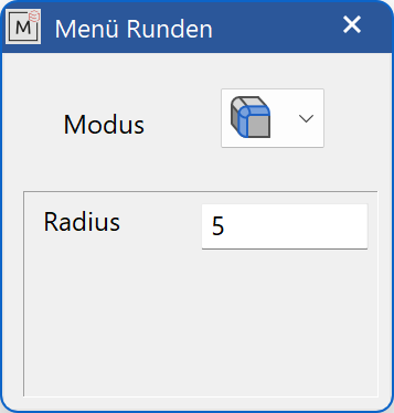
The parameters displayed depend on the current mode.
Blend modes
![]() Blend sequence
Blend sequence
A series of tangentially connected, rounded edges of constant radius.
![]() Vertex blend
Vertex blend
A rounded vertex. Attention: All subsequent edges must also be rounded, either constant or variable. A mixture with chamfers is not possible
![]() Single blend
Single blend
A rounded single edge with a constant radius.
![]() Variable single blend
Variable single blend
A rounded single edge with linearly interpolated radius profile between two specified values (linearly interpolated over the edge length).
![]() Variable blend sequence
Variable blend sequence
A series of tangentially connected, rounded edges with a linearly interpolated radius profile between two given values (linearly interpolated over the entire length).
![]() Single chamfer
Single chamfer
A 45° chamfer running parallel to the edge to be defined. A chamfer is only possible with adjacent planar or cylindrical surfaces.
![]() Chamfer sequence
Chamfer sequence
A series of tangentially connected 45° chamfers running parallel to the defining edges. A chamfer is only possible with adjacent planar or cylindrical surfaces.
Radius
Depending on the mode, this value has a different meaning:
Rounding radius for constant rounding
Starting radius with variable rounding (starting point marked with a box)
Edge distance for chamfers
End radius
The end radius can only be selected with variable fillets.
The variable rounding is interpolated linearly between the start and end radius over the length of the selected edge or edge sequence.
Offset
The offset can only be selected in the mode vertex blend.
The corner surface is set back by this value from the corresponding corner point (marked by a 3D cross). The offset should be larger than the radius otherwise, there will be no effect.
Bulge
A bulge can only be selected in the mode vertex blend.
You can enter comma values from 0 to 2 for the degree of bulging of the vertex blend.
0 → as flat as possible
1 → default
2 → maximal bulge
Define blend
Enter the selection
The edge or corner to be edited is to be selected in the graphics window with the mouse. Depending on the current mode, the program searches for corresponding further edges (for vertex blends all single edges not yet selected, starting from the vertex, for sequences all edges tangent to the selected edge).
Visualise the selection
Edges with defined fillets are clearly enhanced.
GREEN highlighted areas always correspond to the CURRENT SELECTION.
All confirmed selections, the CONFIRMED SELECTION, will be highlighted YELLOW.


Defined vertex blends are indicated with 3D crosses.


For variable fillets, the start points automatically selected by the program are visualised by means of boxes (only visible in CURRENT SELECTION).


Confirming the selection
With Enter the selection GREEN is confirmed. In this case, the previously set parameters are taken from the respective edges or from the vertex.
Modify or delete entry
To be able to change something, there must already be a CONFIRMED SELECTION, that is, any yellow highlighted edges or vertices. You change these as follows:
Set the mode of the selection to be changed (if you want to change a vertex blend, set the vertex blend mode, etc.)
Set new parameters. A radius value of 0 (with variable rounding both radii 0) corresponds to a deletion operation.
Select edge or corner point from the CONFIRMED SELECTION.
If the selection was successful, the associated selection will again be highlighted in GREEN, as in the case of reselection, since this is the CURRENT SELECTION. In addition, a dialog window appears. This displays the old and the new parameter sets.
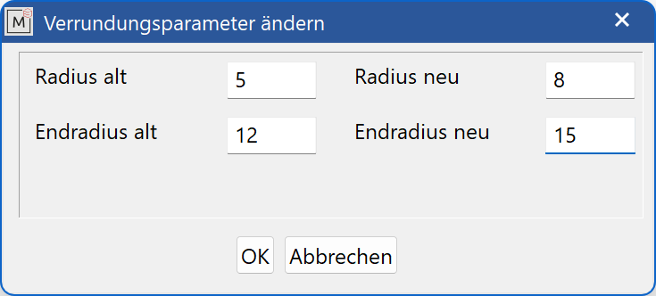
With  the new values are accepted, with
  the old values remain.
If the selection was unsuccessful, the set mode usually does not match the mode of the selected selection. A note about this is displayed below the input line “selection edge belongs to ...”.
Complete edge rounding operation
Enter without edge or vertex selection calls the calculation.
If the algorithm fails due to mathematical (such as radius to large) or algorithmic constraints, the state is restored like it was before the calculation was executed. In this way, parts of the selection can be changed without having to redo the entire selection.
Remarks
A vertex blend corresponds to a rounded corner point. However, this operation is not possible if only one edge belonging to that vertex does not have a fillet. In order to avoid that such cases occur (failure due to a non-selected edge), all unrounded, individual edges of a vertex blend are automatically selected during the selection process. Of course, these edges can be changed individually or even deleted, by addressing them in single rounding mode. Before the calculation, however, all deleted and not reset individual edges of the vertex blend receive the default radius of the assigned vertex blend again, i.e. the value that stood in the selection of the vertex blend in the parameter dialog window.
The temporary deletion of a single rounding involved in a vertex blend is suitable, if one wants to replace the automatically selected single rounding by a rounding sequence (However, it is preferable, first to put on the rounding sequence, and then put a vertex blend on it).
Inaccuracies in the model increase the likelihood of edge rounding failure, if mathematically possible.
Placing vertex blends on corner points where multiple edges converge will sometimes increase the likelihood of a successful rounding operation.
Doubtful fillets, such as rounding off only half of the edge of a cylinder, are indeed partially executed, but do not necessarily provide useful models.
Draft
|
|
*Modify toolbar, Modify toolbar (ME) |
| Menu Modify > Draft |
With this function, the surfaces of a closed body can be inclined by a free angle. The inclination is performed relative to a REFERENCE PLANE, which is either a selected surface of a 3D object or the current work plane.
Define draft
Select 3D definition
First, the 3D definition to be edited is selected. If a 3D definition was selected on which a draft is possible in principle, the reference plane is queried next.
Note
The DRAFT function requires a special description of the model. If the selected definition is not yet available in the structure required for the function, the program will perform an internal conversion. For special parts from older ELITECAD versions (before version 10) or VDA data, the necessary description may not be generated. A DRAFT is not possible in such cases.
Select reference plane
The selection of a reference plane is done by selecting the desired surface in the graphics window, where a confirmation takes place, since this definition remains fixed for the other selections. If confirmed, the reference plane (RED) including the TAPERING DIRECTION, shown as a pyramid in the centre of the surface, is displayed. If no surface is selected by pressing Enter , the current work plane is used as the reference plane, whereby the direction of taper here corresponds to the positive Z direction. This choice is not highlighted graphically, because there is still the option to display the coordinate system.

Note
The difference between choosing a surface and selecting the work plane as the reference plane is that the slope in the first case is around the common edges of reference and selected surfaces, but in the second case the reference plane is around the intersection edges of the work plane with the selected surfaces (these edges stay fixed). The angle of inclination applies relative to the tapering direction in the middle of the reference surface, represented by a pyramid, or, when the work plane is selected as the reference plane, the Z-direction.
Select single surfaces
After selecting the reference plane, the SINGLE SURFACES involved in the draft are selected. The selection is made by clicking on it, which makes it appear in the colour of the CURRENT SELECTION (GREEN). For the newly selected surface, an inclination angle can be specified in the input line. The angle of inclination refers to the tapering direction, which is illustrated either by the illustrated pyramid, or corresponds to the Z-direction of the current work plane. If the CURRENT SELECTION (GREEN) is confirmed with the value indicated in the input line by Enter , it will go to the CONFIRMED SELECTION (YELLOW), assuming the set inclination angle.


Note
If a certain surface of the 3D model has been selected as the reference plane (RED, with pyramid), then all surfaces that are selected for the draft must have at least one common edge with it. Furthermore, all adjacent further surfaces, which are tangential to the selected surface and have at least one common edge with the reference surface, are automatically selected. This is the desired situation in most cases.
If this automatic selection is not desired, then you can specify a suitable work plane as the reference plane. Subsequently, any surfaces can be selected and assigned different values. An automatic selection does not occur in this mode.
Complete draft
When all selections have been made, pressing the Enter key again executes the calculation phase, attempting to perform the draft in the desired form. Should the algorithm fail due to mathematical (such as unrealistic angles) or algorithmic constraints (the surfaces to be tapered must satisfy certain properties in relation to the tapering direction), the state prior to the calculation is reset, including any selection made. This allows parts of the selection to be changed without having to repeat the entire selection.
Modify or delete entry
By re-selecting a surface of the CONFIRMED SELECTION (YELLOW), it can be assigned a new angle of inclination. The surface is again marked in the colour of the CURRENT SELECTION (GREEN); the old value of the inclination angle appears in the input line. The adoption of a new value is the same as in the first selection of the surface. Assuming an angle value 0 in this context means deleting the CURRENT SELECTION (GREEN) from the CONFIRMED SELECTION (YELLOW).
Shadow draft
A special case is the choice of a reference surface (RED, with pyramid) in the 3D model and the selection of another, adjacent surface, which is tangentially connected to the reference surface along the common edge. Because the simple tilting of the selected surface along the edge in is not desired in most cases (this would cause the tangency to be lost), the program interprets this operation as a shadow shape slope.


The angle reference is also done in this case in relation to the tapering direction of the reference surface, the shadow is to fall in the shadow of this direction along the selected surface, tangency is retained here. The SHADOW DRAFT is subject to certain geometric limitations and is not always possible.
Delete surfaces
|
|
*Modify toolbar, modify toolbar (ME) |
| Menu modify > Delete surfaces |
First, the definition to be edited is selected by clicking. Afterwards, the surfaces to be deleted are selected by clicking on them.
The selected surfaces are not only deleted, but the function also tries to close the resulting hole in the body by extending the adjacent surfaces.