Surfaces
Connect surfaces
|
|
Surfaces toolbar |
| Modify menu > Surfaces > Connect |
This function creates a connecting surface between two surfaces. The transition of surfaces to the connecting surface can be tangential or edge-on-edge.
The following queries appear after activating this function:
Transition tangential on both surfaces?
If you confirm this query with "Y"", the transition of the surfaces to the connecting surface is smooth. Enter "N" and the surface is drawn with sharp edges.
Please click on the surface in the 3D view
The points of the surfaces to be connected can be clicked with the mouse.
This surface?
If the surface that has turned magenta is the desired surface, confirm the query with "Y" Enter . However, if the magenta surface is not the desired surface, respond to the query with "N" Enter . In this case, the query Please click on the surface in the 3D view.
Tip
If the transition is not tangential, the first query is Please select definition. Then click on the border curve in the 3D view and confirm that this is correct.
Workshop
Connect surfaces
First, create two surfaces with different heights. The exact description can be found in the workshop DEFINE SURFACE.
 |
Select the CONNECT SURFACE function
Transition tangential on both surfaces?
Confirm with "Y" Enter .
Please click on the surface in the 3D view
Use the mouse to click on the point where you want to connect.
Make sure that you click on the side of the surface that is to be connected.
This surface?
Confirm with "Y" Enter .
Please click on the surface in the 3D view
Use the mouse to click on the other surface to which you want to connect.
Here too, make sure that you click on the side of the surface that is to be connected.
This surface?
Confirm with "Y" Enter .
The connecting surface is created.
| Tangential transition | Non-tangential transition |
 |
 |
Smooth surfaces
|
|
Surfaces toolbar |
| Modify menu > Surfaces > Smooth |
This function is used to create a tangential transition between two trans, design or free form surfaces. The border curves are retained.
The following queries appear after activating this function:
Please click on the surface in the 3D view
Now select the desired surface by clicking on it.
This surface?
If the surface that has turned magenta is the desired surface, confirm the query with "Y" Enter . However, if the surface is not the desired surface, respond to the query with "N" Enter . In this case, the query Please click on the surface in the 3D view. This cycle is continued until positive confirmation is received for the query This surface?.
Please click on the surface in the 3D view [ Enter = calculate]
Here you can select another surface by clicking on it, or smooth the interior of the selected surface by pressing Enter . If another surface is selected, the query This surface? appears again (as described above).
Tangential to the first surface?
If you press "Y" Enter , the first surface is not changed and the second is connected to the first surface tangentially. If you press "N" Enter , the transition to both surfaces is adapted.
Tip
Contour or path must be connected to the start or endpoints.
Workshop
Smooth surface
Draw two trans surfaces from one path and two contours. The exact description can be found in the workshop DEFINE TRANS SURFACE.
 |
 |
Select the SMOOTH SURFACE function
Please click on the surface in the 3D view
Now select the desired surface by clicking on it.
Click on the base surface.
This surface?
Confirm with "Y" Enter .
Please click on the surface in the 3D view [ Enter = calculate]
Click on the other surface and confirm the query This surface? with Enter .
Tangential to the first surface?
Confirm with "Y" Enter .
| Before smoothing | after smoothing |
|
 |
Join surfaces
|
|
Surfaces toolbar |
| Modify menu > Surfaces > Join |
This function is used to connect trans, design or free form surfaces with a common border curve. This is particularly desirable in mould construction, so that one single surface can be formed from several individual surfaces, and this one surface can be shaped or manipulated further.
The result is a new surface and the starting surfaces are deleted. The parameters of the new surface (e.g. colour) are transferred from the first surface selected.
The following query appears after activating this function:
Please click on the surface in the 3D view [ Enter = calculate]
Now select a desired surface by clicking on it.
This surface and parameters?
If you confirm with "Y" Enter , the surface is included in the calculations. However, if the query is confirmed with "N" Enter , the query Please click on the surface in the 3D view [ Enter = calculate] appears again. This cycle is continued until positive confirmation is received for the query This surface and parameters?.
Tip
The connecting surfaces must be selected in the order in which they are to be joined.
The Join surface function works for as many surfaces as you wish, if they share a common border curve.
Otherwise, Join surfaces only works for two surfaces at a time. To connect as many surfaces as you want, you have to repeat the function.
Explanation
If the selected surfaces do not have a common border curve, one of these two messages appears in the info window:
First and second surface have no common border curve. Two of the surfaces have no common border curve.
If joining does not work in principle, the following message appears:
Merge surfaces cancelled.
Workshop
Join surface
Draw two trans surfaces from one path and two contours. The exact description can be found in the workshop DEFINE TRANS SURFACE.
|
|
Select the JOIN SURFACE function.
Please click on the surface in the 3D view [ Enter = calculate]
Click on the base surface.
This surface and parameters?
Confirm with "Y" Enter .
Please click on the surface in the 3D view [ Enter = calculate]
Click on the other surface and confirm the query This surface and parameters? with "Y" Enter .
The function can now be closed with "Y" Enter .
| Before joining | after joining |
|
 |
Lengthen surfaces
|
|
Surfaces toolbar |
| Modify menu > Surfaces > Lengthen |
This function is used to lengthen a surface tangentially.
The following query appears after activating this function:
Please select definition.
Now select a desired surface by clicking on it.
Please click the surface on the desired edge in 3D view
Now the side that you want to lengthen must be specified, by clicking inside the surface.
Lengthen surface?
If the surface that has turned magenta is the desired surface, confirm the query with "Y" Enter . However, if the surface is not the desired surface, respond to the query with "N" Enter . In this case, the query Please click the surface on the desired edge in 3D view appears again.
Please enter length
Now enter the new desired length.
Tip
For trimmed surfaces, a new surface is created which joins tangentially. If the starting surface is not trimmed, the starting surface is lengthened.
Workshop
Lengthen surfaces
Draw a trans surface from one path and one contour. The exact description can be found in the workshop DEFINE TRANS SURFACE.
 |
 |
Select the LENGTHEN SURFACE function.
Please select definition.
Click on the surface you want to lengthen.
Please click the surface on the desired edge in 3D view
Click on the inner edge of the surface.
Lengthen surface?
Confirm with "Y" Enter .
Please enter length
Enter a value (200) and confirm it with Enter .
| Before lengthening | after lengthening |
|
 |
Invert surfaces
|
|
Surfaces toolbar |
| Modify menu > Surfaces > Invert |
This function can be used to reverse the normal vector direction of a surface.
The following queries appear after activating this function:
Please click on the surface in the 3D view [enter = End]
Now select one of the desired surfaces by clicking on it. The selected surface is then coloured magenta.
This surface?
Confirm this query with "Y" Enter and the direction of the normal vectors (displayed in red) is reversed. However, if the magenta surface is not the desired surface, respond to the query with "N" Enter . In this case, the query Please click on the surface in the 3D view [enter = End].
Tip
This preparation of surfaces makes it possible for the radius for all surfaces to be entered with the same sign when performing TRIMMEN/RUNDEN. This prevents errors due to incorrect entries.
Workshop
Invert surfaces
First, draw a box and a slanted surface over three points. The exact description can be found in the workshops DEFINE BOX and DEFINE SURFACE.
 |
 |
Select the INVERT SURFACES function.
Please click on the surface in the 3D view [enter = End]
Click on the slanted surface.
This surface?
Confirm with "Y" Enter .
The function can now be closed with Enter .
| Example with Boolean operation: | |
|---|---|
| Normal vectors upwards | Result after Boolean operation |
 |
 |
| Normal vectors downwards | Result after Boolean operation |
 |
 |
Parallel surfaces
|
|
Surfaces toolbar |
| Modify menu > Surfaces > Parallel |
This function allows you to generate a surface that is the same distance from a given surface at one point.
The following queries appear after activating this function:
Please click on the surface in the 3D view
Click on the surface. It is then coloured magenta.
This surface?
If the surface that has turned magenta is the desired surface, confirm the query with "Y" Enter . If not, confirm the query with "N" Enter . In this case, the query Please click surface on the desired edge in the 3D view appears again.
Please enter offset
Enter the desired distance.
Tip
A positive value is assessed in the direction of normal vectors; a negative value is the reverse.
Workshop
Parallel surfaces
First, draw a slanted surface over three points. The exact description can be found in the workshop DEFINE SURFACE.
 |
 |
Select the PARALLEL SURFACES function.
Please click on the surface in the 3D view
Click on the surface.
This surface?
Confirm with "Y" Enter .
Please enter offset
Enter the desired distance (400) and confirm with Enter .
The parallel surface is displayed automatically.
 |
 |
Outline model
|
|
Surfaces toolbar |
| Modify menu > Surfaces > Outline model |
Use this function to outline any 2D contour on a surface (e.g. fonts, logos, etc.).
Explanation
Following the query *Which model as border (Select point)? ( Enter = Cancel outline), a corresponding 2D model can be clicked on the reference point and entered onto a specific surface.
However, if you want to delete an existing outline model again, you can do so with Enter . Then click on the surface from which the outline model is to be removed.
Tip
For the options APPLY DIRECT and APPLY AS HOLE, the 2D model must be closed. Changes to the shape and position of the 2D model automatically affect the surface.
Options
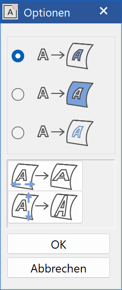
Apply model direct

Use the option APPLY MODEL DIRECT to cut out the surface. The selected model remains.
Apply model as hole

The surface is also cut out with this option, However, the model selected is removed from the surface.
Apply model as curve

When the model is applied "as curve", a 3D curve is created, which you can continue to edit. The surface is not changed.
Adjust horizontally

The selected model is adjusted to be the same width as the surface.
Adjust vertically

The selected model is adjusted to be the same height as the surface.
Tip
When you apply the 2D model without adjustment, an attempt is made to apply the model to the surface to scale (1:1). (For free form surfaces, this is only possible with a distortion). If the model protrudes over the edge of the surface, it is scaled.
Workshop
Outline model
First, draw a slanted surface over three points. The exact description can be found in the workshop DEFINE SURFACE.
Then a circle can be drawn inside the rectangle in a new model.
 |
 |
The following queries appear after activating this function:
Which model as border (Select point)? ( Enter = Remove outline)
The corresponding 2D model can now be clicked on the reference point.
Click on point P1 on the circle in the wire model.
Apply onto which surface (select point)
Now switch to the solid design model and click on point P2 on the surface. This also determines the position of the reference point.
 |
 |
The options window opens.
Now click on one of the following options and confirm the window with  . The surface is cut out.
| Examples: | |
|---|---|
|
|
 |
 |
| Examples with the Adjust option: | |
|
|
 |
 |
Delete trimming
|
|
Surfaces toolbar |
| Modify menu > Surfaces > Delete trimming |
This function is used to restore trimmed surfaces that have been edited using the function TRIM SURFACES. These surfaces are then re-displayed as untrimmed surfaces.
Tip
To restore trimmed surfaces, they must not have been trimmed using the associative function.
After activating this function, select the desired surface by clicking on it. The selected surface is then displayed in magenta. Before it is restored, you must confirm this is correct with Enter .
| Example: | ||
|---|---|---|
| Origin | Surfaces trimmed | Trimming deleted |
 |
 |
 |
Delete single surface
|
|
Surfaces toolbar |
| Modify menu > Surfaces > Delete single surface |
Use this function to delete a single surface from a definition.
After activating this function, select the desired surface by clicking on it. The selected surface is then displayed in magenta. Before it is deleted, you must confirm this is correct with Enter .
Tip
Clicking on the surface again deselects it.
| Example: | |
|---|---|
 |
 |
Surface-division operation
|
|
Modify menu > Surfaces > Surface-division operation |
This function is used to divide connecting free form surfaces. After activating this function, select the desired object by clicking on it.