Create Piping Network
Set load point
|
|
Drainage property bar |
The load points must be set at the upper end of the drainage network.
Horizontally (e.g. for the chamber outlet), vertically (e.g. for the connections to the building drainages fall pipes). The load points must always be set in the same storey.
Load point property bar
The property bar becomes visible if you select the LOAD POINT function to generate a load point or if you double-click on a load point to modify it.

| Function | Description |
|---|---|
| Dimension | |
| Height | |
| Height reference | |
| Select toolbar | |
| Connection type |
Dimension

The load point's dimension can be either selected or entered here.
Height

The base height can be entered here. The unit is dependent on the set height reference. If the load points have been increased or decreased, the height of the connection points is entered. The base height can be read in the grey field.

Height reference
There are three different types of height reference.
Sea level
The entry is in metres above sea level.
±0.00
The entry is in metres above the project null point.
Storey
The entry is from the active storey and in the active unit.
Separate load points
Proprietary load points can be inserted with the SELECT DIRECTORY function.
The functionality is only guaranteed if the necessary attributes are present.
Creating separate load points
An existing load point must be read and modified as a drawing.
From the standard directory <ELITECAD installation directory>\u\<version>\ar\bs\sa\l you can load the load points as a template. It is important that the model is activated under ACTIVATE MODEL before modification. The load point can then be saved under the same in its own library directory.
Connection type
There are three different connection types.
Up
This can, for example, be used to connect a drain pipe to a fall pipe.
Horizontal
This can be used for a chamber output, for example.
Downward
This can be used for a mud drum dip pipe, for example.
Create chamber
|
|
Drainage property bar |
You can use this function to create chambers in 3D.
Chamber property bar
The property bar becomes visible if you select the CHAMBER function to generate a chamber or if you double click on a chamber to modify it.
You can manipulate the main values from the property bar. However, fine-tuning can be done under the chamber parameters.

| Function | Description |
|---|---|
| Chamber parameters | |
 |
Type |
| Geometry | |
| Diameter | |
| Chamber height | |
| Top side | |
| Height reference | |
| Cone type | |
| cone diameter | |
| Cone height | |
| Place |
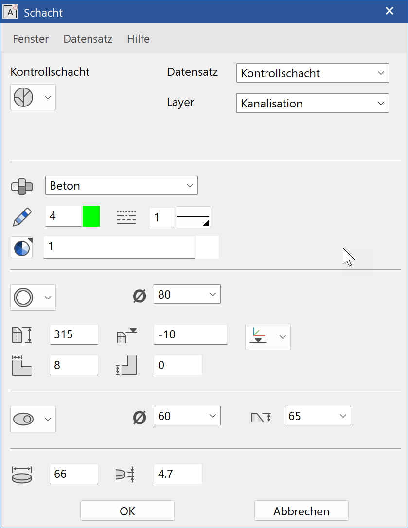
Chamber parameters
![]()
The set-up dialog window for the chamber is opened with the CHAMBER PARAMETER function. The settings of this dialog window are maintained. If the dialog window is closed and reopened, the status most recently set is still in place. If you would like to keep the set parameters for later use, assign it a name in the "Type" field and save it using the RECORD > SAVE function.

Type
The name of the selected parameter record can be found in the "Type" selection box. It can be defined freely and refers to the chamber type. By selecting various types, you can see how the values in all of the other entry fields are automatically modified. This way, once you have saved a chamber type as a custom defined type, you can call it up repeatedly.
To generate a chamber type, simply enter the new name in the text box and modify all the values in the dialog window as desired. Next, you can insert the new type into the selection list using the RECORD > SAVE function. To delete a type that is no longer needed, use the RECORD > DELETE function.
Layer
You can assign a layer to the chamber in the "Layer" field.
Parameters
Material
The chamber material can be selected here.
2D depiction
Here you can select the pen for the 2D depiction.
Line type
Here you can select the desired line type.
3D depiction
Here you can select the pen for the 3D depiction.
Sizes/Dimensions

Shape
Here you can select between circular and elliptical.
Diameter

Here you can select the desired diameter.
Chamber height

The chamber height can be defined here.
Chamber upper edge

The chamber height can be entered here. The unit is dependent on the height reference setting.
Height reference
There are three different types of height reference.
Sea level
The entry is in metres above sea level.
±0.00
The entry is in metres above the project null point.
Storey
The entry is from the active storey and in the active unit.
Wall thickness

The wall thickness can be defined here.
Floor thickness

The floor thickness can be defined here.
Cone

Shape
You can select between none, central or eccentric cone.
Cone diameter

Here you can select the cone diameter.
Cone height

Here you can select the cone height.
Cover

Cover diameter

The cover diameter can be defined here.
Cover height

The cover height can be defined here.
Place
The drawing can be manipulated as needed from the property bar before placement.
Property bar for placement

For more details, see chapter Load and save > Property bar for loading/positioning.
Set library parts
|
|
Drainage property bar |
This function is used for relative loading and placing of library parts. The library parts are aligned to the respective scale when being placed.
For more details, see chapter Load and save > Insert library.
Tip
ELITECAD's library has two subdirectories with complimentary drainage parts for 2D and 3D.
The directory structure is independent of the normal insertions of the library parts.
Create piping
|
|
Drainage property bar |
You can use this function to create piping in 3D. If it is necessary to modify the route of the parts, these can be deleted and redrawn.
Piping property bar
The property bar becomes visible if you select the PIPING function to generate piping or if you double-click on the piping to modify it.
You can manipulate the main values from the property bar. However, fine-tuning can be done under the piping parameters.


| Function | Description |
|---|---|
| Piping parameters | |
 |
Type |
| Diameter | |
| Actual incline (only visible when editing) | |
| Height 1 (only visible when editing) | |
| Height 2 (only visible when editing) | |
| Height reference (only visible when editing) | |
| Polygon functions | |
| Polygon functions | |
| Polygon functions | |
 |
Piping property bar (material) |
 |
Piping property bar (depiction) |
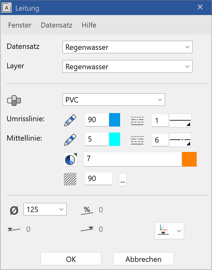
Piping parameters
![]()
The set-up dialog window for the piping is opened with the PIPING PARAMETER function. The settings of this dialog window are maintained. If the dialog window is closed and reopened, the status most recently set is still in place. If you would like to keep the set parameter for later use, assign it a name in the "Type" field and save it using the RECORD > SAVE function.

Type
The name of the selected parameter record can be found in the "Type" selection box. It can be defined freely and refers to the type of piping. By selecting various types, you can see how the values in all of the other entry fields are automatically modified. This way, once you have saved a type of piping as a custom-defined type, you can call it up repeatedly.
To generate a piping type, simply enter the new name in the text box and modify all the values in the dialog window as desired. Next, you can insert the new type into the selection list using the RECORD > SAVE function. To delete a type that is no longer needed, use the RECORD > DELETE function.
Layer
You can assign a layer to the piping in the "Layer" field.
Parameters
Material
The piping material can be selected here.
Perimeter line
Here you can select the pen and line type for the 2D depiction of the perimeter line.
Centre line
Here you can select the pen and line type for the 2D depiction of the centre line.
3D depiction
Here you can select the pen for the 3D depiction.
Hatch
Here you can select the hatch colour for the 2D depiction.
Dimension/incline

Diameter

Here you can select the desired diameter.
Actual incline

A pipe's current incline is shown here.
Height 1

A pipe's current lowest point is shown here.
Height 2

A pipe's current highest point is shown here.
Height reference
There are three different types of height reference.
Sea level
The entry is in metres above sea level.
±0.00
The entry is in metres above the project null point.
Storey
The entry is from the active storey and in the active unit.
Polygon functions
Start piping
![]()
This function can be used to start a new piping circuit.
End piping
![]()
This function can be used to end a piping circuit.
Tip
You can also end a piping circuit by double-clicking or by pressing the Esc key.
Piping back
This function can be used to reset the most recent part without interrupting the function. You can then continue the circuit from this point.
Tip
Parts of a piping network can be deleted by selecting them and pressing Del . Multiple selection is possible with Shift .
Explanation
If a part of the piping network is shown after the slope calculation, the slope calculation needs to be performed again.