Banister Parameters
![]()
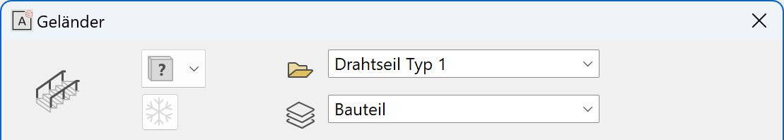
You can open the banister parameters from the property bar or by double-clicking the banister to be modified.

General parameters
 Renovation planning state (only in ELITECAD Architecture)
 Freeze (only in ELITECAD Architecture)
 Type
Type Layer
Layer
The general parameters for architectural objects are described in chapter Architecture objects.
Plan graphics
Exterior banister
The banister can be quantified as an exterior or interior banister.
Room-dividing
If a banister is room-dividing, it is recognized as a boundary when calculating room areas.
2D depiction
Here you can also set whether or not the banister should have a 2D representation. The pen and line type can be determined.
Handrail
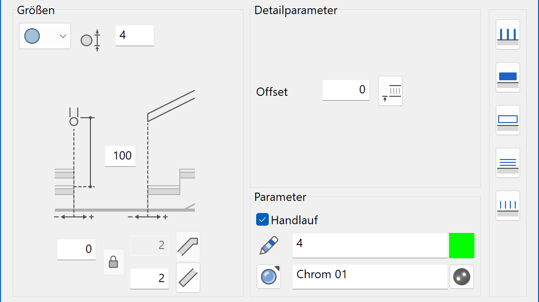
Shape of the handrail

Select from a round, rectangular or free profile.
For a free profile, you have the option to draw any cross section yourself and use it as a handrail.
Tip
The free profile is a self-drawn cross section saved as an ELITECAD file. The cross section must be a closed contour. No 3D definitions! The reference point must always be at the bottom centre when saving.

Handrail height
The handrail height is always measured in ELITECAD Architecture from the top side of the storey floor or from the front edge of the tread on a stair. In ELITECAD Mechanics, the height reference is relative to the active work plane.
Explanation
If a banister is generated from a polygon that is not drawn in the floor plan level, the handrail height is measured from this definition.
Position of handrail
In the floor plan, the handrail is fixed by two dimensions, one for the distance of the handrail axis to the stairway, and one for the start of the handrail in relation to the first step. The end of the handrail is symmetric to the start.
Offset

Using the offset, you can enter a displacement value in the current unit by which to move the reference level in relation to the coordinate origin.
Start and end
Improved · 16 R1 · Improvements
![]()
![]()
![]()
![]()
At the start and at the end of the handrail, an overhang can be specified and whether the overhang is designed with a kink. The lock determines whether the start and end are set to be the same or individually.
Enter height
![]()
Instead of a manual entry for the offset, you can specify a point digitally with the mouse. The measured height from the coordinate origin is entered into the "Offset" field.
Parameters
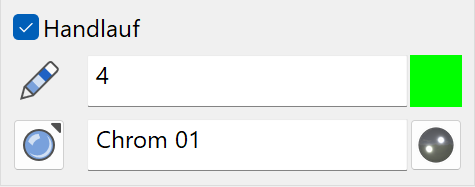
You can switch the handrail on or off using the check box.
You can also specify the pen, 3D colour and material.
Colour mode/material mode
![]()
![]()
This switch allows you to toggle between colour mode and material mode. For more details, see the Colours and Materials chapters.
Newel
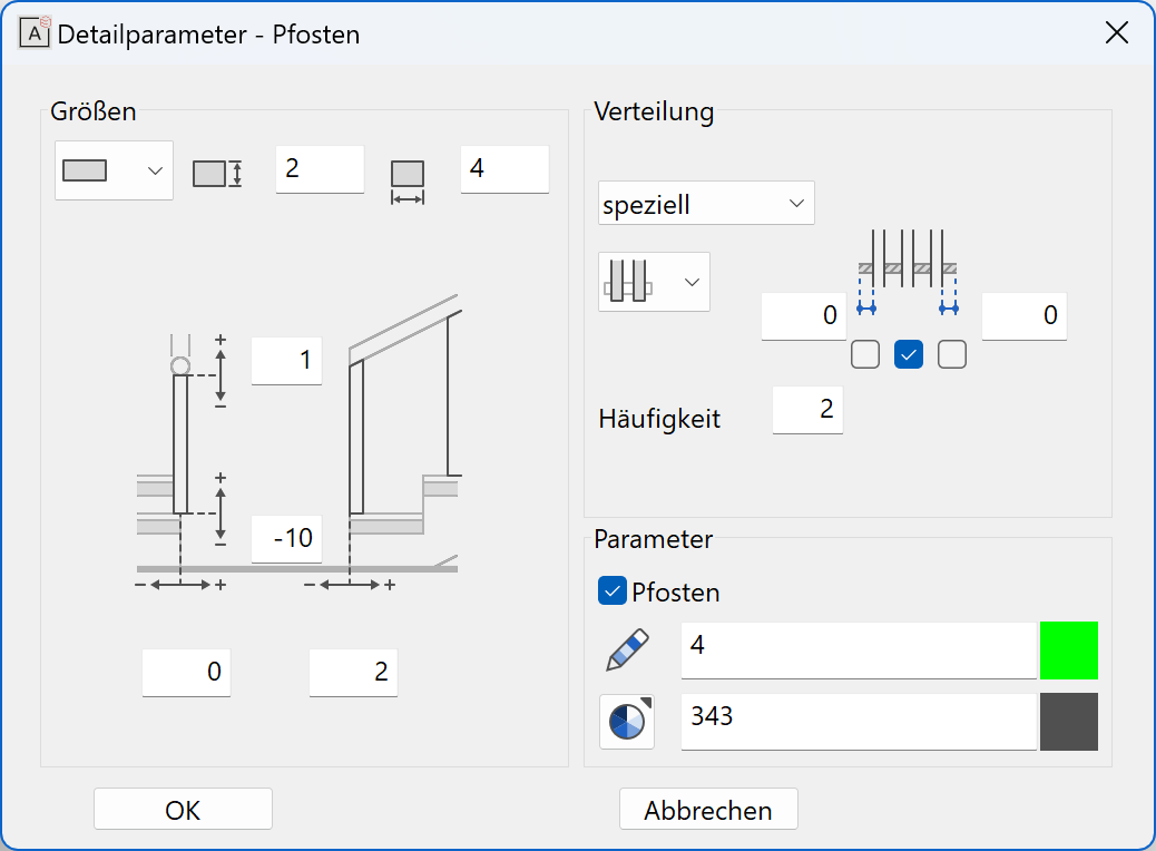
Shape of newel
Select from a round, rectangular or free profile.
For a free profile, you have the option to draw any cross section yourself and use it as a newel.
Tip
The free profile is a self-drawn cross section saved as an ELITECAD file. The cross section must be a closed contour. The reference point must always be in the centre of the contour when saving.
If a 3D part is loaded, this is adopted as newels as a whole. The reference point must also be in the centre and on the underside of the 3D part when saving here.
Position of newel
For the newel top edge, the value 0 is measured underneath the handrail.
For the newel underside, the value 0 is measured flush to an imaginary line connecting the stair edges.
In the floor plan, the newel is fixed by two dimensions, one for the distance of the newel axis to the stairway, and one for the start of the newel in relation to the first step. The end of the newels is symmetric to the start.
Equal distribution
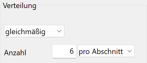
Enter the number of newels, which should be distributed along the banister. "Per side" means that all connected banister parts are divided as a whole. "Per section" applies for each direction modification of the banister anew.
| Per side | Per section |
|---|---|
 |
 |
Distribution over maximal distance
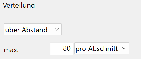
Here you can enter a maximum distance of the newels. "Per side" means that all connected banister parts are divided as a whole. "Per section" applies for each direction modification of the banister anew.
| Per side | Per section |
|---|---|
 |
 |
Special distribution (only active for stair)
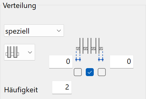
In "special" distribution, you can set newels per step. There are several options, which you can activate with the check box:
Centred newels, newels with distance to step front or back edge, or combined solutions.
![]()
![]()
There are two different options for the bottom edge of the newels.
Here, the frequency determines the number of steps after which the selected newels are set in each case. Value "1" would be for every step.
Parameters
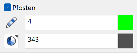
You can switch the panels on or off using the check box.
You can also specify the pen and the 3D colour.
Colour mode/material mode
![]()
![]()
This switch allows you to toggle between colour mode and material mode. For more details, see the Colours and Materials chapters.
Panel
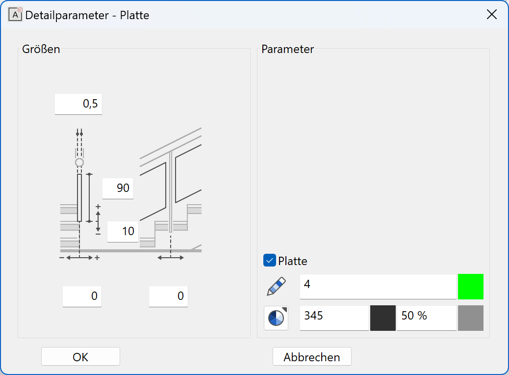
Dimension of panel
The panel thickness can be set.
Position of panel
For the lower panel edge, the value 0 is measured flush to an imaginary line connecting the stair edges. The height of the panel is measured from the lower edge.
In the floor plan, the panels are fixed by two dimensions, one for the distance of the panel axis to the stairway, and one for the distance of the panel from the newel.
Fit to frame
This option can be selected if a frame is defined. The panel is then automatically adjusted to the frame geometry.
Parameters
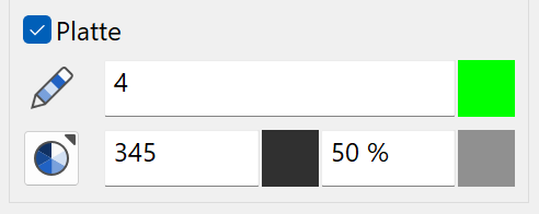
You can switch the panels on or off using the check box.
You can also specify the pen, 3D colour, transparency and material.
Colour mode/material mode
![]()
![]()
This switch allows you to toggle between colour mode and material mode. For more details, see the Colours and Materials chapters.
Frame
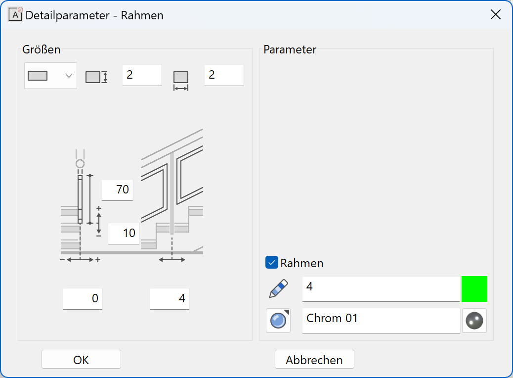
Shape of frame
Select from a round, rectangular or free profile.
For a free profile, you have the option to draw any cross section yourself and use it as a frame.
Tip
The free profile is a self-drawn cross section saved as an ELITECAD file. The cross section must be a successive contour. No 3D definitions! The reference point must always be at the bottom in the centre when saving.
Position of frame
For the frame underside, the value 0 is measured flush to an imaginary line connecting the stair edges. The height of the frame is measured from the bottom edge.
In the floor plan, the frame is fixed by two dimensions, one for the distance of the frame axis to the stairway, and one for the distance of the frame from the newel.
Parameters
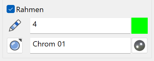
You can switch the frame on or off using the check box.
You can also specify the pen, 3D colour and material.
Colour mode/material mode
![]()
![]()
This switch allows you to toggle between colour mode and material mode. For more details, see the Colours and Materials chapters.
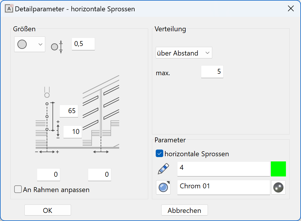
Horizontal balusters
Form of horizontal balusters
Select from a round, rectangular or free profile.
For a free profile, you have the option to draw any cross section yourself and use it as a horizontal baluster.
Tip
The free profile is a self-drawn cross section saved as an ELITECAD file. The cross section must be a closed contour. No 3D definitions! The reference point must always be at the bottom centre when saving.
Position of horizontal balusters
For the bottom edge, the value 0 is measured flush to an imaginary line connecting the stair edges. The height of the horizontal balusters is measured from the bottom edge.
In the floor plan, the horizontal balusters are fixed by two dimensions, one for the distance of the baluster axis to the stairway, and one for the distance of the balusters from the newel.
Equal distribution
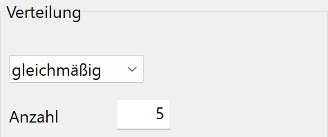
Enter the number of balusters.
Distribution over maximal distance
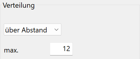
Here you can enter a maximum distance of the balusters.
Fit to frame
This option can be selected if a frame is defined. The horizontal balusters are then automatically adjusted to the frame geometry.
Parameters
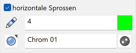
You can switch the balusters on or off using the check box.
You can also specify the pen, 3D colour and material.
Colour mode/material mode
![]()
![]()
This switch allows you to toggle between colour mode and material mode. For more details, see the Colours and Materials chapters.
Vertical balusters
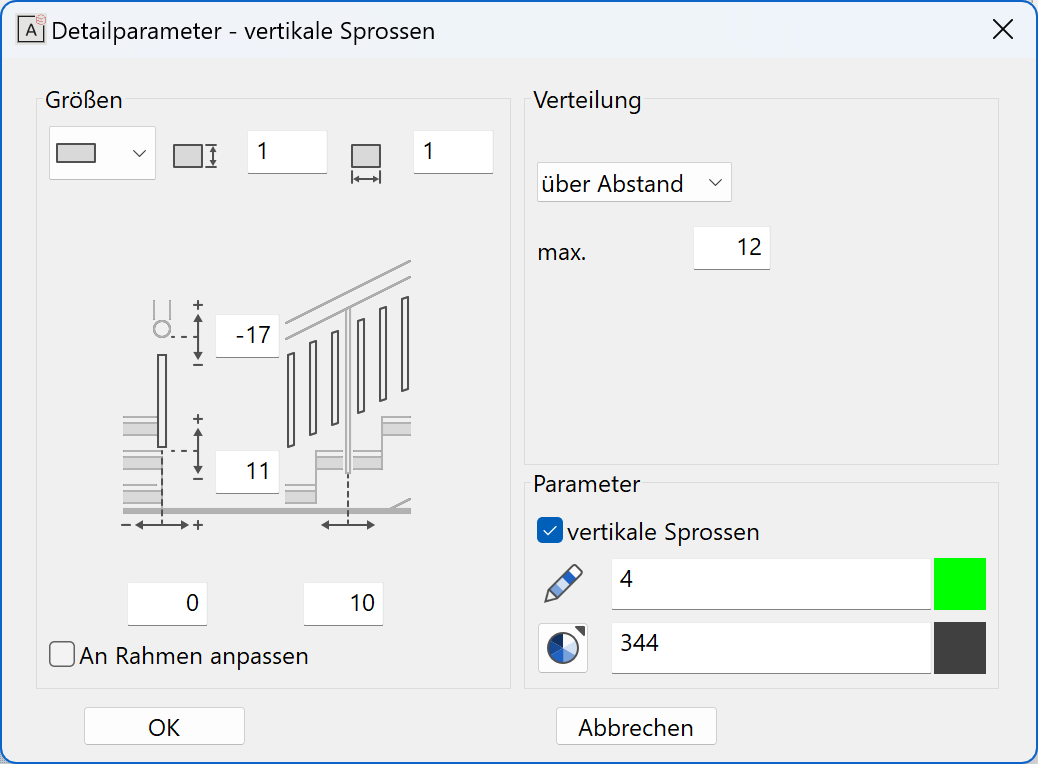
Form of vertical balusters
Select from a round, rectangular or free profile.
For a free profile, you have the option to draw any cross section yourself and use it as a vertical baluster.
Tip
The free profile is a self-drawn cross section saved as an ELITECAD file. The cross section must be a closed contour. The reference point must always be in the centre of the contour when saving.
If a 3D part is loaded, this is adopted as balusters as a whole. The reference point must also be in the centre and on the underside of the 3D part when saving here.
Position of vertical balusters
For the newel top edge, the value 0 is measured underneath the handrail.
For the baluster bottom edge, the value 0 is measured flush to an imaginary line connecting the stair edges.
In the floor plan, the vertical balusters are fixed by two dimensions, one for the distance of the baluster axis to the stairway, and one for the distance of the balusters from the newel.
Equal distribution
Enter the number of balusters, which should be distributed along the banister. The options PER SIDE and PER SECTION are only available if no newels are active.
Distribution over maximal distance
Here you can enter a maximum distance of the newels. The options PER SIDE and PER SECTION are only available if no newels are active.
Fit to frame
This option can be selected if a frame is defined. The vertical balusters are then automatically adjusted to the frame geometry.
Parameters
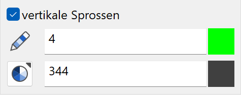
You can switch the balusters on or off using the check box.
You can also specify the pen, 3D colour and material.
Colour mode/material mode
![]()
![]()
This switch allows you to toggle between colour mode and material mode. For more details, see the Colours and Materials chapters.