Glass Element Detail Parameters
Division tool for window, door and glass elements
For glass elements:
As soon as a glass element is selected, the editor dialog window "Tool for window division / muntins" opens.
For windows and doors:
The window/door can already be defined in more detail in the respective parameter dialog before it is applied.
![]()
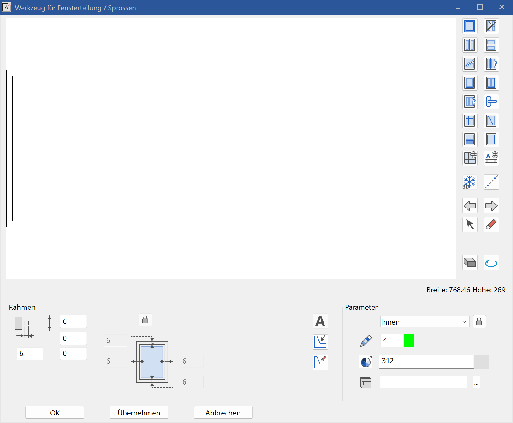
Your current window/door/glass element is always visible in the left preview window in the editor. Divisions, muntins, padding and so on are applied, deleted or selected with the tools on the right-hand side of the dialog window. In the lower area of the dialog window, enter the dimensions and contours of the respective active element. The active element is displayed in magenta.
Preview window
You can work with various ELITECAD functions in the preview window of the editor:
Measure, view as solid/wire model, zoom, and move.
3D freeze
![]()
3D freeze active is the standard setting. If the 3D is not frozen, then the model for doors, window casements and glass elements can be moved/rotated for temporary representations.
Help lines
![]()
This button allows you to draw help lines in the preview window, which help you to place the individual window parts.
Select/edit parts
Select previous part/select next part
![]()
![]()
With these control arrows, you can switch between the individual parts (frame, glass, divisions, casement, muntins, handle, infill, jamb or leaf) to check the settings, make modifications or delete the part.
The selected part is always marked as active (magenta).
Tip
You can also change to solid model for a better view of the active element.
Key combination: Ctrl + D
When making a selection directly in the preview window, using the solid Model is easier.
Select part
![]()
You need to select a particular window part (frame, glass, divisions, casement, muntins, handle, infill, jamb or leaf) in order to edit it. Use the function to select the window part.
The selected part is always marked as active (magenta).
Tip
You can also change to solid model for a better view of the active element.
Key combination: Ctrl + D
When making a selection directly in the preview window, using the solid model is easier.
Delete part
![]()
This function deletes the active part (divisions, casement, muntins, handle, infill, jamb or leaf). The frame and the glass cannot be deleted.
To activate a part, use the SELECT PART function or switch to the desired part using the control arrows.
Solid model switch
![]()
Toggle between solid and wire model with this switch.
180° rotation
![]()
Rotate to the other side of the object in the preview window.
Parameters
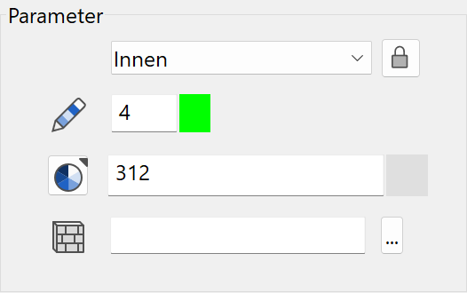
The 2D and 3D depiction, as well as the 3D hatch is identical for almost all parts. For frame, casement muntins, glass, handle, jamb and leaf different visualisation materials can be defined for inside and outside. For the glass, the transparency can also be set.
2D depiction
![]()
2D depiction for the pen and line type for all parts.
3D depiction
The default case is an identical material for inside and outside. In order to define different settings, the lock has to be opened and the setting for outside can be entered.
Colour mode/material mode
![]()
![]()
This switch allows you to toggle between colour mode and material mode. For more details, see the Colours and Materials chapters.
3D hatch

Every sub element of a glass element can be assigned a hatch that appears in the calculated hidden line views.
The default case is an identical hatch for inside and outside. In order to define different settings, the lock has to be opened and the setting for outside can be entered.
Frame
![]()
![]()
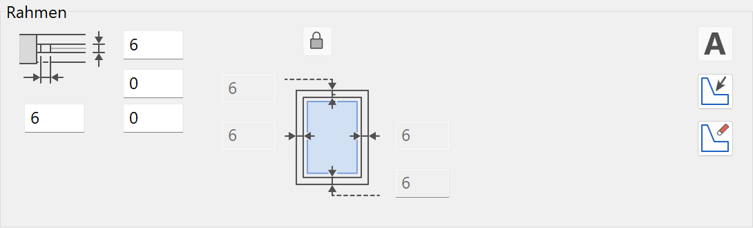
Entry options
- Frame/jamb width, frame/jamb thickness
- Jamb depth for doors only
The default width is equal for all four sides. For individual widths, the lock has to be opened and the widths entered for all sides.
Additional options for windows and glass elements only:
 - Labelling on/off
 - The frame and frame leg are defined by free contour / delete contour.
Division assistant
New · 16 R1 · Improvements
Using the dropdown menu, any of many division options can be selected and then the exact dimensions set.
Tip
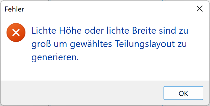
If you get the following error message, you may need to adjust the object dimensions in the window/door/glass element parameters dialog/property bar.
Vertical division
![]()
![]()
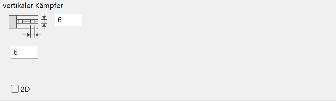
Entry options
- Dimensions
- 2D option for floor plan depiction
It is useful to set a help line for the axis beforehand.
The position in the glass area is determined in the preview window.
When editing a division, the distance from the division axis to the left outer edge of the frame must be specified. This value can be directly adjusted.
Keep in mind that depending on the division width you specify; another casement may be incorporated in the division.
Horizontal division
![]()
![]()
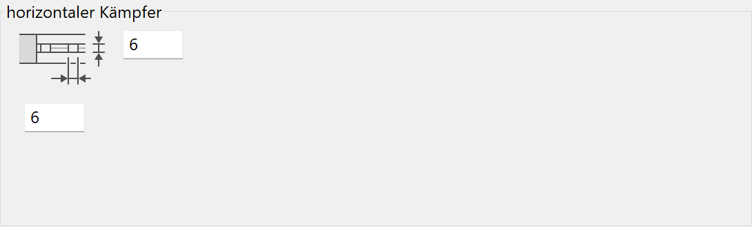
Entry options
- Dimensions
It is useful to set a help line for the axis beforehand.
The position in the glass area is determined in the preview window.
When editing a division, the distance from the division axis to the bottom outer edge of the frame must be specified. This value can be directly adjusted. Keep in mind that depending on the division width you specify; another casement may be incorporated in the division.
Slanted division
![]()
![]()
Entry options
- Dimensions
It is useful to set a help line for the axis beforehand.
The start and end points of the division are entered in the glass area in the preview window. Both points can be placed anywhere on the axis. However, they must not be outside of the window.
Multiple division
![]()
![]()
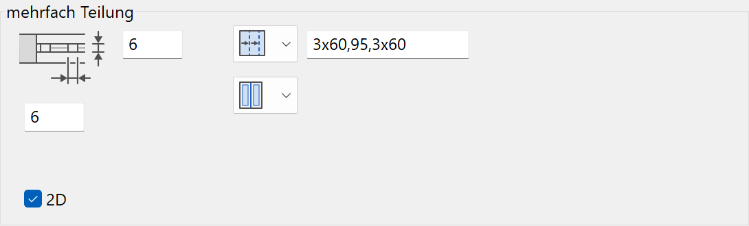
Entry options
- Dimensions
- 2D option for floor plan depiction
- Horizontal/vertical selector
- Distances
Enter the distances (separated by the system delimiter selected in the Options menu) and specify the glass area into which the division must be integrated.
Casement
![]()
Only for windows and glass elements
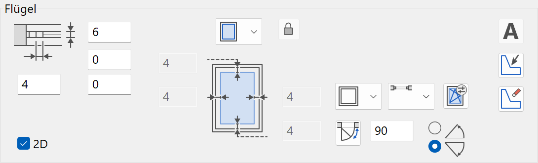
The position of the casement is determined in the glass area in the preview window.
Entry options
- Dimensions and casement offset to frame
- 2D option for floor plan depiction
- Opening symbol of the casement with the detail parameter for the opening symbol
- Floor plan depiction of the opening symbol
Note that the floor plan symbol is only shown if the corresponding opening symbol is also defined. - Angle and direction
- - Labelling on/off
- - Define casement from free contour/Delete free definition.
Window opening symbol
![]()
Casement dropdown selection menu
Depending on the setting in the window division (single or double-casement window), other opening symbols are available.
In the opening symbol parameters formatting settings can be configured depending on the selected symbol.
Single-casement
| Turn or Tilt casement | Turn & Tilt casement | Sliding windows |
|---|---|---|
Double-casement
These symbols are only available in symmetrical and asymmetrical casement types.
![]()
![]()
![]()
Opening symbol parameters
![]()
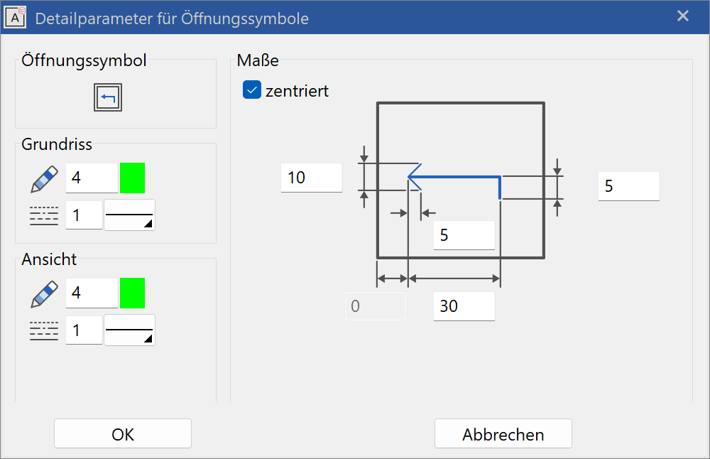
The pen can be set in the parameter. The arrow symbol can be formatted with the sliding door and the lift-up sliding door symbols. If the CENTRED option is activated, the symbol is automatically horizontally centred on the window pane. The symbol is always centred vertically. The dimensions refer to the current dimension unit and the current scale.
No values in this dialog window depend on the representation level.
Symmetric casements
![]()
Only for windows and glass elements
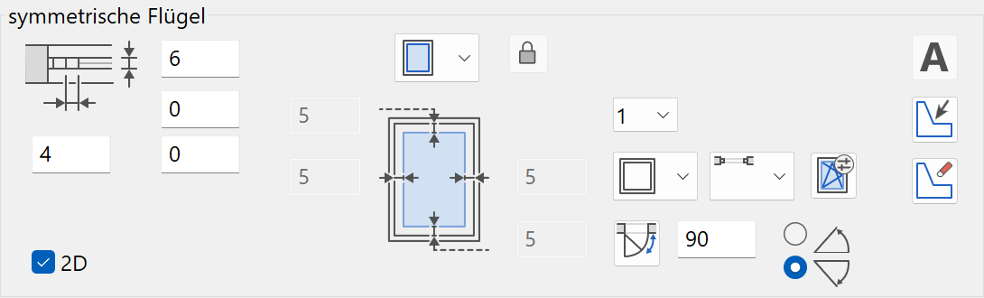
Entry options
- Identical to casement
The appropriate casement is selected by its number.
Asymmetric casements
![]()
Only for windows and glass elements

Entry options
- Identical to casement
The appropriate casement is selected by its number.
In order to define different widths, the lock has to be opened and the width for each casement can be entered. If the width 0 is set, the casement is equally divided.
Door leaf
![]()
Only for doors
Entry options
- Dimensions
- 2D option for floor plan depiction
- Opening or window shape
- Opening angle for 2D depiction
- Define leaf from free contour/Delete free definition
Opening shape
Choose between four options:
Rectangular window
![]()
Lock closed means all sides will be the same distance from the edge. It takes this distance from the field to the left.
Lock open allows for free setting of all dimensions.
Infill – No opening
![]()
Lock closed means all sides will be the same distance from the edge.
Lock open allows for free setting of all dimensions.
Round window
![]()
Using the dimensions, the round window (laboratory window) can be placed anywhere on the door.
If the check box is the ticked, the distance from the edge is ignored and the circle is centred on the door.
Free contour
![]()
A contour can be created in the regular drawing window and when the “define casements from pre-drawn contour” icon is selected, you will be taken to the main drawing window to be able to select the contour.
Tip
It is best if the contour is already drawn to the correct dimensions. Irregular shapes that have their size adjusted in the editor may become distorted.
Handles
![]()
![]()
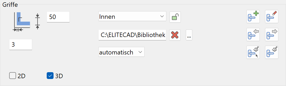
Entry options
The 2D and 3D check boxes activate the handles for 2D and 3D views.
The height and distance are measured relative to the corner.
All four sides of the casement can be selected as the handle position. The option automatic defines the position dependent on the window type.
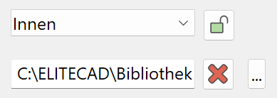
A library part for the handle can be selected or deleted here. The handles can be different for the stop side and opposite side. The default case are identical handles the stop side and opposite side. In order to define different settings, the lock has to be opened and the setting for outside can be entered.
Add handles to all free casements
![]()
A handle is added to all casements, where no handle is defined.
Delete all handles
![]()
All defined handles are being deleted.
Previous handle
![]()
Selects the previous handle.
Next handle
![]()
Selects the next handle.
Copy handle parameters to single handle
![]()
The current parameters are copied to another handle. The target handle is selected by a click.
Copy handle parameters to all handles
![]()
The current parameters are copied to all other handles.
Muntins
![]()
You can click in the glass area to place the muntins.
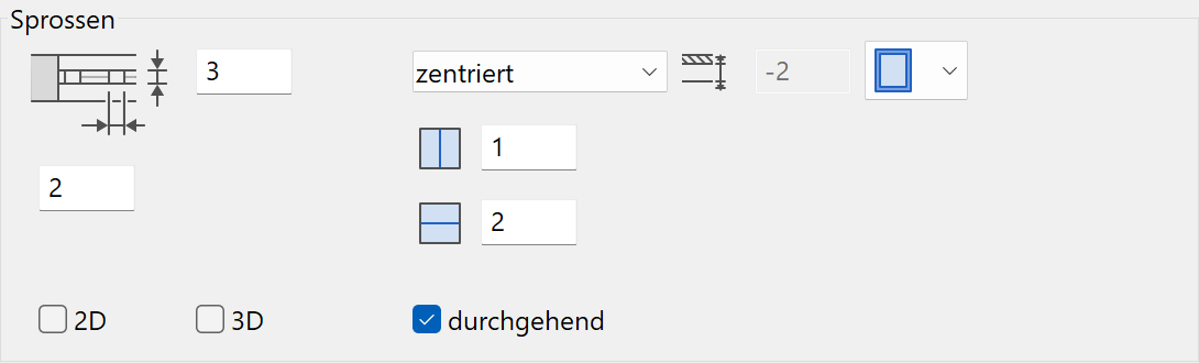
Entry options
- Dimensions
- 2D option for floor plan depiction
- The number of muntins in the x-direction (horizontal) and number in the y-direction (vertical)
The value "0" does not generate any muntins in this direction. - Orientation: free, centred, inside justified, outside justified
- Reference:
- For windows and glass elements: Casement or frame
- For doors: Jamb or edge of door leaf
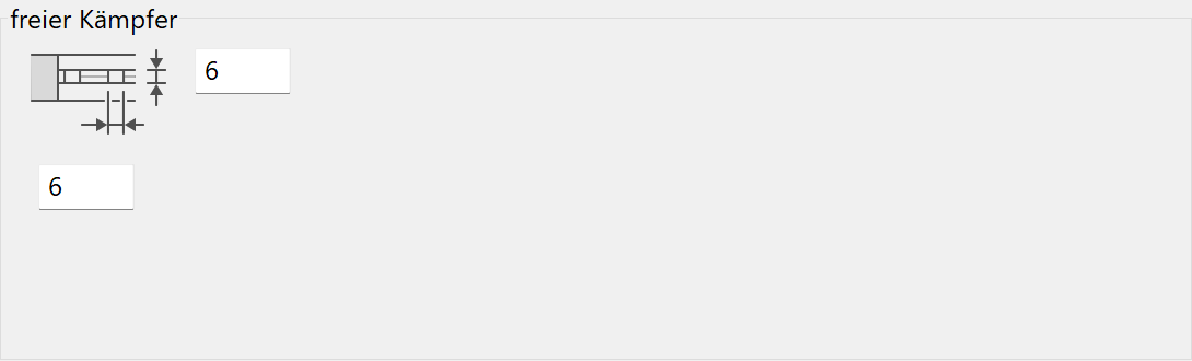
Free muntins
![]()
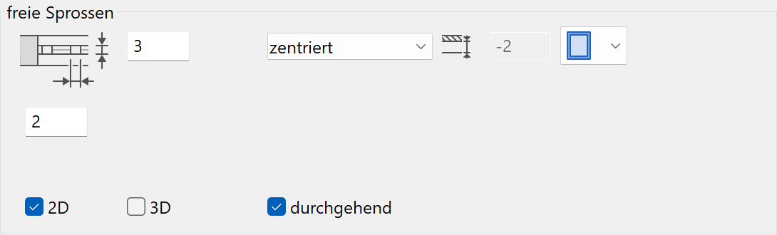
You can click in the glass area to place the muntins.
Entry options
- Identical to casement. Instead of entering the numbers, you have to define the location directly in the preview window.
It is useful to set a help line for the axis beforehand.
The start and end points can be set anywhere on the axis between the frame or casement frame.
Infill
![]()
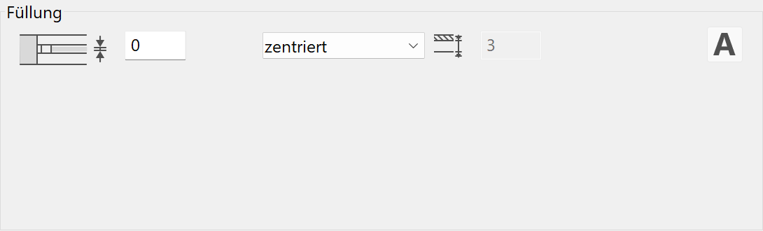
Entry options
- Thickness
- Orientation:
- For windows and glass elements: free, centred, inside justified, outside justified
- For doors: free, centred, stop side, opposite side
- - Labelling on/off
The infill fills a window with a fixed colour. The infill is always between the fixed elements of a window such as frames and transoms. If when defining an infill on a window or glass element there is a casement on the glass part, this is deleted by the program. Additional definitions of muntins are possible.
Glass
![]()
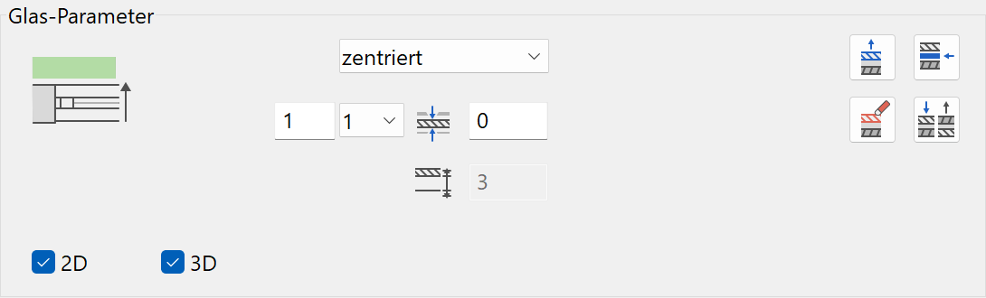
Entry options
- Position of window pane
- Add, insert, delete or swap layers
- Display of number of layers
- Number of active layer
- Thickness of active layer (not depicted in 2D and 3D)
- Display of distance from the interior edge
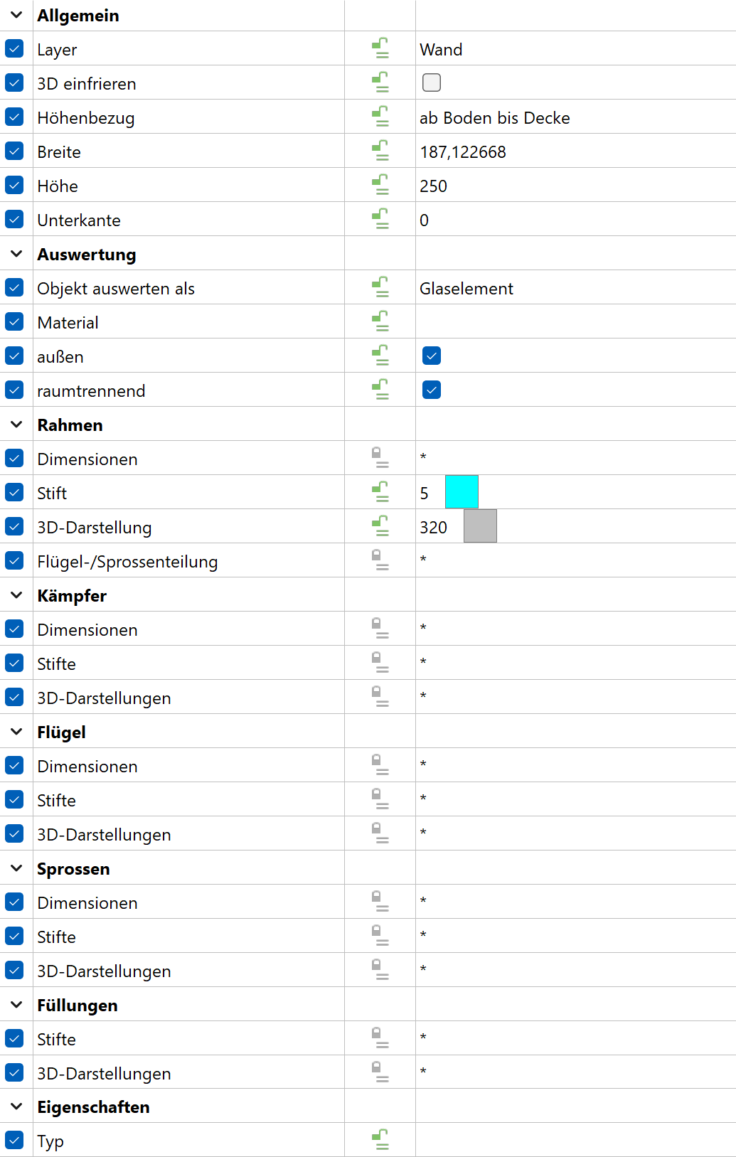
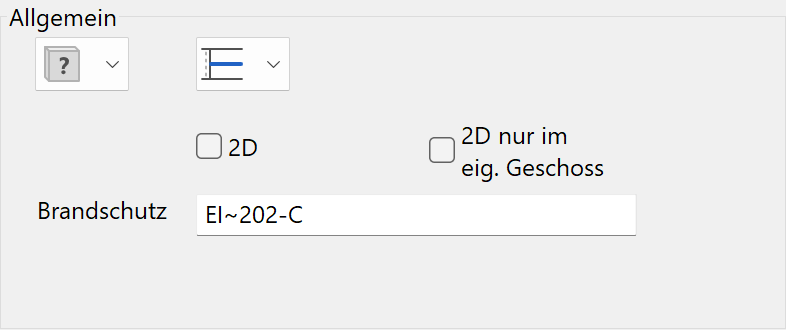
General
![]()
Only in editor for glass elements
Status renovation planning
![]()
The general parameters for architectural objects are described in chapter Architecture objects.
Frame 2D depiction in floor plan
Three profiles are available for selection in the floor plan:
![]() - Simple 2D line. The 3D depiction can be set independent of this.
- Simple 2D line. The 3D depiction can be set independent of this.
![]() - Double 2D lines with frame and casement limitations.
- Double 2D lines with frame and casement limitations.
![]() - Frame and casement with different thicknesses and offsets.
- Frame and casement with different thicknesses and offsets.
2D only in active storey
The 2D depiction for multi-storey glass elements can be either in one specific storey or in multiple storeys.
Fire protection
In addition to the labelling of the glass element, the fire protection class is added.
Any symbol that follows a tilde "~" symbol, will be depicted subscripted. The tilde symbol itself is not depicted.
The "fire protection" field is written into the project book for each report and is used in reports.
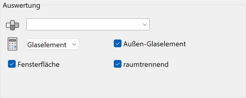
Quantities
Material
The material is taken into account in the report.
Report object as
![]()
The glass element can be quantified as a window, door or glass element.
Outer glass element
Glass element is marked as exterior or interior.
Room-dividing
If a glass element is room-dividing, it is recognized as a boundary when calculating room areas.
Window area
Options for whether the glass element surface should be taken into account in the room label of the window area, and whether it should divide the room or not (not available for windows).
Labelling
![]()
Only in editor for glass elements
The labelling parameters for glass elements are identical with the labelling parameters for windows. The labelling parameters are documented in the chapter Windows.
Copy parameters for windows

Copy parameters for glass element