Roof Window
When you click the CREATE WINDOW function, the settings are copied from the most recently placed window and the window can be placed immediately.
Once the values have been entered in the parameters, a roof surface must be selected for positioning the roof window then the position in the floor plan and finally the direction of the opening are set.
If the roof window is placed on a flat roof, the horizontal orientation can also be determined.
Roof window property bar

The property bar becomes visible as soon as the CREATE WINDOW function is launched or if an existing window is edited.
You can manipulate the main values in the property bar.

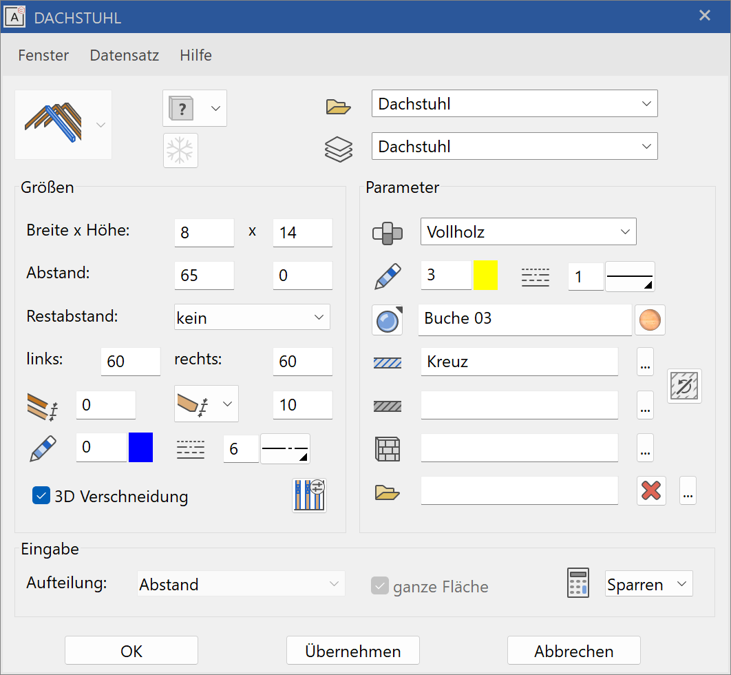
Roof window parameters
![]()
The set-up dialog window for the window is opened with the WINDOW PARAMETER function. The settings of this dialog window are maintained. If the dialog window is closed and reopened, the status most recently set is still available.

General parameters
 Renovation planning state
 Freeze
 Type
Type Layer
Layer
The general parameters for architectural objects are described in chapter Architecture objects.
Material
The material is taken into account in the report. Any name can be chosen from the dropdown or simply entered into and confirmed with Enter . If you want to remove a name from the dropdown list, enter it with a preceding minus sign and confirm with Enter .
Dimensions
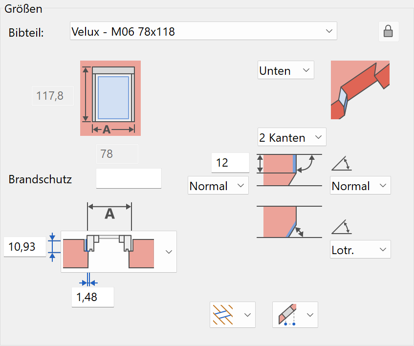
Library part
| Predefined window | free window |
|---|---|
 |
 |
Here you can either select from a list of predefined windows (library part in combination with predefined manufacturer dimensions) or you can select a library part using a free mode and the desired dimensions can be freely defined.
The free Lib parts with the corresponding attributes are stored under
<ELITECAD installation directory>\u\<version>\ar\glob\l\roofwindow\slant, or
<ELITECAD installation directory>\u\<version>\ar\glob\l\roofwindow\flat.
Stop

The installation depth and also the frame bearing area for roof windows can be determined here.
Parameter
Active side
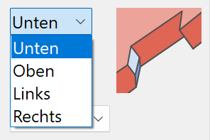
The settings in the dialog window always refer to the active side.
Number of edges
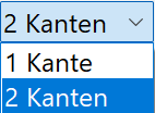
A side can consist of one edge or two edges. All sides should have the same number of edges to avoid geometric errors.
1 edge


An edge can run in four ways. Any angle can be entered with the "Angle" option. If the opening does not have enough space in the roof with the specified angle, the edge is created vertically.
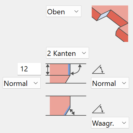
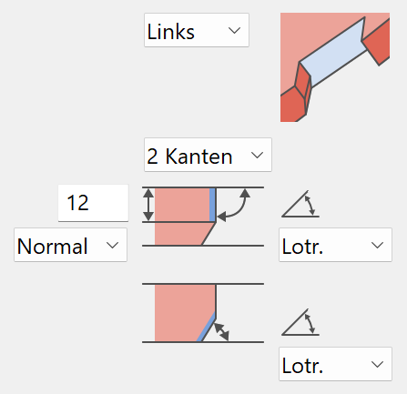
2 edges
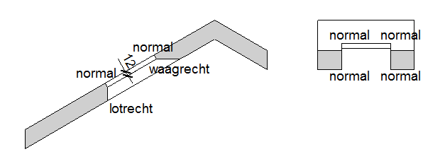
The lengths can be determined for the first edge. You can select how the length is measured. An edge can be horizontal, but the distance is measured normally to the roof surface. All sides should have the same length to avoid geometric errors.
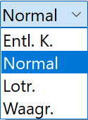
One of the four alternatives for the edge course can be selected for each edge length.
Example of an opening with two edges. Both "right" and "left" sides are also defined with two edges, although one edge would suffice.
| Cross section | Long section | ||
|---|---|---|---|
 |
 |
 |
 |
A warning appears if the edges do not meet at the corners.

Keep stops:
In this case, you will have to consider geometric errors.
Adjust stops:
In this case, a dialog window appears with all of the settings for each side. You can decide which stop should be used as a reference.

Trimmer
![]()
![]()
Here you can decide whether a trimmer should be drawn for the roof cut-out.
The trimmer distances correspond to the manufacturer's information but can be adjusted if necessary. The trimmer parameter dialog window opens if only the trimmer is edited.
Description in the Truss chapter.
Entry:
The roof window can either be set in the floor plan or placed above the height of the bottom edge. If the roof height or inclination is changed, the roof opening is refreshed according to the entry.
Position by floor plan
![]()
Position by height

The height of the roof at any point can be measured with the HEIGHT IN POINT function.
Window shape
Roof window
![]()

Flat roof window
![]()

Window detail parameters
![]()
![]()
![]()
Here you will find additional settings options for an individually customised window.
Each of the buttons shown leads to another separate set-up dialog window.
Padding
![]()
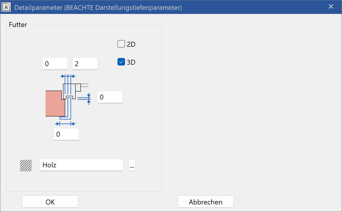
The distance, thickness, width and lengthening can be entered.
The 2D and 3D check boxes activate the padding for 2D and 3D views.
Covering frame - Joint
![]()
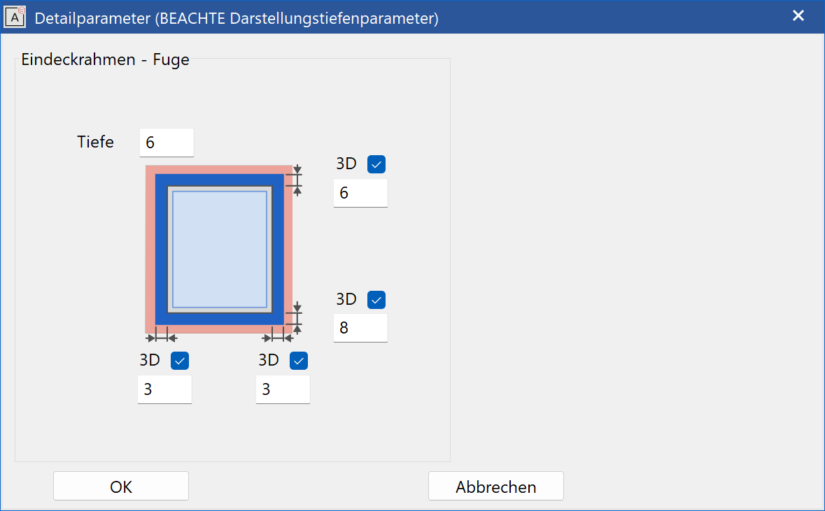
A depth and the distances can be entered.
The 3D check boxes activate the joint for 3D views.
Labelling parameters
![]()
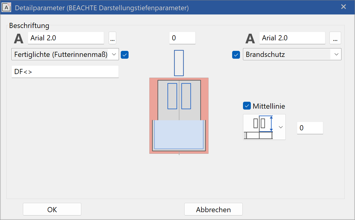
Label
The text parameters are selected from the general parameter database.
A pre-text and a placeholder with < > for the value calculated by the CAD are entered in the label field.
With < P > a m, cm/mm dimensioning is used.
Dimensioning text
Activation using the check box beside the menu. The font parameter is selected above the menu. A format specification can be entered in the label field below the menu. The frame dimension, the raw clearance or the finished clearance (lining dimension) can be labelled.
Fire proofing labelling (top right)
- "fire proofing" is oriented along the centre line
- "fire proofing rotated" is oriented perpendicular to the centre line
In the second menu, the text parameter can be selected.
The check box enables or disables fire-proofing labelling.
The fire-proofing class is entered in the main dialog window.
Centre line
Here, the length of the centre line can be entered absolutely or relatively to the length of the label.
| Representation without centre line | Representation with centre line |
|---|---|
 |
 |
2D/3D depiction
 |
 |
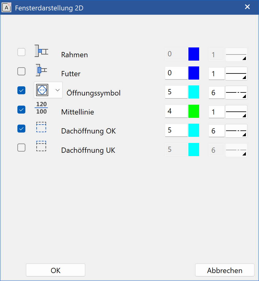
2D depiction
Setting the pen and line type 2D depiction for all window parts activated in the dialog window. The 2D can be switched off with the check boxes.
The grey background means "undefined".
This makes the components of the window immediately apparent.
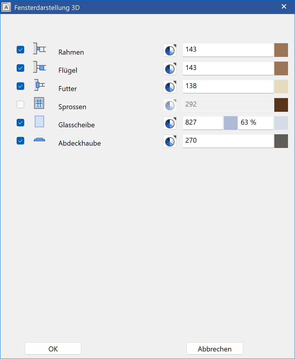
3D depiction
For frame, casement and window pane different visualisation materials can be defined for inside and outside. The default case is an identical material for inside and outside. In order to define different settings, the lock has to be opened and the setting for outside can be entered.
Colour mode/material mode
![]()
![]()
This switch allows you to toggle between colour mode and material mode. For more details, see the Colours and Materials chapters.