Window detail parameters
Here you will find additional settings options for an individually customised window.
Each of the buttons shown leads to another separate set-up detail parameter window.
Tip
Various settings in the detail parameter windows depend on the representation level. This means that when the representation level is refreshed, the windows will be regenerated and adapted to the settings in the representation level.
Representation levels create the conditions for covering several planning phases with one design model. This means that by changing the representation level, the window can be provided with a profile representation for the input planning which differs from that in the work planning. This always relates to the same window.
If the representation level is changed or refreshed (SETTINGS > REPRESENTATION LEVELS) and "Refresh design model + views" is confirmed with  then the presettings of the representation level are adopted.
In order to express this dependency clearly, the respective sections of the representation level dialog windows are listed in addition to the detail parameter windows shown below.
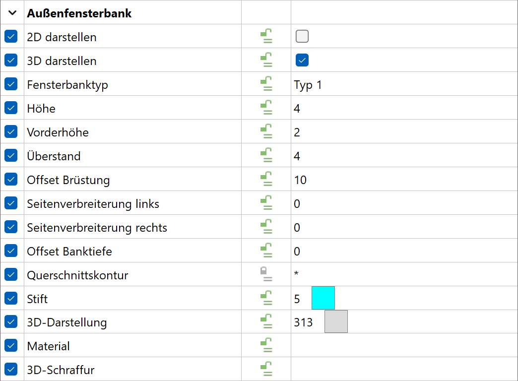
Outer sill
![]()
![]()
![]()
![]()
![]()
Window sills of type 1 and 2 are in front of the window frame.
Window sill type 3 corresponds to the French construction type.
Window sill type 4 is for windows, which open outwards.
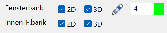
The 2D and 3D fields activate the window sill.
If 2D is activated, the lintel line is shown with pen 0 (=not printed).
The side widenings can have different values on the left and right.
Low window sill (type 1)
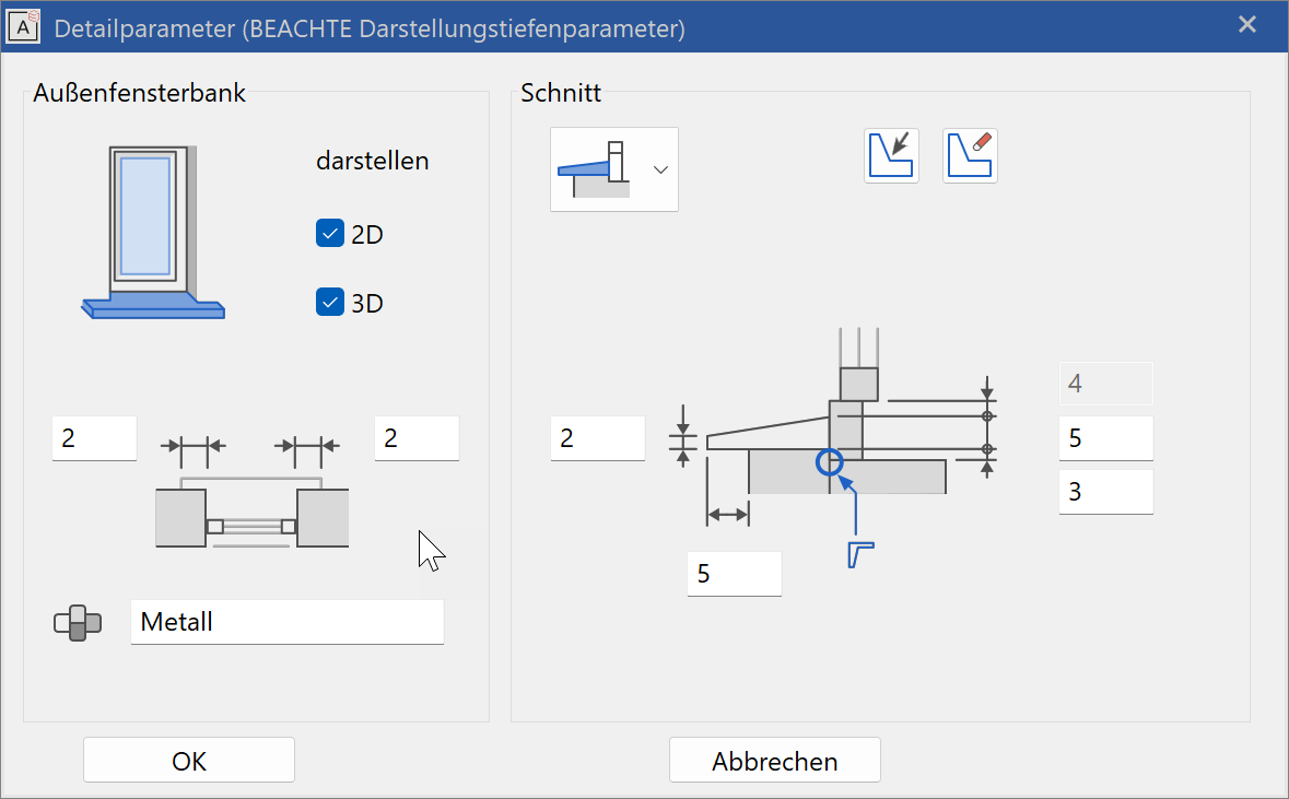
The cross section is defined with front height, sill height and projection.
"Parapet offset" defines the difference in height between the bare parapet on the inside and outside.
The value with a grey background shows the protrusion of the top edge of the frame over the window sill.
High window sill (type 2)
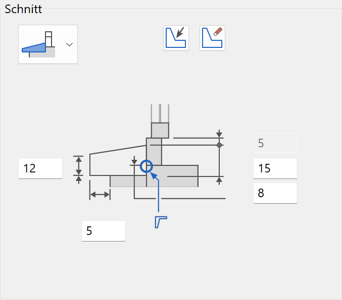
Entries the same as type 1
France window sill (type 3)
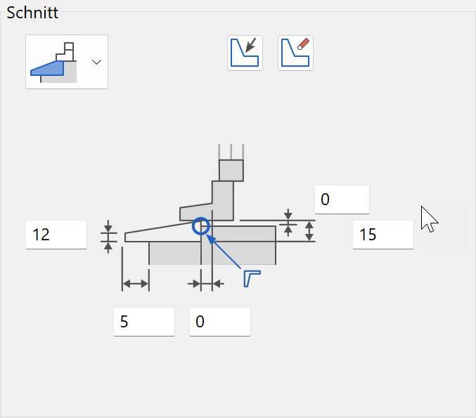
The cross section is defined with the front height and the height, the projection (offset) and the distance to the frame line ("sill depth offset).
"Parapet offset" defines the difference in height between the bare parapet on the inside and the top edge of the window sill.
Window sill for windows which open outwards (type 4)
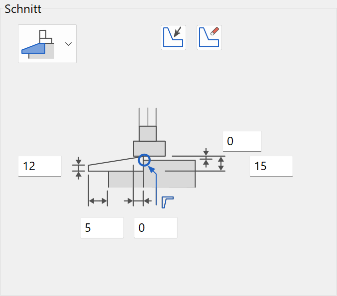
Entries the same as type 3
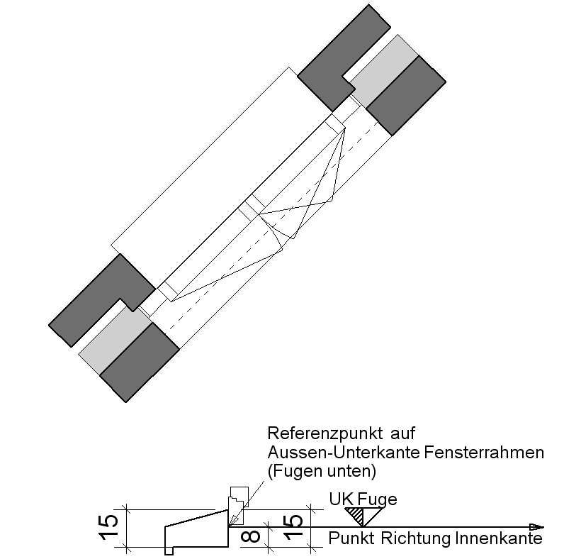
Create sill from free contour
- Before the free contour can be defined as a window sill, the dimensions and positions must be preset in the detail parameter.
-
Draw the window sill contour in the floor plan according to the main dimensions of the existing window sill. The contour should remain upright regardless of how the window axis is lying in the floor plan.
-
Edit window (click on the window) and open the WINDOW PARAMETERS set-up dialog window.
- Start definitions with the button "Define window sill from free contour" in the outer sill detail parameter.

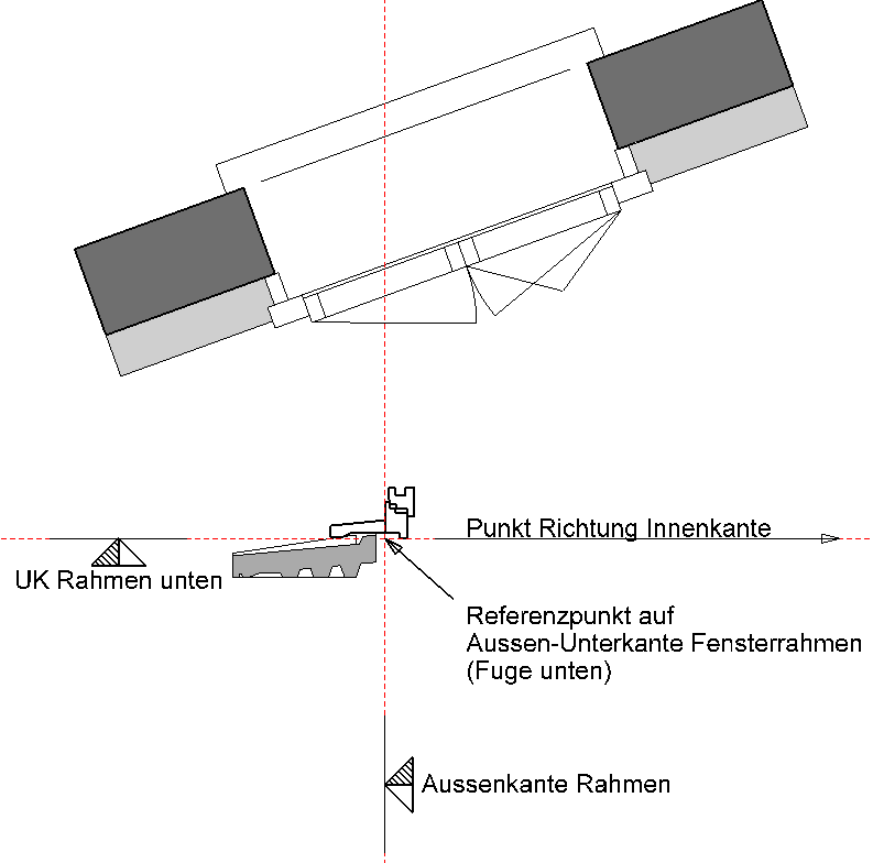
- Capture point of reference (exterior, bottom edge of joint below).
- Define any point in the direction of the inner edge.
- Close all set-up dialog windows by clicking .
Alternatives when defining
![]()
With the WORK PLAN ON SURFACE function, click on the surface of the frame side.
Draw the frame contour in this work plane and then proceed as above.
Note
This window can be saved as a parameter.
The sill depth is also fixed when modifications are made to the w-frame depth (in wall).
The values cannot be changed in the outer sill detail parameter, with the exception of the side widenings.
Delete free window sill
![]()
The window sill is reset to a standard cross section using the "Delete free contour" button.
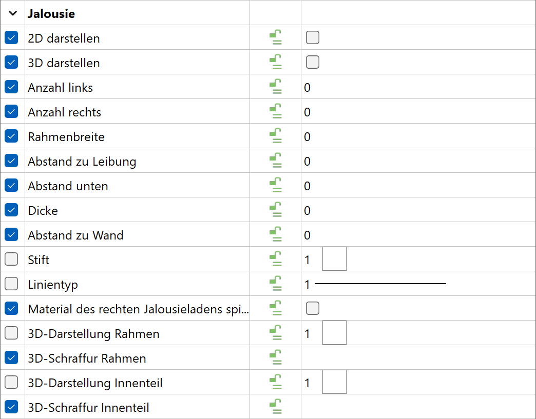
Representation levels parameters
Representation in 2D/3D and the 2D depiction pen depend on the representation level.
Copy parameters
Inner sill 
![]()
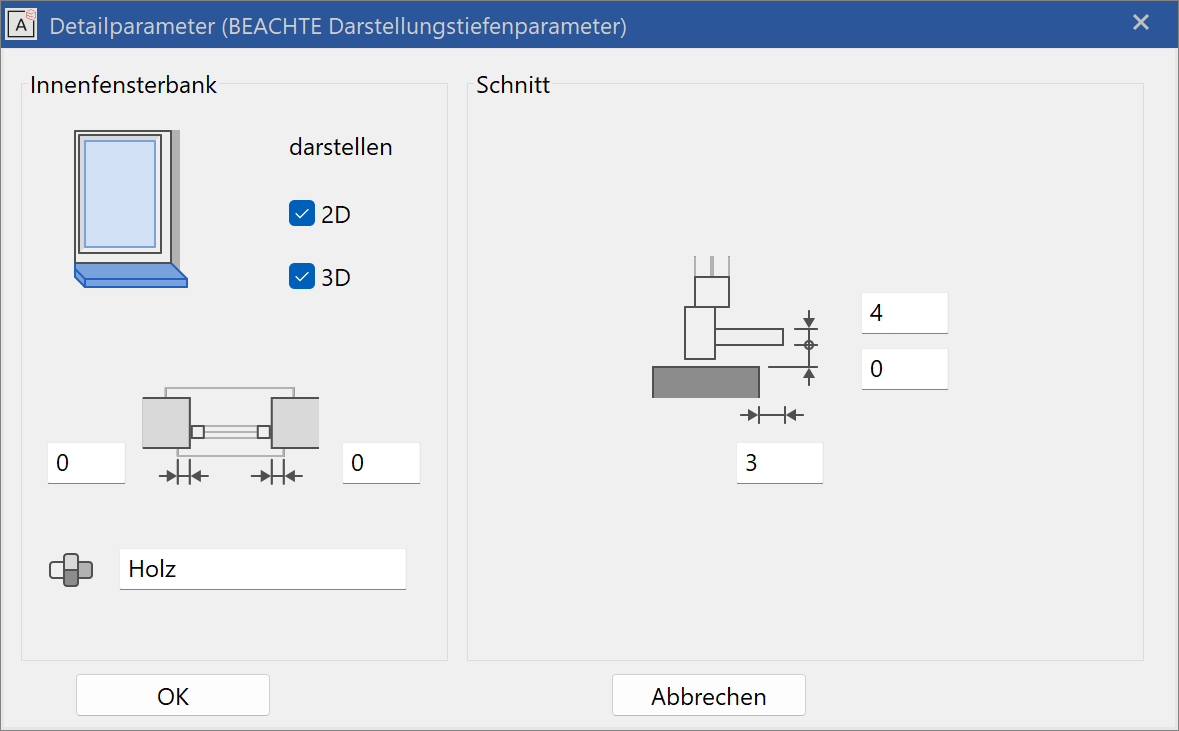
The 2D and 3D check boxes activate the window sill for 2D and 3D views.
If 2D is activated, then the 2D depiction of the lintel is switched off.
If there is no inner sill (e.g. a tiled parapet in a bathroom), then neither 2D nor 3D should be switched on.
The following does not apply for the country setting France and Switzerland:
"Take thickness as plaster" should be activated for finished dimensions from the top edge of the inner window sill. Otherwise, the sill height is set to 0 cm. This means that both the finished parapet height and the finished clearance can be set correctly.
Side widening 

The side widening can have different values on the left and right.
Inner sill from free contour 
An inner sill can be defined as well as the frame leg in the w. frame parameters.
Representation levels parameters 
Representation in 2D/3D and the 2D depiction pen depend on the representation level.
Copy parameters 

Window frame parameters
![]()
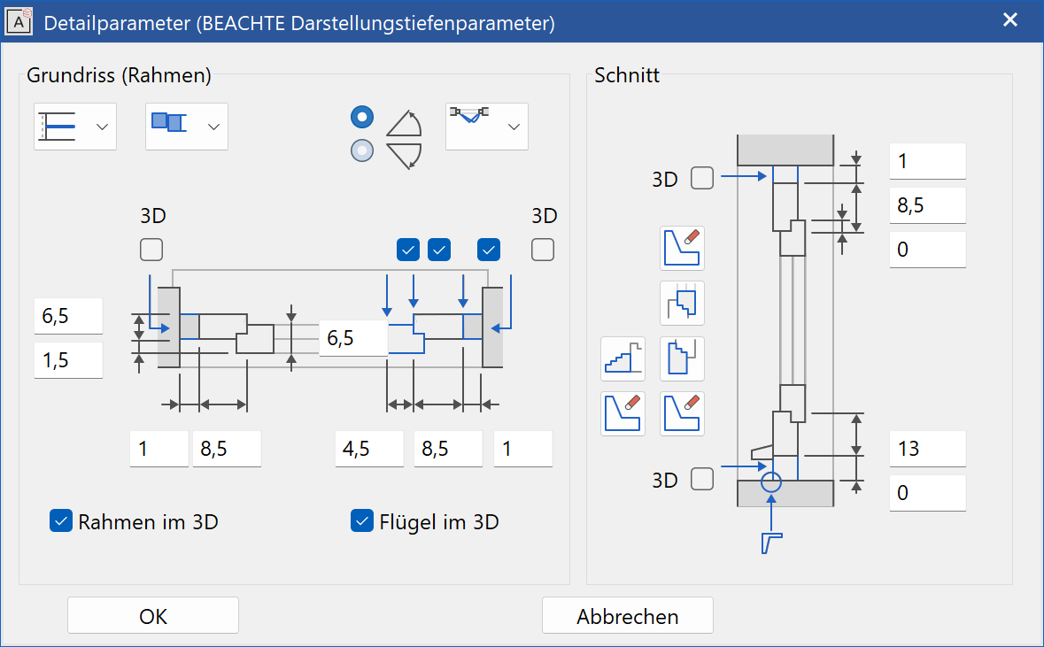
The floor plan detail and a section of a window are shown in the dialog window.
2D depiction in floor plan (W.frame)
Three profiles are available for selection in the floor plan:
![]() - Simple 2D line. The 3D depiction can be set independent of this.
- Simple 2D line. The 3D depiction can be set independent of this.
![]() - Double 2D lines with frame and casement limitations.
- Double 2D lines with frame and casement limitations.
![]() - Frame and casement with different thicknesses and offsets.
- Frame and casement with different thicknesses and offsets.
Copy parameters

Style of the casement stop
![]() - Offset measured from the outer edge of the window.
- Offset measured from the outer edge of the window.
![]() - Offset measured from the inner edge of the window. (specifically to aid with sliding doors and windows)
- Offset measured from the inner edge of the window. (specifically to aid with sliding doors and windows)
Frame settings
The check boxes for casements, frames and joints affect the 2D depiction in the floor plan. The side joints are displayed in 3D.
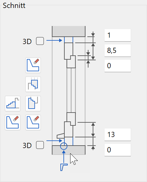
In the section, you can use the check box to select whether the joint should be displayed in 3D for the top and bottom joints. For a type 5 roll blind lying above, the joint widths above the roll blind height should match.
W-frame in 3D and Casement in 3D switches the entire representation of the window profile in 3D on or off (when switched off, glazing can be generated in the raw window cavity!)
Copy parameters
Opening symbol floor plan
![]() - No symbol
- No symbol
![]() - Turn casement 1/3 open
- Turn casement 1/3 open
![]() - Turn & tilt casement 1/3 open
- Turn & tilt casement 1/3 open
![]() - Turn casement open
- Turn casement open
![]() - Turn & tilt casement opened
- Turn & tilt casement opened
Copy parameters
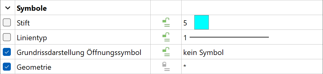
Opening direction


Opening inwards or outwards
Define frame, limb and casement frame from free contour
- Before the free contour can be defined, the dimensions and position must be preset in the detail parameter.
- The profiles are created using the desired detailing. The contours should remain upright regardless of how the window axis is lying in the floor plan. Each contour must be an individual polygon.
- Using help lines, fix the frame outer edge and bottom edge of the frame.
Example: French window construction with padding - Edit window (click on the window) and select Frame in the window parameter detail parameter.
- Start definitions using the contour button.
- Capture point of reference (exterior, bottom edge of joint below).
- Define any point in the horizontal direction of the inner edge. The contour is adopted with
 .
. - Close input window with .

Window defined with free contours for window sill + window frame
Note
The contour is adjusted to the required width for different window frame widths (according to the frame detail parameter).
An inner window sill can also be defined with the sides of the frame.
The contours can also be defined using the window editor.
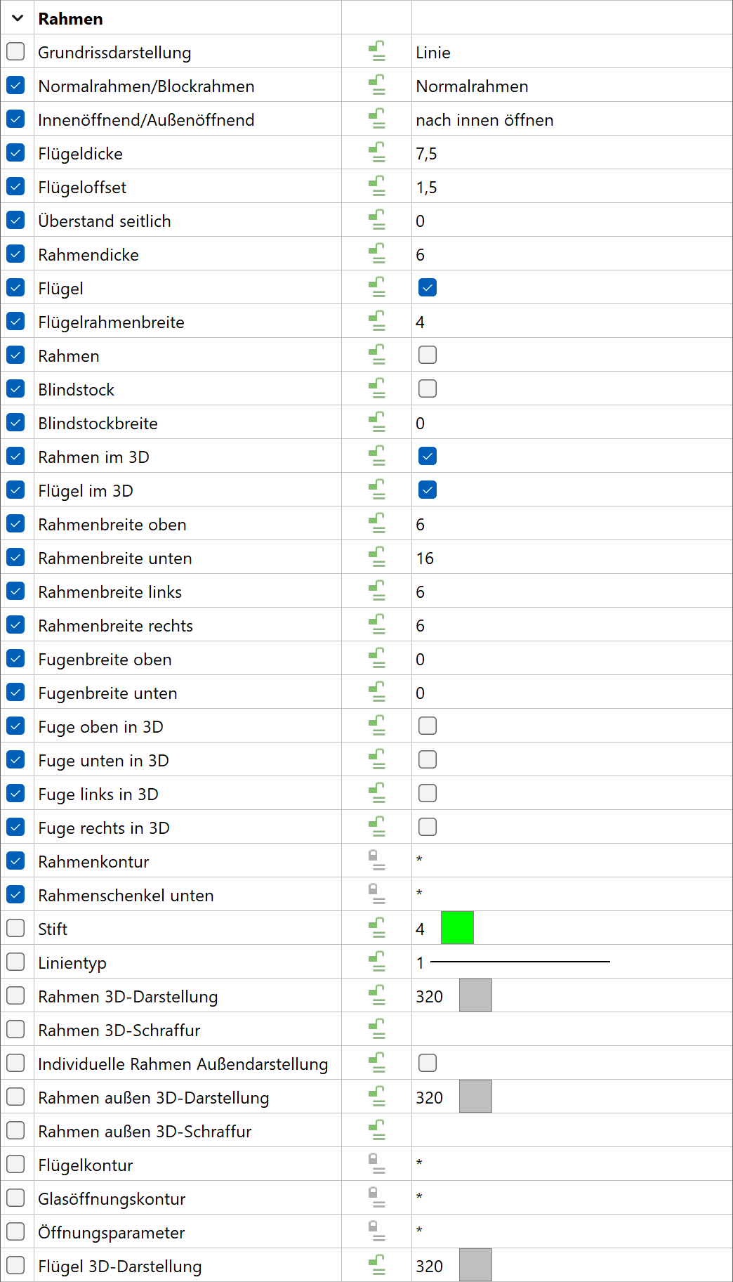
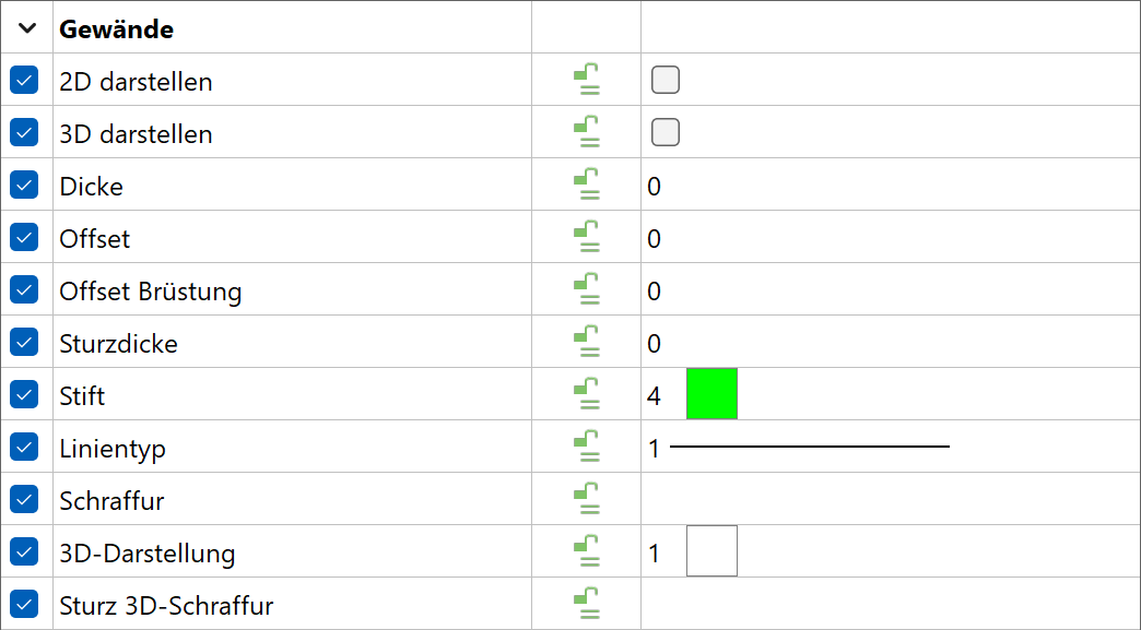
Representation levels parameters
All profile depictions including the profile pen depend on the representation level.

Assembly frame + padding
![]()
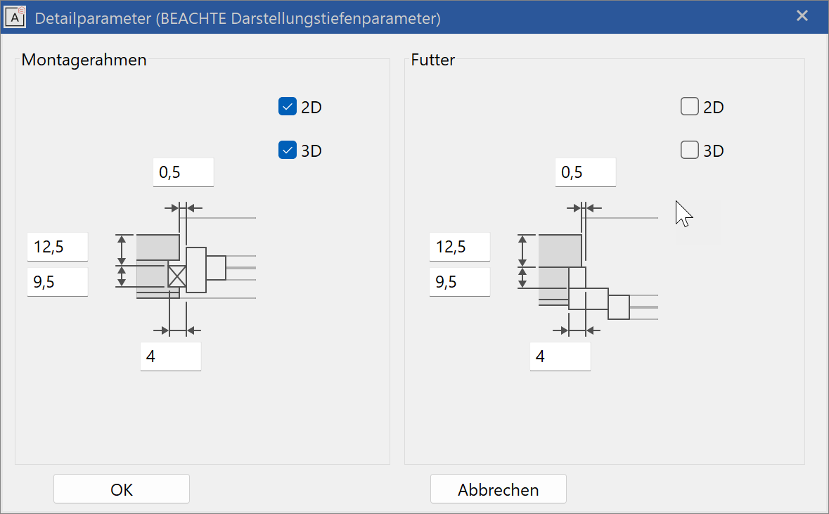
An assembly frame or padding can be specified using this dialog window.
Assembly frame

An assembly frame can be defined on the four sides of the window frame.
The position is determined by the distance to the window frame (joint/net offset) and by the depth (offset).
The cross section is given from the width and the thickness.
The 2D and 3D check boxes activate the assembly frame for 2D and 3D views.
The assembly frame can also be used for a dummy frame.
Padding
Padding can be defined on the side and at the top (see illustration in last chapter).
The position is determined by the difference to the outer gross dimension (joint / net offset) and by the depth (offset).
The cross section is given from the width and the thickness.
The 2D and 3D check boxes activate the padding for 2D and 3D views.
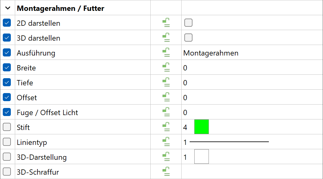
Copy parameters
Roll blind/net curtain
![]()
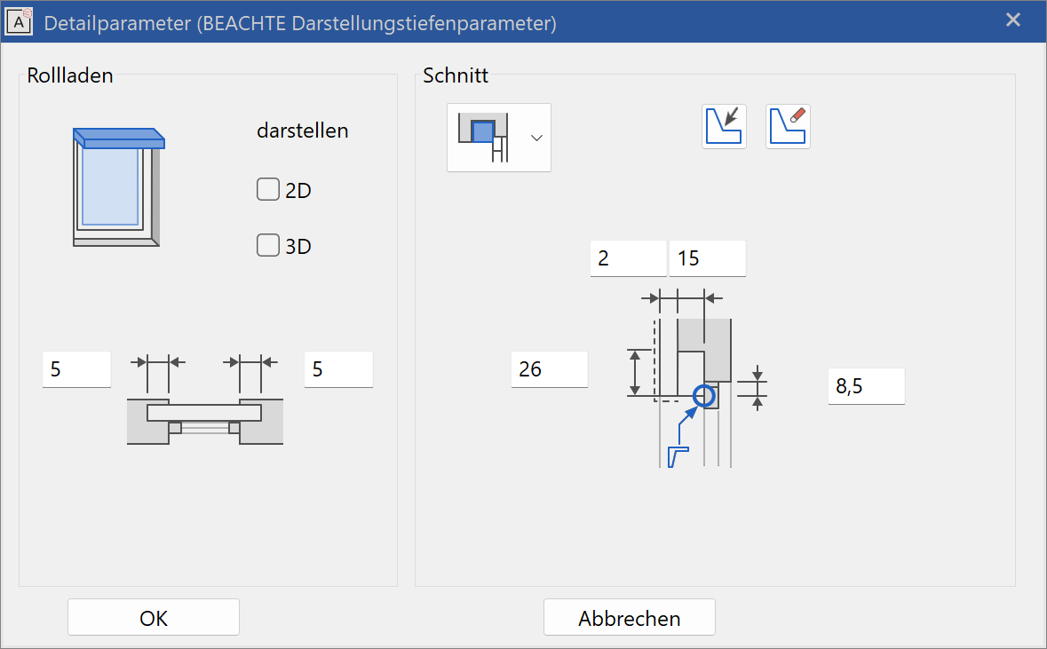
The 2D and 3D check boxes activate the roll blind for 2D and 3D views.
Side widening

The side widening can have different values on the left and right.
Types
![]() - Type 1 on facade outer side
- Type 1 on facade outer side
![]()
![]() - Type 2 + 3 on outer side of frame
- Type 2 + 3 on outer side of frame
![]() - Type 4 for renovations between lintel and frame
- Type 4 for renovations between lintel and frame
![]() - Type 5 for external insulation and back-ventilated facade, position freely definable
- Type 5 for external insulation and back-ventilated facade, position freely definable
![]() - Type 6 over the frame, for solid angle constructions
- Type 6 over the frame, for solid angle constructions
Roll blind on facade (type 1)

The offset causes the position to be adjusted to the finished net clearance.
Roll blind on outside of frame (type 2)


The offset can also be larger than the cabinet height (illustration on right).
No wall layers are imported in the lintel in type 2 (centre illustration).
Reference marker for opening dimension and height marker:
Gross lintel inside and bottom edge of cabinet (net lintel height).
Roll blind on outside of frame (type 3)


For type 3, the wall layers are imported according to the STOP setting.
Roll blind between window frame and lintel (type 4)

The top edge of the window frame is automatically adjusted due to the cabinet height.
Roll blind position freely definable (type 5) for walls with external insulation


Roll blind type 5 is particularly suitable for facades with external insulation.
The cabinet can be positioned on the outer side of the frame (e.g. for gathered slat blinds) or can lie above the frame (roll blind).
The entry style differs somewhat from the other types as a result.
- Offset: Value for the difference between finished clearance and gross clearance.
The offset must equal the cabinet height for roll blinds above the frame.
This dimension determined for the offset is important for the entry of gross clearance and finished clearance, as well as for the opening dimension. - The position of the cabinet is independent of the frame.
- If the roll blind cabinet is above the frame and the lintel over the cabinet, the cabinet height must be entered for the joint above and for the offset.

Reference marker for opening dimension and height marker:
Gross lintel inside and bottom edge of the cabinet (net lintel height) = bottom edge of insulation.
Roll blind with angle (type 6)

Roll blind type 6 is suitable for solid constructions.
Reference marker for opening dimension and height marker:
Gross lintel exterior and cabinet height
Inside label: The reference height for the lintel height is measured for the top edge of the cabinet.
Select free roll blind contour
![]()
The button “roll blind by free contour” allows defining a free cross section by a previously created contour. The reference point is indicated in the image.
Delete free roll blind contour
![]()
The button “delete free contour” resets the roll blind to the standard cross section.
Copy parameters

For all types, the offset is the difference between gross lintel and the bottom edge of the roll blind (net lintel height).
Lintel parameters
![]()
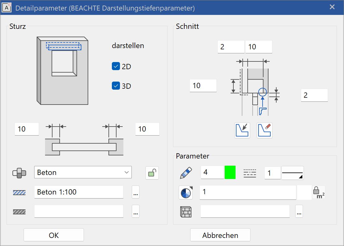
Depiction
The lintel can be switched on and off on 2D and 3D in the left column.
Side widening
The lintel can be extended left and right individually.
Dimensions
The cross section is defined in the section region. The cross section could also be a free profile.
Parameter
The lock is used to link the 3D colour with the room. The visible surfaces of the lintel are depicted with the material of the room.
Open: Room parameters have priority.
Closed: Material of the room parameters is not considered.
Colour mode/material mode
![]()
![]()
This switch allows you to toggle between colour mode and material mode. For more details, see the Colours and Materials chapters.
3D hatch

A 3D hatch that appears in the calculated hidden line views can be assigned.
Blind case
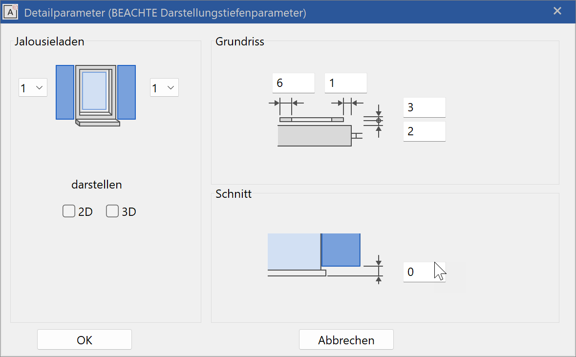
The 2D and 3D check boxes activate the blind case for 2D and 3D views.
The position is determined by the distances to the wall and reveal.
The shape is given by the window frame width and the thickness.
The CAD calculates the blind width and height from the settings of the window opening and the number of blinds.
The 3D hatch is set as the blind infill and can be seen in views and sections.
Copy parameters
Window walling
![]()

![]()
This is activated with the stop for the window walling.
The lintel thickness, side thickness and walling offset produce the side and upper cross section depending on the W-frame depth (in wall).
The window sill is determined with the window sill height, front height and offset.
The difference from the inner to the outer parapet is entered for the parapet offset.
The cross sections are hatched in the floor plan and section using the hatching parameters.
Copy parameters
The side widenings of the window sill are not active for the walling.
Stop editor
![]()
Stop editor in the window parameters
![]()
![]()
![]()
![]()
![]()
Selection of stops in the window parameters
![]()
![]()
![]()
![]()
![]()
Open the stop editor to select the stop in the property bar:
- Without stop
- Stop for solid construction
- Stop for facades with external insulation
- Stop for window walling
- Stop for walls with internal insulation
The stop editor can be opened directly in the property bar.
The gradient of the individual wall layers in the stop area depends on the wall construction and the stop type. As the wall composition is yet unknown when placing a new window, there is no preview and you cannot yet configure those settings.
The correct layer gradient of the wall can only be determined when the existing window is edited.
Depending on the stop type chosen, the stops are defined differently by the CAD.
The stop detail editor consists of the preview and the list of the individual wall layers.
Preview
A preview first appears when you edit a window.
It is preferable to work in contour mode: Ctrl / Strg + K .

The OPTION menu defines which region is displayed in the preview window.
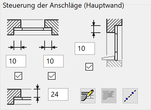
Main wall / Side wall
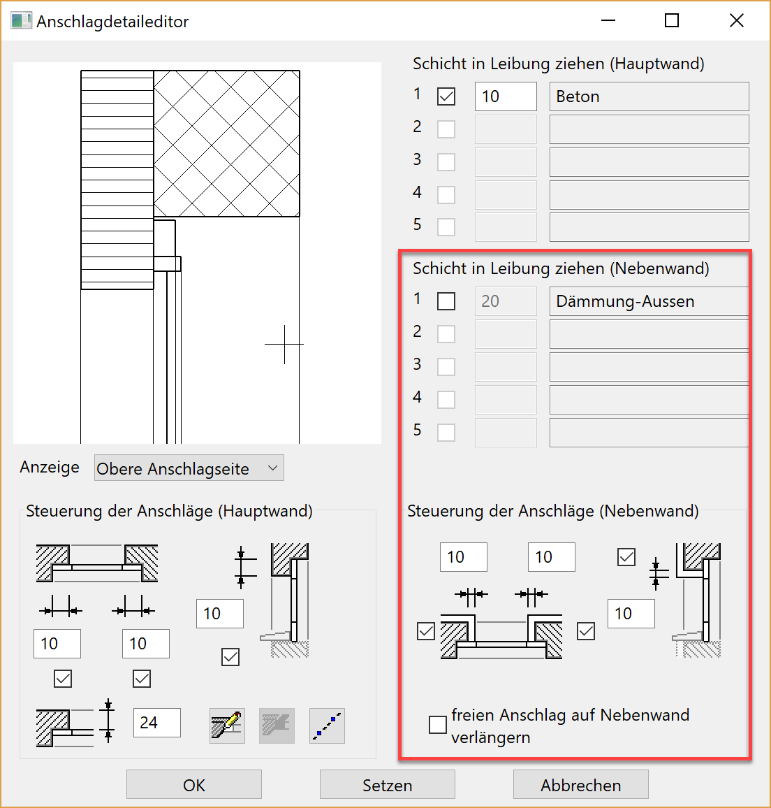
The red marked area is only active if a side wall exists. Here the stop settings for a side wall can be configured.
The settings for the main wall are configured below the graphics window and for the main wall layers right beside the graphics window.
Stop for solid constructions
![]()
![]()

For the stop for solid construction, the external layer is wrapped around the corner with the layer thickness whereas the insulation is cut out.
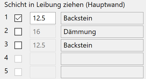
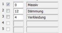
List of wall layers
The wall layers are listed here. This list is only correct if you edit a window; when you place a window, the last values are always shown, as the program assumes that you are placing the window in the same wall.
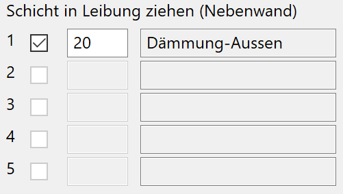
In the column "Draw wall layer into reveal", you can decide for each layer with a tick in the check box whether the respective layer should be drawn into the reveal.
For each individual layer, the value of the thickness with which the layer goes into the reveal can also be determined.
Stop for facades with external insulation
![]()
![]()


For the stop for facades with external insulation, the exterior layer is imported with the layer thickness. The CAD calculates the thickness of the insulation layer drawn into the reveal: Stop width less cladding. The "air" layer is treated by the CAD as a special layer and exempted.
For the opening dimensioning, the raw opening of the load-bearing layer can be dimensioned using this stop type.
Stop for walling
![]()
![]()
Walling requires additional settings. These are entered in the window walling detail parameter.
Stop for walls with internal insulation
![]()
![]()

If the outermost layer should not be dragged inside, set the thickness to 0.
Side wall
 |
 |
 |
|---|---|---|
 |
 |
 |
| No value | with extension | drag into reveal |
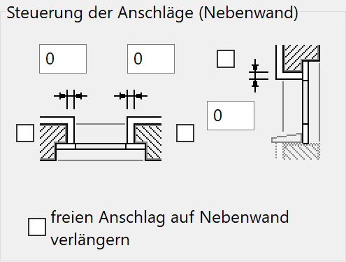
The option LENGTHEN FREE STOPS AT SIDE WALL means that the stop is tangentially extended to the side wall.
Stop
Left, right, top and bottom.
If the lintel stop is inactive, this is overridden by a roll blind setting.
Window combinations
In order for two individual windows to be closed together (e.g. window with window doors), the stop must be set to 0 for the combination and the tick removed in the check box below it (in the illustration for the stop on the right).
Define free stops
In order for free stops to be defined, the window must have been set previously with normal stops.
The free stops are drawn directly into the preview window.
Free stops are only defined for the wall layers, which differ from the automatic stop.
The window can be saved as a parameter.
Limitation: Free stops do not match modified window depths (in wall).
Procedure
Select the stop side with the display dropdown menu.
![]()
Set the contour in the preview window using the help lines.
![]()
Draw contour for layer in the preview window: From layer outer side (point 1) to layer inner side (point 2). Double-click to close. It can also be started from the layer inner side.

An individual contour must be drawn for each layer to be modified.


The parameters of this type of window can be passed on using the COPY PARAMETERS function.
![]()
The function DELETE FREE STOP removes a previously drawn stop. You need to click it with the mouse in the preview window.
Note
Windows with free stops can be saved as parameters.
Modify wall layer thicknesses and W-frame depth (in wall):
- Point 1 + 2 stay on the layer border.
- All elements of the contour maintain their original length, with the exception of the last element for point 2.
- If the contour only consists of one element (as in the first example), then this is dragged to the new length between point 1 + 2.
- It follows from this that: A change to the W-frame depth (in wall) requires a modification of the layer thickness and is only possible for simple contours (first example).
Tool for window division/muntins
![]()
The window editor can be launched using the button in the window parameter or from the property bar.
This tool allows you to set the window divisions manually. All window divisions, which are no longer possible with the WINDOW DIVISION or MUNTINS function, can be set using this function without any problems. The functionality is explained in the Glass element section.