Window
|
|
Construction parts toolbar |
| AR Objects menu > Create window |
Note
The window and the roof windows and flat roof windows are joined under this one function, but differ in principle in their setting options.
Create Window
When you click the CREATE WINDOW function, the settings are copied from the most recently placed window and the window can be placed immediately. The Position of window query appears in the entry line.
Window property bar

The property bar becomes visible as soon as the CREATE WINDOWS function is launched or if an existing window is edited.
You can manipulate the main values in the property bar.
| Function | Description |
|---|---|
| Window parameters | |
 |
Type |
| Renovation planning state | |
| Window shape | |
| Window width | |
| Window height | |
| Height of w-base | |
| Depth | |
| Niche | |
| Fill automatically(renovation planning) | |
| Lintel depiction | |
| Window height | |
| Entry from | |
| Division editor | |
| Stop type / Stop editor |
Window parameters
![]()
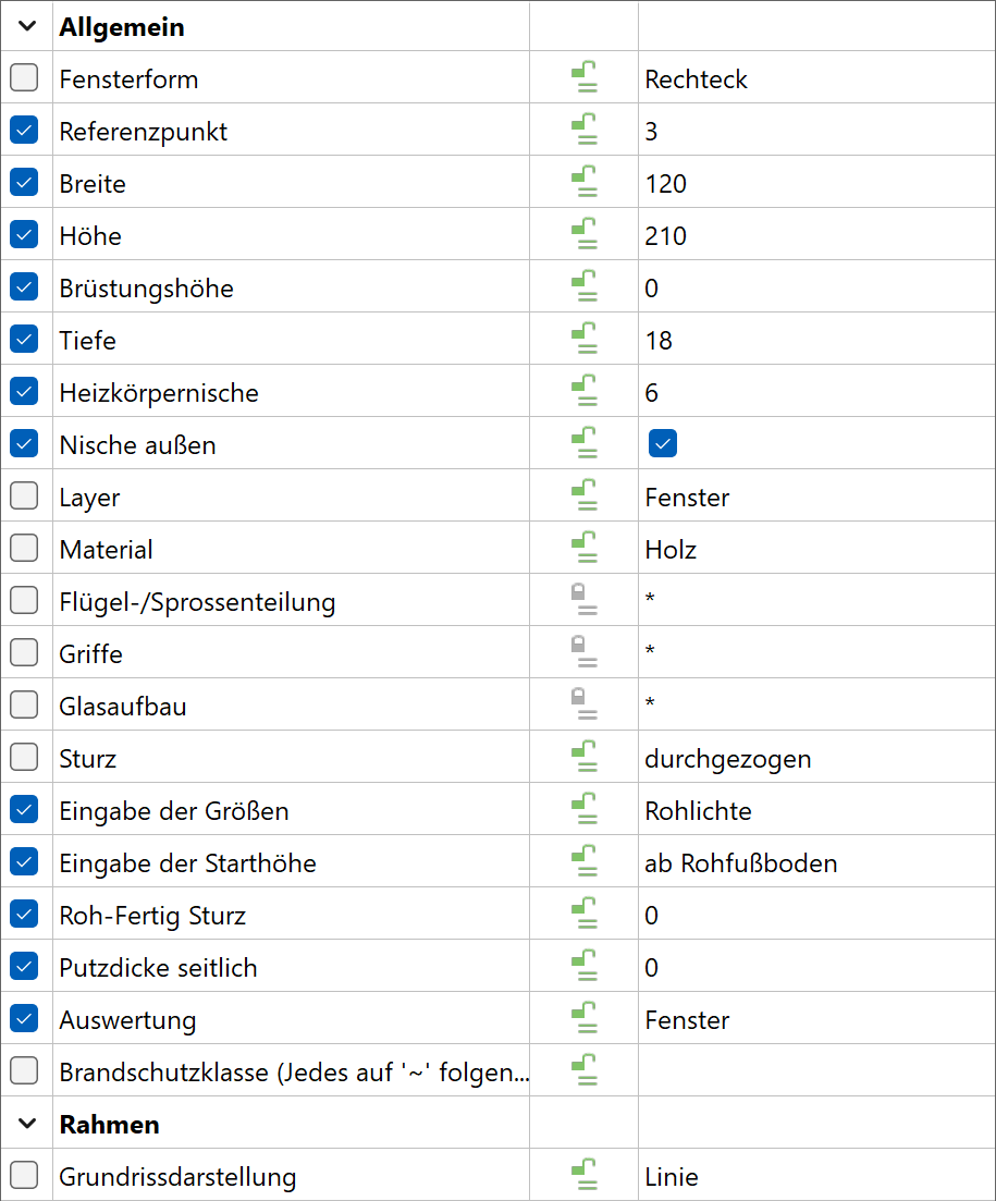
You can open the window parameters from the property bar or by double-clicking the window to be modified.

General parameters
 Status renovation planning
 Freeze
 Type
Type Layer
Layer
The general parameters for architectural objects are described in chapter Architecture objects.
Material
The material is taken into account in the report. Any name can be chosen from the dropdown or simply entered into and confirmed with Enter . If you want to remove a name from the dropdown list, enter it with a preceding minus sign and confirm with Enter .
Parameter management
The settings are saved in the config.val for architecture (see document for ELITECAD configuration).
A drawing with the name window_parametername.d is also saved in the same directory. The drawing for the most recently used current parameter with the name window_act_.d is also saved there.
All special settings such as free contours and free stops are also saved in the drawing.
Tip
The following procedure is recommended in order to limit the time required for assembling the parameter list:
Reduce saved parameters to the essentials.
Save windows with special settings with the corresponding wall construction in a separate overview drawing or library. If one of these windows is required later, it can be edited and saved as a parameter.
You can find a large number of window examples in the "Glass constructions" example object. This can be adopted as a parameter and saved.
Stop type
![]()
![]()
Overview
The settings in system control, region and language options influence the gross clearance/finished clearance window dimension entries.
For the country settings Switzerland and France, the outer sill is always measured from the top side.
In all other settings, the inner bare parapet top side is definitive for the gross clearance. For the finished clearance, the finished inner parapet top side (inner window sill) or exterior window sill can be selected.
Window without stop
![]()
![]()

Gross clearance and finished clearance. Difference due to plaster thickness and roll blinds.
Window with stop
![]()
![]()
 Gross clearance and finished clearance for a window without stop.
The thickness of the stop brick for the cavity wall is determined by the exterior wall layer as standard. This can be edited in the stop editor.
Window with external insulation (composite thermal insulation system) and back-ventilated facades
![]()
![]()

The gross clearance refers to the solid wall. The stop width and roll blind reduce the gross clearance to finished clearance.
As standard, the outer layers are drawn into the reveal without an air space. This reduces the total thickness of the layers to the stop width.

The gross clearance (wall aperture) can be selected for the opening dimension.
Walling
![]()
![]()

Walling clearance dimension.
Window with internal insulation
![]()
![]()

Copy parameters

Window dimensions
There are different entry fields available depending on the selected window shape. The numerical data with a grey background on the left of the field provides entry help. This is always the addition of the window height and parapet height depending on the remaining entries (e.g. from raw slab).
Entry
Gross clearance/finished clearance
There is a choice between the entry style gross clearance (wall clearance) and finished clearance for entering the window opening dimension clearance.
The difference depends on the stop type selected.
Tip
The window is displayed in 3D without side joints between the frame on the wall and the raw opening. When the joint is switched on, a 2D line is depicted in the plan graphics.
Parapet height entry method
The parapet height entry style only applies to how you enter your dimensions for the parapet, specifically whether you specify a raw dimension or a finished dimension.
Bare parapet height = raw storey floor top edge or level floor to bare parapet top edge without window sill.
Finished parapet height = top edge finished floor to top edge interior sill. For the France and Switzerland country setting, up to window sill top edge.
The (finished) floor height is defined for storeys in the structure settings. If a room name is set, the (finished) floor height assigned there takes precedence over the structure setting.
External reveal depth
![]()
Entry in the property bar (illustration) or in the window parameter.
Recess/recess for radiator
The width corresponds to the external frame dimension plus joints. Input in the window parameters.
Window doors: If the lower window frame is at floor height, a recess must always be set with the depth of the inner reveal.
Outside recess
If this option is activated, the floor/outer covering is drawn as a recess to the window frame as soon as the bottom edge of the frame lies lower than the top edge of the outer covering.
Report object as
The window can be quantified as a window or a door.
Opening in 3D

This setting is generally active. The setting to create an opening into the 3D wall may be deactivated. In that case, only a 2D depiction of a window is generated in the wall.
Fire protection
In addition to the labelling of the window, the fire protection class is added. Any symbol that follows the tilde "~" symbol, will be depicted subscripted. The tilde symbol itself is not depicted. The "fire protection" field is written into the project book for each report and is used in the window report.
2D only in active storey
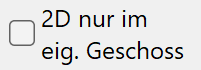
The 2D depiction for multi-storey windows can be either in the own storey or in other storeys.
Renovation planning – fill automatically

If the status of a door is changed to demolition, the automatic generation of a wall that fills the hole can be triggered with this option.
Copy parameters
Window shape
![]()
![]()
![]()
![]()
![]()
![]()
![]()
![]()
![]()
![]()
![]()
![]()
![]()
![]()
There are 14 different shape types available for selection. The first 12 of these shapes are standard shapes, which have clearly defined outer contours (shape of the window reveal).
Workshop
Corner window Work plane is on the normal storey work plane.
- CREATE WINDOW function.

- Select corner window shape.

- As an additional value for corner windows, the window frame widening of the corner frame (left) and the window frame width for the corner frame (right) can be set. The window frame width = 0 setting transfers the window frame width from the frame detail parameter.

- Place the window by entering both corner points and the direction of the corner window.


- In order to define a frameless corner window it is necessary to deactivate the corner column. Additionally, the frame width at the corner has to be set to 0. In such cases, the corner element may not be defined as a window that can be opened.

The window by free form shape allows you to define a free window contour. This contour should lie "on the wall" i.e. the work plane is positioned on the wall surface and a closed polygon is drawn there. Note here that windows of this shape are generally installed from the outer side of the wall. Various options (roll blind, window sill, walling, etc.) are not available for this shape
Workshop
window by free form Place your work plane on the building outer shell (so that the window opens inwards). There are various ways to do this, e.g. by switching on the solid view Ctrl + D , opening the WORK PLANE ON SURFACE function and selecting the wall view.
 |
 |
Draw a closed polygon as an exterior window contour. All of the drawing functions and help geometry are available here.
Run the WINDOW function to convert to a window. Select the WINDOW BY FREE FORM window shape and assign this to the drawn contour.
![]()
The window by free rectangle shape is a simple tool for entering rectangular windows in 3D. Position the work plane on the wall. When opening the WINDOW function, only the bottom left and top right corner of the opening are queried. All further depiction variants result from the parameters set.
Workshop
Window over multiple storeys
A window over multiple storeys can normally be set in the floor plan in the lowest involved storey. The correct height can be directly entered for the window height. The window is created throughout all storeys with one floor plan per storey. The wall axes must be exactly over each other.
You can also proceed in the same way as the WINDOW BY FREE FORM function (previous workshop) and place the work plane on the wall.
Drag the window to the facade with the WINDOW BY FREE RECTANGLE function. Left lower corner, then right upper corner.
Copy parameters
