Create Axis-Grid
|
|
AR Objects toolbar |
| AR Objects menu > Axis-grid |
The axis grid consists of two orthogonal axes, the horizontal X-axis and the vertical Y-axis. For rotated axis systems, you must create the grid on a rotated coordinate system: See DEFINE COORDINATE SYSTEM function.
Axis grid property bar

The property bar is visible as soon as the function CREATE AXIS GRID is started or an existing axis grid is edited. The property bar is used to modify the main properties of an axis grid.
| Function | Description |
|---|---|
| Axis grid parameters | |
 |
Type |
| Renovation planning state | |
| Number of grid lines along X- or Y-axis | |
| Distance between two grid lines | |
| Grid line start offset | |
| Grid line pen | |
| Grid line type |
Axis grid parameters
![]()
You can open the axis-grid parameters window from the property bar or by double-clicking the axis-grid to be modified.
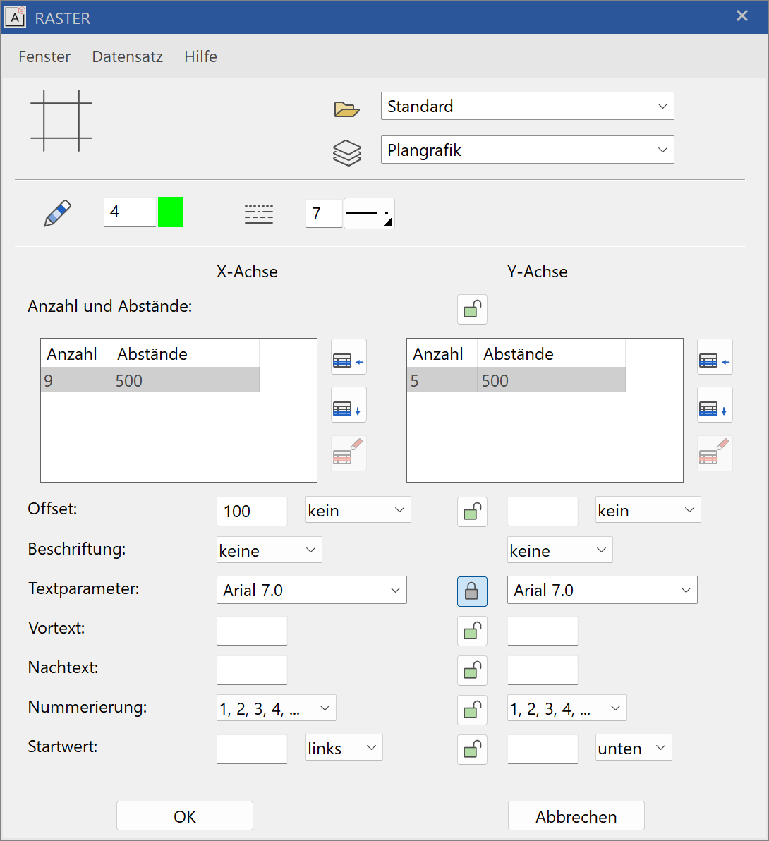
General parameters
 Renovation planning state (only in ELITECAD Architecture)
 Freeze (only in ELITECAD Architecture)
 Type
Type Layer
Layer
The general parameters for architectural objects are described in chapter Architecture objects.
Pen/line type

Pen- and line type of grid lines.
Geometry
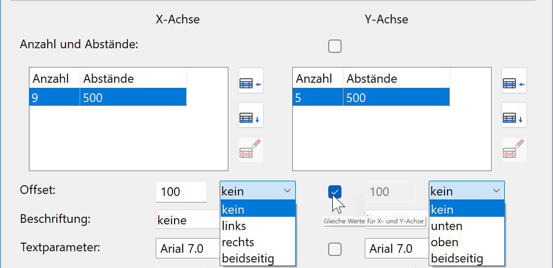
The settings are subdivided into one column for the X-axis and one column for the Y-axis. If the Y-axis is the same as the X-axis, you can check the "Same" option in the middle column.
Improved · 16 R1 · Improvements
In the two tables, specify the number of grid lines in the X- and Y-direction along with their spacing.
![]() Insert line
Insert line
![]() Append line
Append line
![]() Delete line
Delete line
The offset defines the overlap of the axes over the axis section points along the edges of the grid surface. The offset can be on one or both sides.
Label
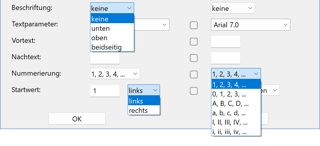
The axes can be labelled on one or both sides. The text is controlled by a predefined text parameter. There are various formats available for the numbering. You can specify the start value of the numbering as well as whether the numbering should rise from left to right or from right to left.
Create facade-grid
|
|
AR Objects toolbar |
| AR Objects menu > Facade grid |
The facade grid copies the heights from the structure settings and can be placed on a building's outer facade.
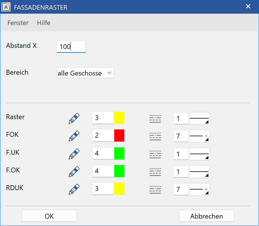
The recommended value for the X-spacing (grid) is adopted from the structure settings dimension system. The spacing values of all height lines come from the values in the structure settings and only their pen and line type can be modified in this window.
- FFL = Finished Floor Level
- W.PAR = Window Parapet Height
- W.LI = Window Lintel Height
- LFS = Lower Floor Surface
Workshop
Create facade grid
Before executing this function, place your work plane on a facade exterior surface.
Open the CREATE FACADE GRID parameters window, enter the desired values and confirm by clicking  . You will be prompted for the lower left and upper right positions of the axis grid.
![]()
![]()

After the facade grid has been placed, you can open up the space for the windows on the same work plane. All windows are automatically assigned to their associated storey, even if that storey is not the active one at the time of installation.
![]()
![]()
