Stair Parameters
![]()
The first time you call up the parameter window, it is populated with pre-set values. When it is called up subsequently, the most recently specified values are retained (provided the parameter window was closed by clicking  ).
).
Stair parameter window

| Stair types | |
|---|---|
| Straight flight | |
| Straight flight with intermediate landing | |
| Quarter turn stair with intermediate landing | |
| Dogleg stair with intermediate landing | |
| Spiral stair | |
| Quarter turn staircase | |
| Full dogleg winding staircase | |
| Dogleg winding stair | |
| Free form stair | |
| Modular stair |
In practice, you can use these stair types to generate most necessary stairs. If any other stair shapes are necessary, you can usually generate them out of a combination of the pre-set stair types or using the various 3D functions.
General parameters
 Renovation planning state (only in ELITECAD Architecture)
 Freeze (only in ELITECAD Architecture)
 Type
Type Layer
Layer
The general parameters for architectural objects are described in chapter Architecture objects.
Main tabs
![]() Stair geometry (always open)
Stair geometry (always open)
![]() Landing and step winding (greyed if stair shape has no landing)
Landing and step winding (greyed if stair shape has no landing)
![]() Step lay out
Step lay out
![]() Bearing construction
Bearing construction
![]() Stringer
Stringer
![]() Stair endings (greyed for Spiral stair)
Stair endings (greyed for Spiral stair)
![]() Plan graphics
Plan graphics
General information about the stair parameters
The appearance of the parameter window and the types of configurable values vary depending on the stair shape.
![]() Entrance/exit
Entrance/exit
![]() Rotational direction
Rotational direction
![]() Height definition
Height definition
![]() Limitation values
Limitation values
The stair dialog has "calculation fields". These are greyed-out values and the results of calculations based on other configured values.
For example, changing the suggested rise naturally also leads to changing the run length of the stair. Likewise, changing the number of steps results in adjusting the slope measurement.
To generate the stair in ELITECAD Architecture, select the storey on which the stair should stand from the storey list. This is also, where the plan graphics is generated. Keep in mind that the program always considers the value provided for the entrance level to be relative to the storey level. In ELITECAD Mechanics, the stair is placed on the active work plane.
The entry for placing the stair is already active once the parameter window has been opened.
You cannot close the parameter window with until the stair has been placed.
You cannot make additional modifications from the parameter window until you have confirmed with
 .
.
If you modify the stair (by double-clicking), the parameter window with the respective settings opens.
Stair geometry
![]()
The parameter window displays graphics and entry values for the stair geometry depending on the stair shape. Based on the shape, the geometry distinguishes between "straight" stairs, stairs "with intermediate landing" and "spiral" stairs.
Floor plan geometry
The graphics and entry fields vary depending on the stair shape.
| Example: |
|---|
 |
| Quarter turn staircase |
![]() Lock
Lock
Activating a value's "lock buttons" blocks that value from affecting the geometry calculations. If you change the tread width, the locked values for the stair length are not recalculated.
If both length values are locked and you change the tread width, the number of steps is automatically corrected.
| Example: |
|---|
 |
| Dogleg stair with intermediate landing |
![]() Lock
Lock
If one of the "lock buttons" is selected for a dogleg stair with intermediate landing, the value is only fixed if "Free offset" is set under the Landing options. For all other LANDING options, stair length is automatically calculated. If both stair lengths are fixed, this is automatically adjusted.
In the absence of fixed values, the system attempts to include as many steps as possible with the shortest possible stride length in a flight.
A stringer length can be shortened or lengthened by increasing or decreasing the step number of the lower section or upper section. You can also adjust the stringer length by adjusting the step offset on the landing.
![]()
![]() Change exit and entrance
Change exit and entrance
![]()
![]() Change rotational direction of stairs
Change rotational direction of stairs
You can use these functions to change the position after the stair has been placed while modifying it.
Start height and number of steps
When you open the parameter window in ELITECAD Architecture, the storey height of the current storey is adopted as the "start height". The number of steps is based on the maximum rise of step.
| Examples: | |
|---|---|
 |
 |
| Quarter turn staircase | Dogleg stair with intermediate landing |
There are three options available from the height definition:
![]() Free height and entrance level
Free height and entrance level
![]() Free height from storey level
Free height from storey level
![]() Storey height from storey level
Storey height from storey level
![]() Free entrance level to Storey height
Free entrance level to Storey height
For storey height, the rise height is determined from the entries in the storey list. Likewise, the thickness of slabs and floor compositions are automatically adopted and thus cannot be modified directly.
In order to enter a custom entrance height, you can unlock the height value, enter a new value, and re-lock it. The number of steps is automatically calculated or can be configured manually if "Optimizing" is switched off for the limitation values.
When the "Maintain step sum" button is pressed for stairs with an intermediate landing, changing the stringer lengths does not increase the number of steps, but only shifts them between the step number for the lower section and upper section.
If you unlock this, changing the string lengths calculates a new number of steps for the respective flight.
![]() Retain number of steps
Retain number of steps
Slope ratio
The "rise of step" is given from the rise and the number of steps. The "tread width" (J) is calculated using the formula 2*I+J = 63, for which you should configure the possible lower and upper value for the "step length" under Parameter limitation values.
You can change the "tread width" manually within these limitation values. That automatically changes the stringer lengths.
If the stair's "rise" is not fixed, you can also enter the "rise of step" (I), and the rise will be calculated from the stringer lengths and the number of steps.

Parameter limitation values
![]()
In this dialog window, you can define the upper and lower limitation values for the "stride length", within which you can adjust the "rise of step" or "tread width". You should also configure the "maximum rise" and the "minimum tread width" for winding with spiral staircases.
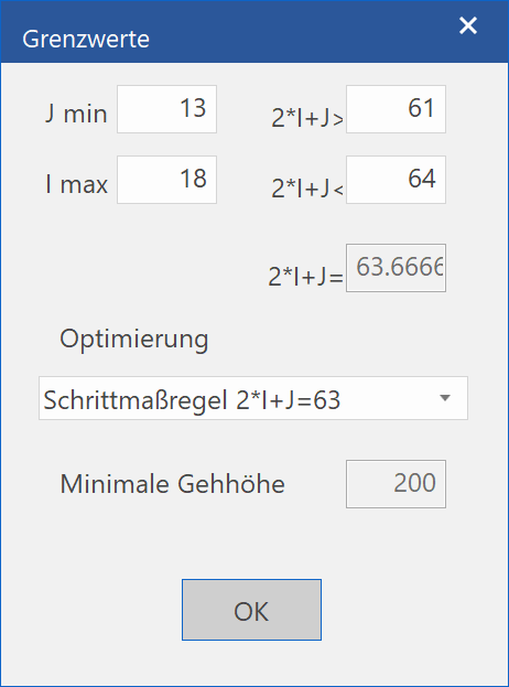
J min: Minimal tread width when winding
I min: Maximum rise
2*I+J> Bottom limit for tread depth
2*I+J< Upper limit for tread depth
2*I+J= Active tread depth
For "Optimizing", you can select between "No optimizing", the "Step formula", or the "Security rule".
Finally, you can define the "Minimal head room".
Tip
To create a stair that does not always recalculate when a value is modified, you can switch "Optimizing" to "No optimizing". Despite this, you will still recognise if the limitation values are exceeded, as the fields will be highlighted in red.

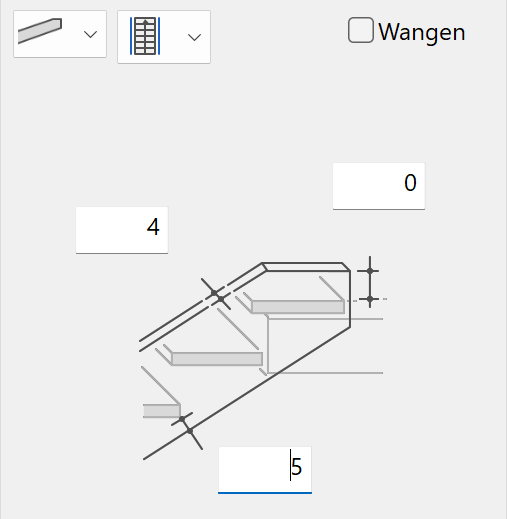
Landing design
![]()
For "intermediate landings", you can specify the offset of the entrance and exit to the landing edge as well as the landing base thickness.

The landing base thickness is fixed in three cases by the assumption that the sectioning edge (bending line) is continuous for a dogleg stair and flush with the stair width for an angled stair.
Free alignment
![]()
You can specify any alignment via the front step edges and the sectioning edges of the lower edge of the tread. The bending line is based on the landing base thickness.
Shift the lower section by one step
![]()
The front step edge for the lower flight is offset one step width from the landing. The landing base thickness is calculated (narrowest landing base thickness).
Shift the lower and upper sections by a half step
![]()
The front step edges for both flights are shifted by a half step width from the landing. The landing base thickness is calculated.
Shift the upper section by one step
![]()
The front step edge for the upper flight is offset one step width from the landing. The landing base thickness is calculated (largest landing base thickness).
Changing the "offset" also simultaneously changes the stringer lengths in the floor plan and vice versa.
To achieve a specific alignment (e.g. half a step), you can first lock the alignment and then define the landing base thickness accordingly using "Free offset". The offset of the bending lines is calculated from the landing base thickness.
When entering as a "Free offset", the bending line of the tread underside is not bound to the landing edge, but may also extend into the landing for the lower flight.
An automatic material hatch is not currently implemented for the section depiction.
Tip
You cannot specify the shape of the landing using this function. However, you can define the shape either in the floor plan depiction or in 3D using standard 2D functions.
Step winding
![]()
For spiral staircases, position both the "stair path" as well as the "corner radius" of the inside stringer.
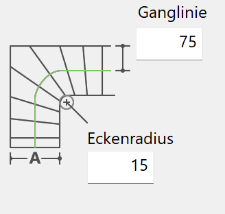
When the stair is generated, the winding is automatically configured based on the lowest number of steps for entrance or exit. The winding is built up symmetrically starting from the corner step (minimum "tread width").
The smallest "tread width" is based off of the limitation value (J min).
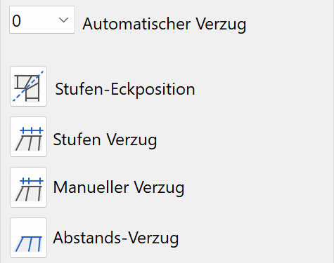
Automatic winding

The number of steps can be changed accordingly. If you select a number of steps that is too low (below the minimum "tread width"), the system calculates the closest possible number of steps that satisfies the conditions. If you enter the value "0", all steps are realigned to be "normal to the stair path".
Step-corner position
![]()
You can use this function to draw a reference line representing either the edge or the middle of the steps. The position of the stair path is automatically corrected.
| Example: | |
|---|---|
 |
 |
| Specify first and second point | 1 for middle of step |
Tip
For a quarter-turn stair, you must complete the function after the first line with Enter .
Step winding
![]()
Enter offset area via the first and last step. The "tread width" is retained on the stair path.
Manual winding setting
![]()
You can wind each individual step based on its position on the inside or outside stringer.
There is also an option to unlock the stair path. Once the function is activated, the value can be entered in the entry line. Entering "0" removes the lock. Entering "1" keeps the rotation point for winding on the stair path.
Distance winding
![]()
You can wind individual steps based on the distance to the previous step.
There is also an option to switch off unlock the stair path. Once the function is activated, the value can be entered in the entry line. Entering "0" removes the lock. Entering "1" keeps the rotation point for winding on the stair path.
Tip
You can combine stair winding with any other options if automatic winding is switched off.
When the subsequent warning appears, you must first set "automatic winding" to "0".
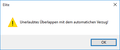
The step winding is constructed on the inside stringer following the projection method. With "automatic winding", the range of winding is adopted symmetrical to the wedge-shaped step (corner step).

Step lay out
![]()
There are two designs available: one with a "nosing over step riser" and another with an "angled riser". These layouts are also displayed in 3D. In the 2D graphics, the front step edge and the raw edge are displayed. If you change the "nosing" of the tread or angled riser or the " thickness of the step riser", the position of the front step edges remains locked and the construction is shifted towards the stair path.
| Example: | |
|---|---|
 |
 |
| With nosing over step riser | with angled riser |
The third option is for all dimensions to relate to the raw stair. This can be used for a prefabricated stair, for example.
Material and its linkage
![]()
![]()
This setting is only available in ELITECAD Architecture.
The settings for a stair's pen and hatch can be stored together under one name. This "material name" is managed within the representation levels. The material settings are specific to the representation level; in other words, they are different depending on which representation level is active. For more information, please refer to the Representation levels chapter.
Pen and hatching parameters
![]()
![]()
If the material is linked with the parameter record, you cannot change the configured pen or the hatch name. If you undo the link (by "unlocking" the lock icon), you can configure the pen and hatch using the combo box or selection list. However, that does not change the material's stored settings. These can only be changed within representation level management.
![]()
![]()
This switch allows you to toggle between colour mode and material mode. For more details, see the Colours and Materials chapters.
Bearing construction
![]()
You can select one of three different designs for the bearing construction. Currently, you can only use the beam for straight flights of stairs.
![]() Centred beam
Centred beam
![]() 2 symmetric beam
2 symmetric beam
![]() Tread (full stair width)
Tread (full stair width)
| Examples: | |
|---|---|
 |
 |
| tread | 2 symmetric beams |
Tip
For the tread, you can also choose between a straight and an offset bottom view.
Material and its linkage
![]()
![]()
This setting is only available in ELITECAD Architecture.
The settings for a stair's pen and hatch can be stored together under one name. This "material name" is managed within the representation levels. The material settings are specific to the representation level; in other words, they are different depending on which representation level is active. For more information, please refer to the Representation levels chapter.
Pen and hatching parameters
![]()
![]()
If the material is linked with the parameter record, you cannot change the configured pen or the hatch name. If you undo the link (by "unlocking" the lock icon), you can configure the pen and hatch using the combo box or selection list. However, that does not change the material's stored settings. These can only be changed within representation level management.
![]()
![]()
This switch allows you to toggle between colour mode and material mode. For more details, see the Colours and Materials chapters.
Tip
You can switch off the depiction of the tread. This may be useful if you want to represent a stringer stair, for instance.
Stringer
![]()
Here, you can enter three values for the stringer: the bottom height, upper height and stringer thickness.
Side
Improved · 16 R1 · Improvements
![]()
![]()
![]()
Stringers can be created either on the left, on the right or on both sides.
Execution
![]()
![]()
A free cross-sectional contour can be selected for the variable design.
Material and its linkage
![]()
![]()
This setting is only available in ELITECAD Architecture.
The settings for a stair's pen and hatch can be stored together under one name. This "material name" is managed within the representation levels. The material settings are specific to the representation level; in other words, they are different depending on which representation level is active. For more information, please refer to the Representation levels chapter.
Pen and hatching parameters
![]()
![]()
If the material is linked with the parameter record, you cannot change the configured pen or the hatch name. If you undo the link (by "unlocking" the lock icon), you can configure the pen and hatch using the combo box or selection list. However, that does not change the material's stored settings. These can only be changed within representation level management.
![]()
![]()
This switch allows you to toggle between colour mode and material mode. For more details, see the Colours and Materials chapters.
Stair endings
Stair foot
![]()
You can select among five options for the design of the stair foot.
![]() Horizontal support (for slab or foundation)
Horizontal support (for slab or foundation)
![]() Partly vertical connection
Partly vertical connection
![]() Fully vertical connection
Fully vertical connection
![]() Vertical connection to lower tread
Vertical connection to lower tread
![]() With protruding nosing
With protruding nosing
| Example: |
|---|
 |
| With protruding nosing |
The values on the parameter window refer to the design of the connection to the tread.
The A and B values lock each other. In other words, if the B value is locked (B button), its value is preserved when changing the tread thickness and the A value is adjusted accordingly.
Similarly, you can use D and E to determine the height of the bracket, and can also lock them when modifying the gross ceiling thickness or the floor composition.
The support width is defined by the C value.
If the height indication was set at storey height in ELITECAD Architecture, the gross ceiling and slab gauges are set in the Storey manager and cannot be changed.
Stair head
![]()
There are three options available for the design of the stair head.
![]() Vertical termination
Vertical termination
![]() Horizontal termination
Horizontal termination
![]() With protruding nosing
With protruding nosing
| Example: |
|---|
 |
| with vertical termination |
The A and B values lock each other. In other words, if the B value is locked, its value is preserved when changing the tread thickness and the A value is adjusted accordingly.
If the height indication was set at storey height in ELITECAD Architecture, the gross ceiling and slab gauges are set in the Storey manager and cannot be changed.
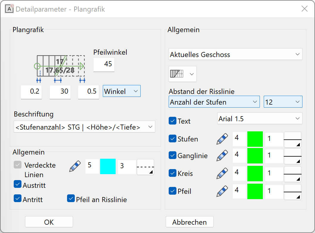
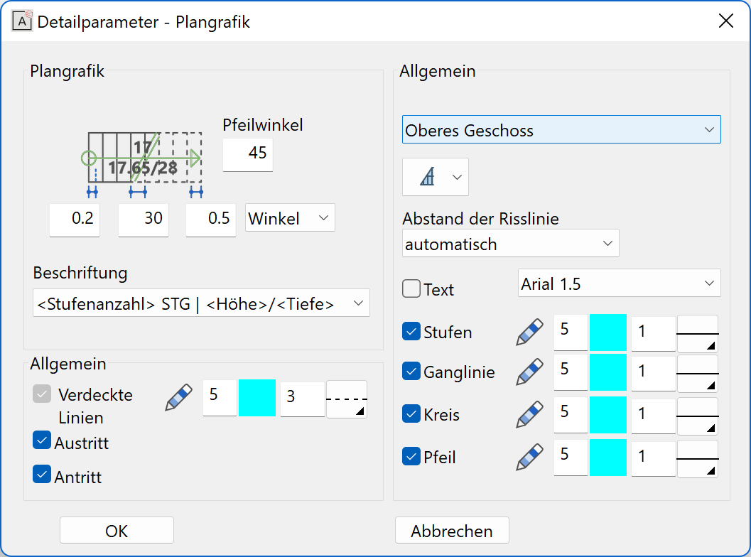
Plan graphics
![]()
The floor plan depiction contains both the stair flights as well as the landing contour.
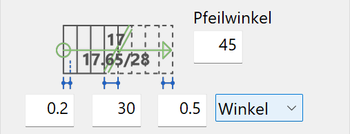
The factors for circle radius and arrow length are based on the "tread width". For the section line, you can select either factor or angle.
The type of text can be selected from the "selection box" where all records saved under the text parameters are listed.
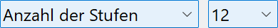
In ELITECAD Architecture, there are four different types of depiction on the lower storey and two types for the upper story. In ELITECAD Mechanics, there are no options available.
 |
 |
 |
 |
 |
 |
You can determine the position of the section line automatically or manually.
 |
 |
|---|---|
 |
 |
You can also separately configure or switch off the pen/line type for steps, the section and stair path, the circle at the entrance and the arrow at the exit. Later you can specify whether the exit should be depicted in 2D.
Edit stair
Stairs can be edited and modified at any time by double-clicking them. All detail settings can be modified at a later point. It is also possible to modify the stair type, except with a free form or modular stair.
In ELITECAD Architecture, you can use COPY INTO ACTIVE STOREY to adopt stairs into a storey, automatically adapting the "rise".