Wall Property Bar

The property bar is visible as soon as the CREATE WALL function is started or if an existing wall is edited.
You can manipulate the main values in the wall's property bar.


Wall parameters
![]()
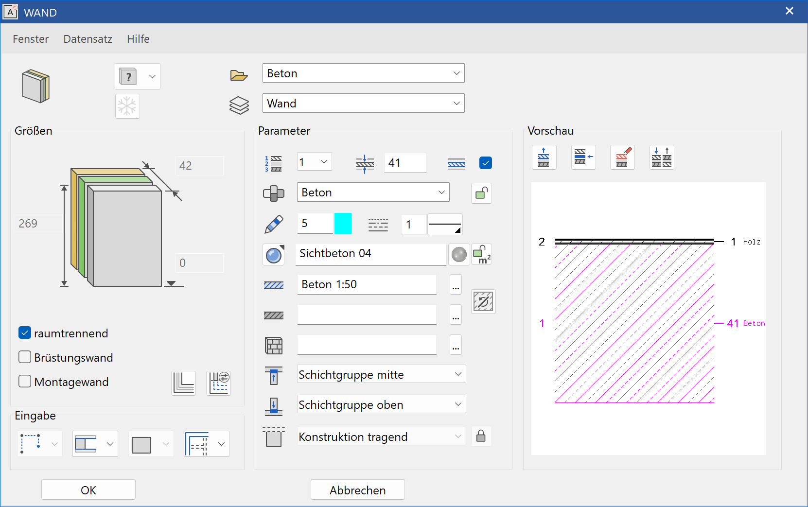
You can open the wall parameters window from the property bar or by double-clicking the wall to be modified. The parameters window has three columns. First, the General Settings including the dimensions and entry method, then the settings of each layer and finally the layer preview.
General parameters
 Renovation planning state
 Freeze
 Type
Type Layer
Layer
The general parameters for architectural objects are described in chapter Architecture objects.
Dimensions
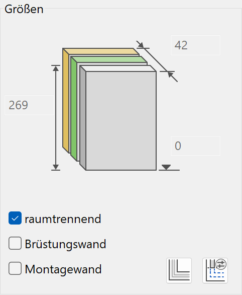
Depending on the selected height reference, you can configure the bottom edge and height values freely.
Room-dividing
This property should always be selected by default. Non–room-dividing walls would include toilet stall walls, dormer walls, facing panels and the like. If a wall is room-dividing, it divides surfaces when calculating room area.
Parapet wall
If a wall is labelled a parapet wall, the hatch is automatically hidden in the floor plan and the settings are used in the "Roof section/secondary wall detail parameter" for the floor plan depiction. The hatch is preserved in the section.
Binding beam
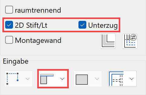
If "Wall to ceiling" or "Free wall reference" is selected for the height reference, the BINDING BEAM option also appears. When this option is selected, the wall is reported as a binding beam. The 2D PEN/LT option corresponds to a parapet wall.
System-built wall
When this option is selected, the wall is reported as a whole and not by layers.
Main wall
This option only appears if multiple walls are linked with each other. If a construction is labelled the "Main wall", it is the one depicted in the floor plan as the cross section. If a wall is a "Secondary wall", the cross section does not appear and the depiction follows the settings under "Roof section/secondary wall detail parameter".
View with envelope
![]()
For multi-layered walls, the depiction in views can be set to show the envelope only.
Roof section/secondary wall detail parameter
![]()
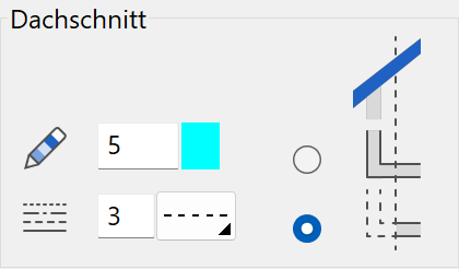
Here, you can configure the pen and line type for the areas that are not visible for a roof section. However, you can also switch off depiction.
| Switched on | Switched off |
|---|---|
 |
 |
 |
 |
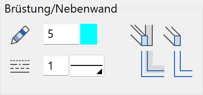
Here, you can configure the pen and line type for the floor plan, if the parapet wall, 2D pen/lt or secondary wall options are selected.
Entry
Entry mode
Draw contour manually
![]()
Entry is via the wall axis. This is a freely definable polygon or rectangle. If at the end the polygon leads back to its start, the wall is drawn immediately. In all other cases, the wall polygon is closed by clicking the endpoint twice.
For the query Which direction?, you can define the wall's direction, i.e. the position of the wall axis. The options are the centre, the right side of the wall or the left side of the wall. This axis is adopted as the reference line for later changes to the wall thickness.
Create wall from existing contour
![]()
First, you must draw a contour that follows the desired wall path. Always place this contour on the storey level, even if the wall is to relate to a shifted level floor. After defining the contour, you must define the position of the axis (wall direction) with the cursor.
Define wall from outline
![]()
The first two entry options are used to draw the wall axis. This always results in a uniformly thick wall. With this option, the entire outline of the wall is drawn as a closed polygon. This makes it possible to create tapered walls as well. This entry mode is only available for single-layered walls.
Examples:


Height reference
Choosing the correct height reference simplifies entry and has advantages for later modifications to the structure settings.
Walls that use a slab as a reference automatically adjust themselves if the slab is modified (height reference of slab: Storey slab or level floor). A free wall never auto-adjusts.
Height reference – Wall from floor to ceiling (standard)
![]()
You can save the effort of entering heights, as this wall is always located between the storey slabs of two storeys. The slabs must have Storey slab or level floor as their height references to be accounted for by the walls. This is the typical setting for interior walls.
If the wall has a roof over it (that belongs to the same storey and the same structure), the storey wall connects automatically.
Height reference – Wall – underside floor to ceiling
![]()
The wall begins at the underside of the floor and goes up to the underside of the ceiling. This reference is used for the exterior wall in order to create a closed outer shell.
Height reference - Wall to ceiling
![]()
This wall is oriented with its upper edge on the next ceiling slab or a roof within the same storey. The underside is connected to the raw slab.
Note
If you also select the BINDING BEAM option for this wall reference, the wall is reported as a binding beam.

Height reference - Wall from floor
![]()
Wall from floor is for a parapet wall standing on a floor. References a Storey slab or level floor. The height can be freely configured and references the top edge of the slab. Roofs or storey slabs of higher storeys are not accounted for.
Height reference - Wall from floor underside
![]()
The wall from the floor underside starts at the lower edge of the storey slab and is defined with any height starting at that marker. The wall does not account for level floors.
Height reference - Wall up to roof with max. height
![]()
The wall has a maximum height and accounts for storey slab or level floors. The lower edge and height can be configured. This height reference has two usage areas:
The first usage is for a wall on the top floor that should adjust to fit the roof but only up to a specific wall height.

The other usage is for exterior walls, which have wall layers that are not clamped between the slabs and have other heights.
 |
 |
Height reference - Dormer walls
![]()
Wall between two roofs. After you specify the axis and direction of the wall, both roofs are queried for the limitation. The wall remains associated with both roofs.
Height reference - Free wall reference
Free walls do not reference floors or roofs.
Once the free wall is selected, you can also define the wall's shape in the adjacent dropdown selection box (only available for this wall type). The free wall entry is always defined by a combination of two fields. Depending on the selected shape, you are prompted to provide different details.
Below and above straight
![]()
![]()
For the straight shape, specifying the lower edge in reference to the ground floor (TS slab) and the wall height clearly defines the position of the wall in the storey.
Slanted below
![]()
![]()
This shape is well suited to defining dormer walls. The top edge of the wall is determined based on the specified height and the value for the lower edge (which only applies as a reference for the height dimension). You can either determine the lower section using a previously drawn 3D surface/box (e.g. a roof surface) or by entering the height of three free points. If you select the entry by points, simply imagine you are defining a plane in 3D space using the points. This "plane" slices off the bottom of the wall.
Slanted above
![]()
![]()
The SLANTED ABOVE shape functions similarly to the previous SLANTED BELOW function, except the top edge is the slanted one. This wall works well for firewalls that run above roofs, free facades, dormer walls or furrowed roofs.
Slanted below and above
![]()
![]()
The SLANTED ABOVE AND BELOW shape combines the two aforementioned wall shapes.
Define wall from lateral contour
![]()
![]()
The wall shape with a lateral contour is generated from the definition of a view. Draw the wall view as a closed polygon on the work plane in which the wall should be positioned (wall plane). After you launch the WALL function, the path of the wall is drawn. Finally, you must provide your drawn contour of the side view.
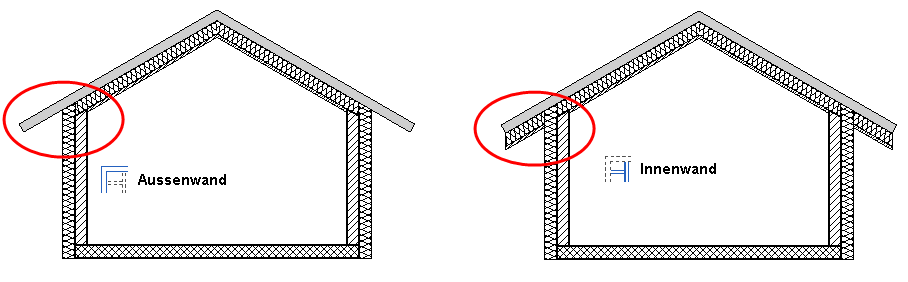
Outer wall/inner wall
It is relevant for the sections with floors and roofs whether a wall is inside or outside. If the outer walls form a closed contour, the layer groups sectioned by the outer wall are no longer displayed in the area in front of the roof.
Assign the correct surface area according to OE standard 1800 (2011) and EN 15221-6 in the reporting lists.
Outer wall
![]()
Inner wall
![]()
Partition wall
![]()
E.g. Dividing walls for office buildings
Flexible partition wall
![]()
E.g. Basement compartment or toilet stall dividing wall
Floor is created up to the wall axis.
Parameter
The parameter section displays the settings of the active wall layer.
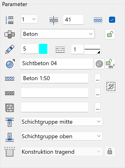
Number of active layer
![]()
For multi-layered walls, you can select the desired layer in order to configure its settings. Instead of selecting the number, you can click directly on the layer in the preview.
Thickness of active layer
![]()
Main layer/supplementary layer

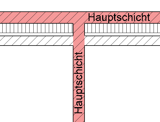
If a wall layer is defined as the main layer, it automatically intersects other main layers.
Material and its linkage
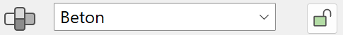
The materials and their corresponding settings are saved in the representation level. When linkage to the representation level is selected (recommended), the pen and hatch settings are adopted and cannot be manipulated ("greyed out").
Pen and hatching parameters
![]()

When the linkage of the material is active, only the line type can be modified.
![]()
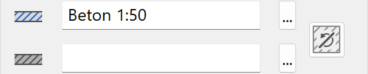
If you unlink the materials, the pen type and hatches can be modified. The settings are described in chapter Representation level > Materials management.
Colour mode/material mode


This switch allows you to toggle between colour mode and material mode. If a texture is defined, it takes precedence. The 3D colour appears for the empty texture field. For more details, see the Colours and Materials chapters.
Material for room label
If the lock is not set (open lock), the material configured in the room parameters takes precedence over the wall material. If the lock is set (lock closed), the material of the wall is displayed and not that of the wall label. Reporting does not account for these settings and uses the "material for room label" for the entire room.
 |
 |
3D hatch

The wall can be assigned a line hatch that appears in the calculated hidden line views.

Wall limitation top/bottom
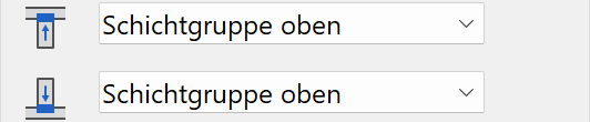
If the wall layer affects a slab or a roof, the sectioning settings take effect. They define which layer group the wall layer should lead up to. This can be specified for the upper and lower wall connection.
Layer type
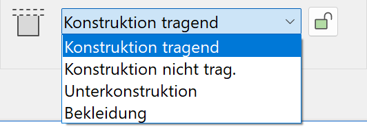
For the reporting to be correct, a layer type must be assigned to the layer.
If the linkage to the material is detached, you can make the assignment independently. If the linkage is active, the layer type is read from the reporting database using the material name.
Preview
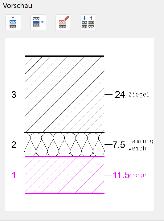
The current construction is displayed in the preview. Layers can be added, deleted or replaced. The wall axis is on wall layer labelled as #1. If you click on a layer in the preview, its parameters are displayed.
Add layer
![]()
This function adds a new layer to the last layer. This layer has the same settings as the current layer.
Insert layer
![]()
This function adds a new layer above the active layer.
Delete layer
![]()
Deletes the active layer.
Mirror layers
![]()
This function rotates the group of layers by 180 degrees.