DXF/DWG – Export
|
|
Interfaces toolbar |
| File menu > Export > DXF/DWG |
Main settings
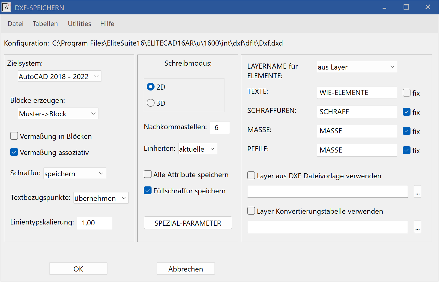
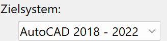
The desired AutoCAD/DXF-Version needs to be entered here. The generated data can be adjusted to the specified DXF-Version.
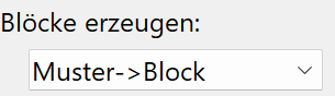
Model > Block: Every model becomes a block; the model name becomes a block name.
Level > Block: Every level becomes a block; the level name is applied.
Class >Block: Every class becomes a block; the class name is applied.
none: No blocks are generated. (Exception: dimension blocks)
ON: The dimensioning (dimension blocks) is entered into the model blocks. (Rather uncommon in DXF)
OFF: The dimensioning blocks are generated as separate blocks.
ON: DXF dimensions (DIMENSION) are generated.
OFF: Blocks with geometry and text are generated.
Special case: If the target system is set to easy geometry and the check box NO for generate blocks is selected, then no blocks will be generated for the dimensions. This setting is best for data transfer to CAD systems having problems with blocks.
do not save: Line hatches will not be saved.
save: Line hatches will be saved for up to AutoCAD13. (Attention: Files can become very large.) From AutoCAD14, hatches will be saved as associative hatches.
as block: The line hatches are saved as blocks.
adopt: The ELITECAD reference points (1-9) are adopted in DXF.
adjusted: The text is adjusted between two points. In other words, the overall text spacing always stays the same. For this reason, changes made to the text length always affect the text parameters.
aligned: The text parameters always remain the same regardless of the text length. In other words, if text becomes longer due to changes made, it will also need more space.
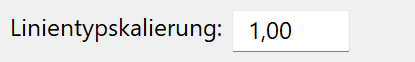
The scaling factor of the line types can be defined here.
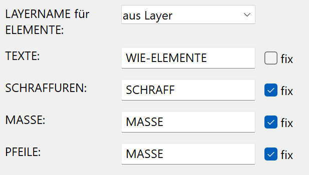
LAYER NAME for ELEMENTS:
from Group: The layer name is read from the classification GROUP.
from Class: The layer name is read from the classification CLASS.
from Level: The layer name is read from the classification LEVEL.
from Layer: The layer name is read from the layer attribute.
LAYER NAME for TEXTS / HATCHES / DIMENSIONS / ARROWS
fix OFF: Layer names for texts such as elements from the layer or attribute are read.
fix ON: The content of the text fields is used for the layer names.
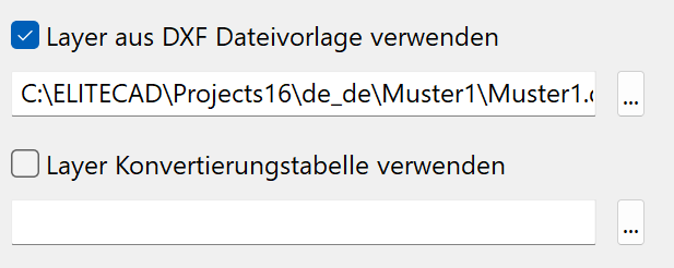
The USE LAYER FROM DXF FILE TEMPLATE option can be used in order to add an additional layer from the template to the DWG file.
If the USE LAYER FROM DXF FILE TEMPLATE option is activated, the properties "Colour from layer", "Line type from layer" and "Line thickness from layer" are additionally added to a DWG file.
ON: A selected DXF file is used as a template for the conversion.
OFF: The properties of the individual object are transferred.
An example of a DXF layer template:
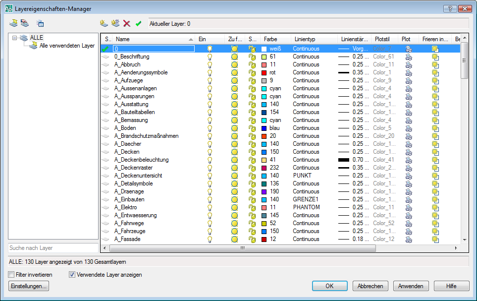
Explanation
In AutoCAD, colours, line types and line thickness are often governed by the layer property manager and not by the object itself. If these layer properties are desired by the recipient, this option can be used here.
The same layers must be defined as such in ELITECAD or be assigned in the conversion table. If the template does not contain a layer from ELITECAD, a notification will appear in the info window. This layer is then treated as a normal layer and is not assigned the FROM LAYER option.
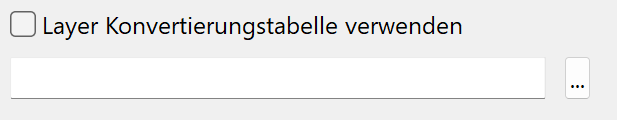
With the help of this option and an appropriate Excel file, the layers from the construction parts can be divided even further apart, either in another layer or with a layer name extension.
ON: A selected Excel file is used as a template for the conversion.
OFF: No additional layer conversion is made.
An example file (layerconv.xls) can be found under <ELITECAD-installation-path>\u\<version>\int\dxf\dflt\ .

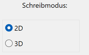
2D: Only 2D data will be saved.
3D: All data (2D + 3D) will be saved.
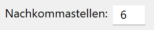
Specifying the precision of the numbers (decimal places) for the DXF file.
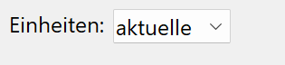
active: The units set in CAD are used.
mm: The data is exported in millimetres.
cm: The data is exported in centimetres.
m: The data is exported in metres.
ON: All ELITECAD attributes and layers are saved as DXF attributes. The ELITECAD attributes are saved as being converted 1:1 where the conversion file is not otherwise stated; in other words, the attribute id becomes the DXF attribute id.
The ELITECAD model, group, class, level * classifications are converted to the DXF attributes HD_PATTERN, HD_GROUP, HD_CLASS and HD_LAYER.
If the ELITECAD classifications or attributes are visible and only the ELITECAD text contains the classification or attribute names, these are saved as visible DXF attributes, or as DXF text and invisible DXF attributes. The invisible attributes are arranged one below the other in order to ensure an overview when changing visibility e.g. in AutoCAD.
OFF*: Only attributes from the DXF attribute group are saved.
ON: Infill hatches are saved as associative hatches (HATCH).
OFF: No infill hatches are saved.
After activating the switch, the following set-up dialog window appears.
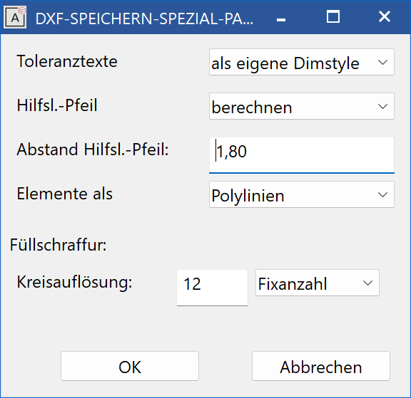
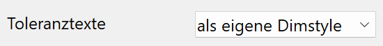
As personal text: The two-line tolerance text is generated separately from the dimensioning block as independent text with the same layer.
As personal dimension style: For every different tolerance text, a separate DIMSTYLE (dimension parameter) is generated.
In dimension block: The two-line tolerance text is also saved in the dimension block. Tolerance text is lost in AutoCAD if stretched.
![]()
calculate: The specified distance between the dimensions and the start of the dimension help line is used.
calculate: The distance is calculated from the dimension geometry and saved in the DXF dimension parameter. For architectural dimensions (constant length of help lines) the settings are useless because another distance is given for every dimension.
![]()
Value for the constant setting.

Lines + arcs: ELITECAD elements are saved as individual lines and arcs, e.g. 1 rectangle > 4 lines
Polylines: successive ELITECAD elements are saved as polylines, e.g. 1 rectangle > 1 polyline
( until ACAD Version12 )
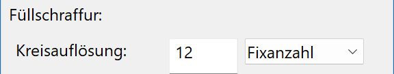
Circular resolution: Number of segments or curve lengths.
Fixed number: Number of segments for every full circle.
Curve length: Segment lengths in the active unit. To avoid unwanted results, the number of segments per arc in the program is limited to a minimum of three and a maximum of 100.
Default settings for the export
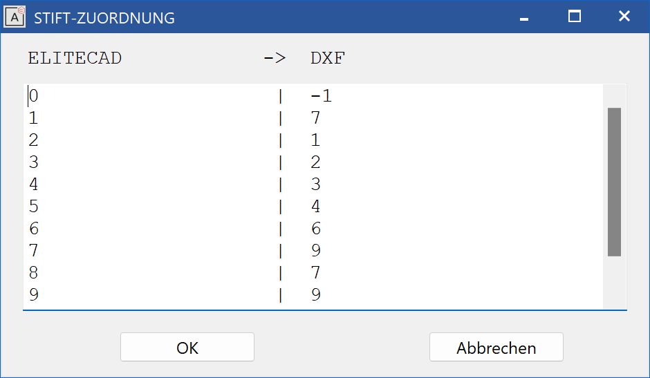
Tables > Export > Pens
This function is used to allocate the ELITECAD pens to the DXF colours.
Because Version 8 and higher of ELITECAD have over 1024 pens to choose from, whereas the DXF file format (and also AutoCAD) only has 256 pens, several ELITECAD pens must be assigned to a DXF colour. For this to work, ELITECAD has predefined conversion tables for IMPORT and EXPORT.
Consequently, and from the fact that the conversion tables were created based on the most similar colour, the pen numbers can be changed after EXPORT and subsequent IMPORT, e.g. ELITECAD pen no. 94 becomes ELITECAD pen no. 78 after DXF-EXPORT and subsequent DXF-IMPORT.
If this is not acceptable, separate entries for the desired pens must be created in the conversion tables, e.g. EXPORT 94 > 55 and IMPORT 55 > 94
Note
The DXF pen "-1" (minus 1) means that the respective ELITECAD pen is not saved into the DXF file.
The following must be noted when entering the desired allocation (this applies to all following tables):
- At least one blank space must be present between two values.
- The table is completed by an empty row.
- All entries after the empty row will be ignored.
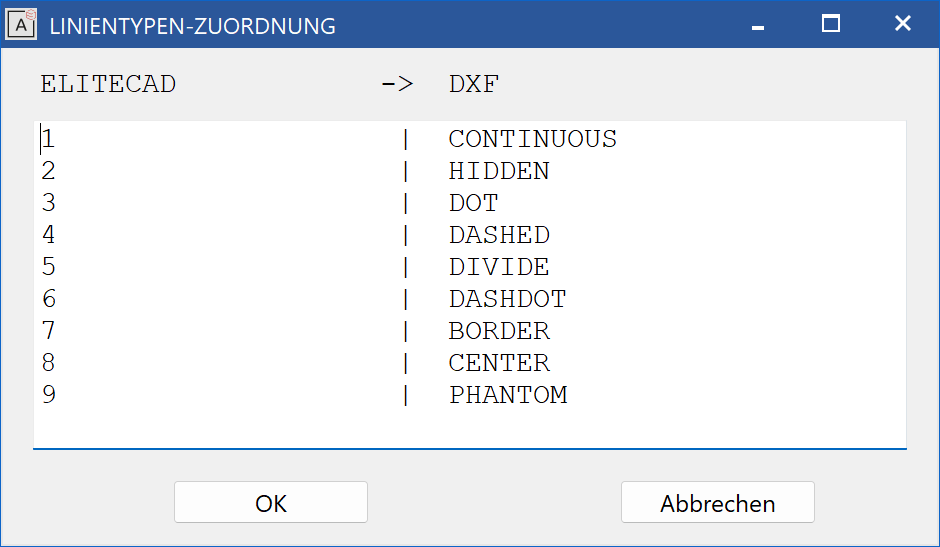
Tables > Export > Line types
This function is used to allocate the ELITECAD line types to the DXF line types.
Tables > Export > Characters
This function is used for the allocation of ELITECAD special characters to DXF text sequences (%%...) and other special characters.
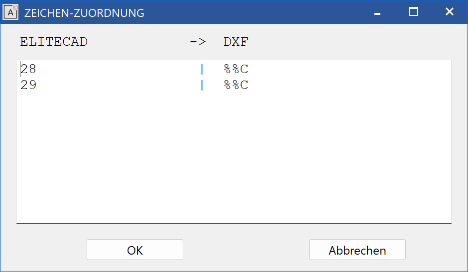
Note
"^5" stands for exponent 5 in the M,cm/mm dimensioning. Numbers 1 - 9 can be used here.
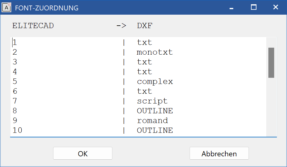
Tables > Export > Fonts
This function is used for the allocation of ELITECAD fonts to DXF fonts.
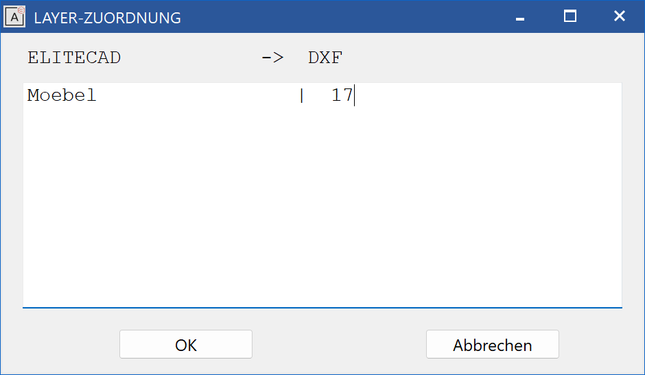
Tables > Export > Layer
This function is used for the allocation of ELITECAD layers to DXF layers.
After activating the function, the following set-up dialog window opens.
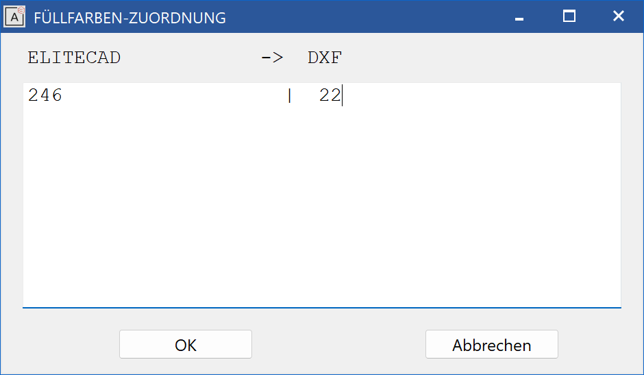
Tables > Export > Filling colours
This function is used to allocate the filling colours.