DXF/DWG – Import
|
|
Interfaces toolbar |
| File menu > Import > DXF/DWG |
Reading the information
In order to increase the quality of the imports, previous information can be read from the DXF file. The basic criteria of a DXF file are displayed on dialog windows and can be applied to the import tables. Both "CAD-Layer names" and "CAD-Block names" functions list the values from the active drawings on the screen. To read the information in a DWG file, the file must first be converted into a DXF file in a converter.
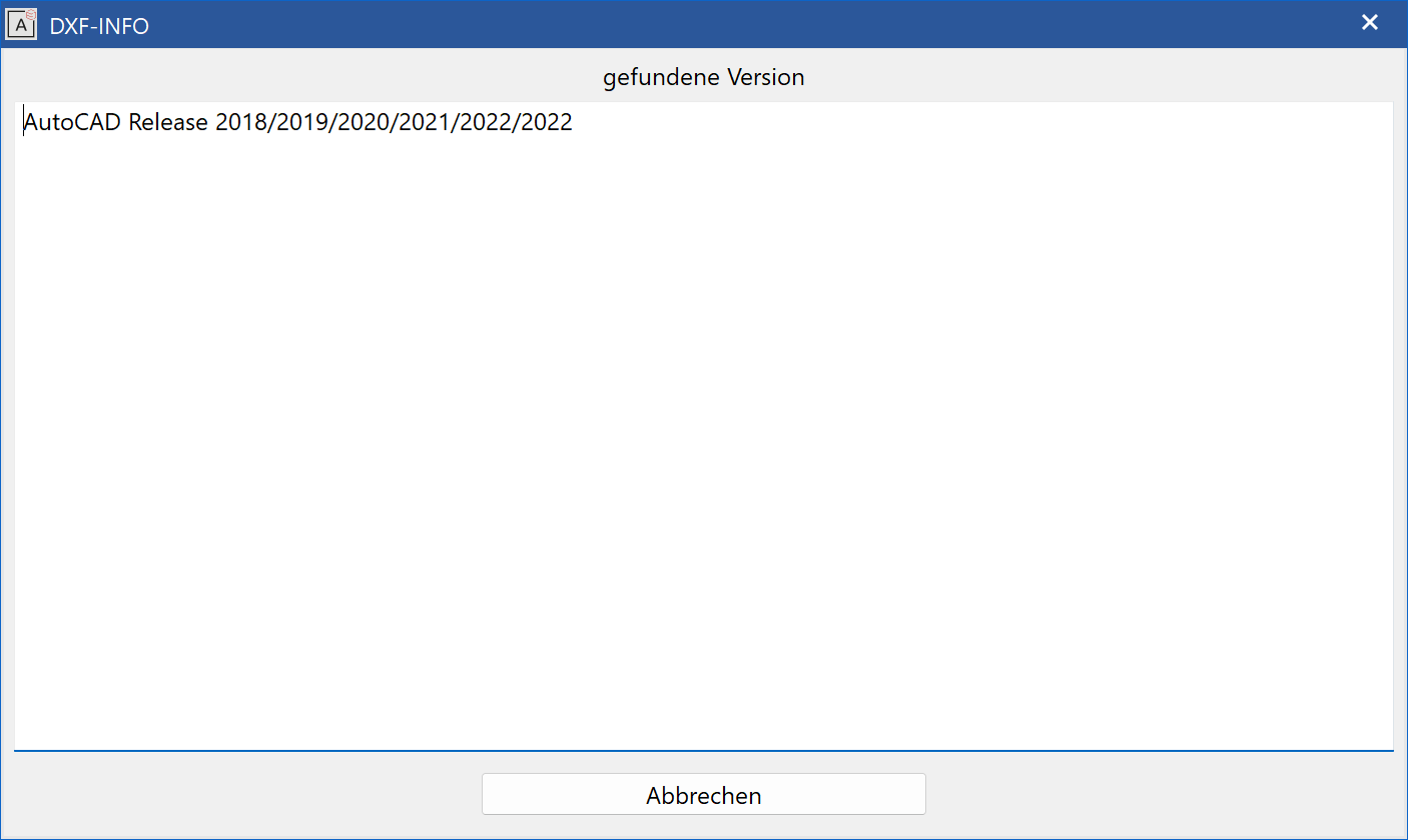
Show info > DXF-Version
This function is used to show the DXF-Version that is being used.
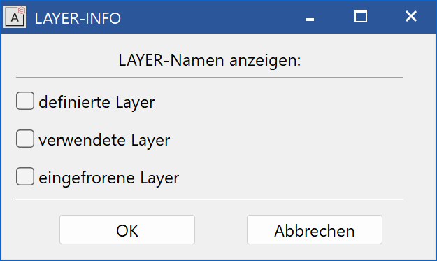
Show info > Layer
This function is used to show the layers that have been defined, are used or are frozen in DXF.
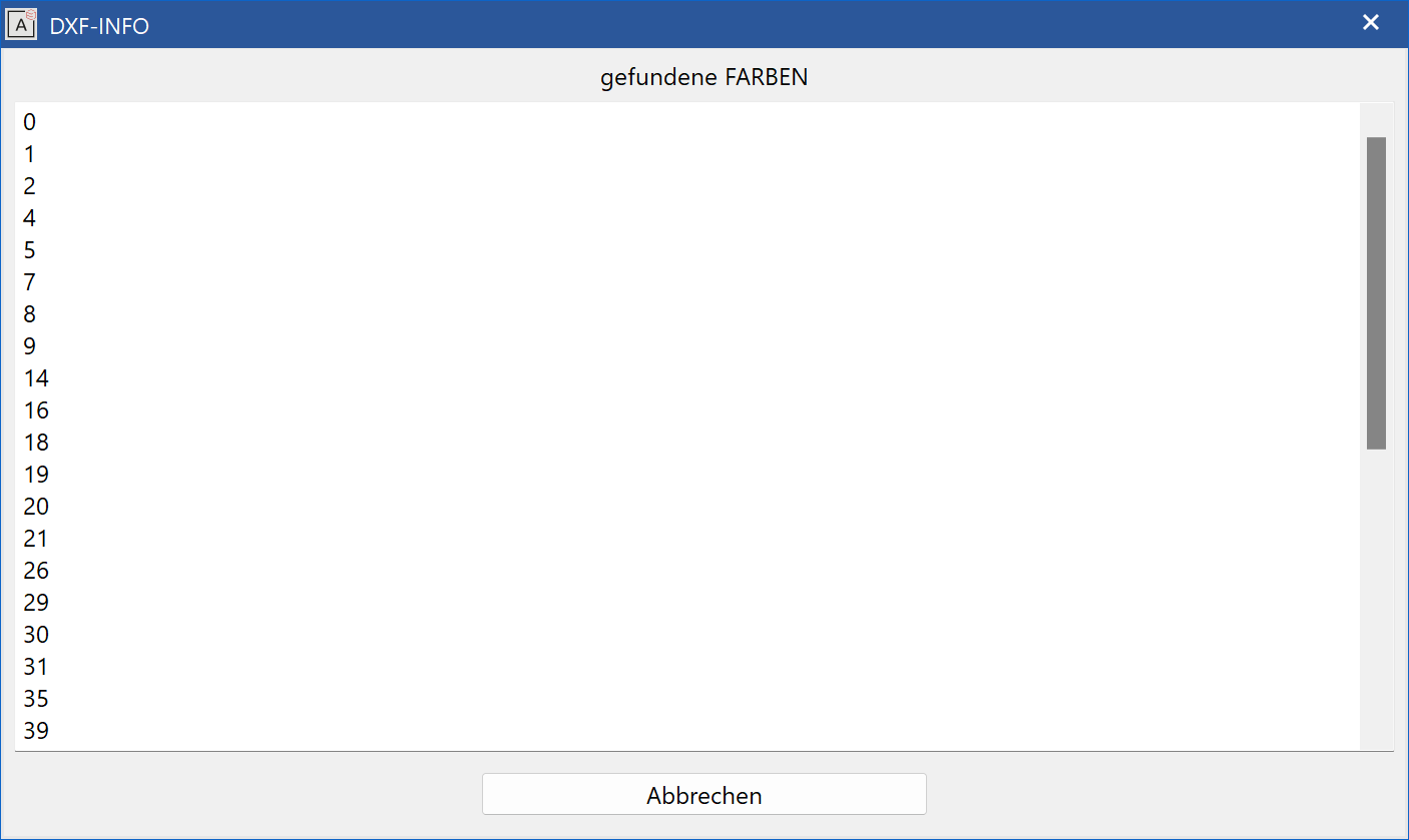
Show info > Colours
This function is used to show the colours used in DXF.
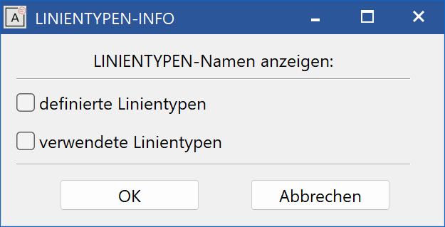
Show info > Line types
This function is used to show the line types that have been defined or are used in DXF.
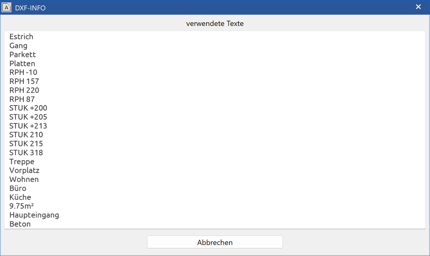
Show info > Texts
This function is used to show texts used in DXF. For special characters, the ASCII code is subsequently written in parentheses. If the characters are incorrectly imported, the character will need to be amended in the import tables.
Tip
Converting special characters:
When loading a file, the text reads as follows, for example: "10.95 m»"
This text should be changed to "10.95 m²".
All text in the DXF file can be listed with the SHOW INFO > TEXT function. Special characters' ASCII codes are marked with parentheses.
Result: "10.95 m» (253)" or "10.95 m (253)"
The character code for the special character in ELITECAD can be identified with the function HELP > CHARACTER SET. In this case, it is 178. Now all you need to do is insert 178 for the value 253, and upon reloading of the file, "10.95 m²" will appear instead of "10.95 m»".
Show info > Fonts
Shows the used DXF font definitions.
Show info > Fonts and texts
Shows the used DXF font definitions including the texts used.
Show info > Attributes
Shows the used DXF attributes and their content.
Show info > CAD-Layer names
Layers used in the active images are displayed in the info window.
Show info > CAD-Block names
Blocks used in the active images are displayed in the info window.
Main settings
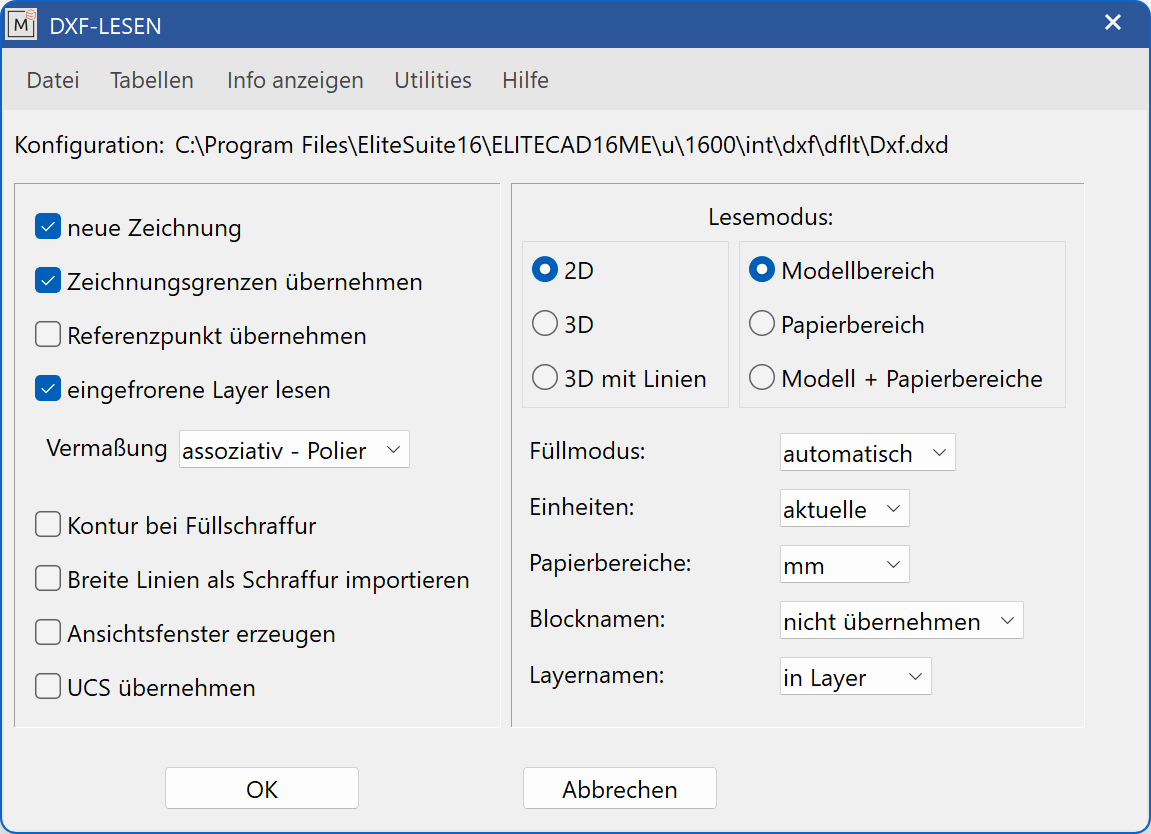

ON: A new drawing will be opened prior to the import.
OFF: The import of the file will occur within the currently open drawing.
ON: The maximal values saved in the DXF file are applied to the drawing dimensions. These drawing boundaries determine the scale, which is set, in case the active scale is too small.
OFF: The drawing boundaries are automatically calculated.

ON: The drawing's origin saved in the DXF file is used.
OFF: The drawing is centred.

ON: Layers that are marked and saved in DXF as frozen (meaning: hidden) are read.
OFF: Only "visible" layers are read.

Associative - M,Cm/mm. The dimensioning including exponents is associatively applied in full.
associative: The dimensioning is associatively applied in full. Dimensions, which are not available in ELITECAD, can be incorrectly converted.
free: Non-associative dimensioning is generated. This is fully handled as dimensioning but not corrected after block stretch.
Line + Text: Dimensions are converted to lines and text.

ON: A contour of the infill hatch is displayed.
OFF: No contour of the infill hatch is displayed.
New · 16 R3 · Improvements
ON: Broad lines are represented in ELITECAD as a hatch.
OFF: Broad lines remain lines and follow the user-defined conversion for ELITECAD. This is set in the Tables > Line types

ON: A view window is generated when reading the paper space.
OFF: No view window is generated.

User-defined coordinate system (German BKS, English UCS)
ON: A coordinate system defined by a user becomes the standard coordinate system.
OFF: The standard coordinate system is applied.
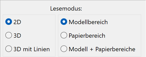
2D: Only 2D data can be read.
3D: Both 2D and 3D data can be read.
3D with lines: 3D information, which does not create 3D objects (for example, height markers), is taken into account.
Design model range: If this check box is ticked, the design model range can be read.
Paper space: If this check box is ticked, the paper spaces can be read.
Model + paper space: If this check box is ticked, the design model range and all present paper spaces can be read. Paper spaces are automatically converted to plots and listed in the views manager.

automatic: after every ACAD setting
ON: Infill hatch is automatically generated.
OFF: No infill hatch is created.

Because no units have been saved in the DXF file, the correct unit can be selected here.
active: The units set in CAD are used.
mm: Data is read in millimetres.
cm: Data is read in centimetres.
m: Data is read in metres.

A separate unit can be chosen for the paper space (plot view).
active: The units set in CAD are used.
mm: Data is read in millimetres.
cm: Data is read in centimetres
m: Data is read in metres.

in model name: The block names are used as model names.
in Attribute block: The block names are saved in the "block" attribute.
do not adopt: The blocks are not adopted.
Note
If the IN ATTR. BLOCK option is selected, an attribute file needs to have been loaded beforehand.
Start the ATTRIBUTE-PARAMETER function from the ATTRIBUTES toolbar, enter the following path into the entry row

in group: The layer name is attributed to the classification GROUP.
in class: The layer name is attributed to the classification CLASS.
in level: The layer name is attributed to the classification LEVEL.
in layer: The layer name is saved in the layer attribute and the layer manager is automatically made available.
Default settings for the import
Tables > Pens
This function is used to allocate the DXF colours to the ELITECAD pens.
An ELITECAD pen is allocated to a DXF pen in the set-up dialog window. All of the non-listed "DEF" pens are allocated in this case to Pen 10 in ELITECAD. The table can be extended in any way and saved as a new configuration.
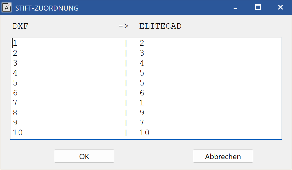
The following must be noted when entering the desired allocation (this applies to all following tables):
- At least one blank space must be present between two values.
- The table is completed by an empty row.
- All entries after the empty row will be ignored.
Tables > Line types
The line types defined in DXF are allocated a line type number. The table can be extended in any way and saved as a new configuration.
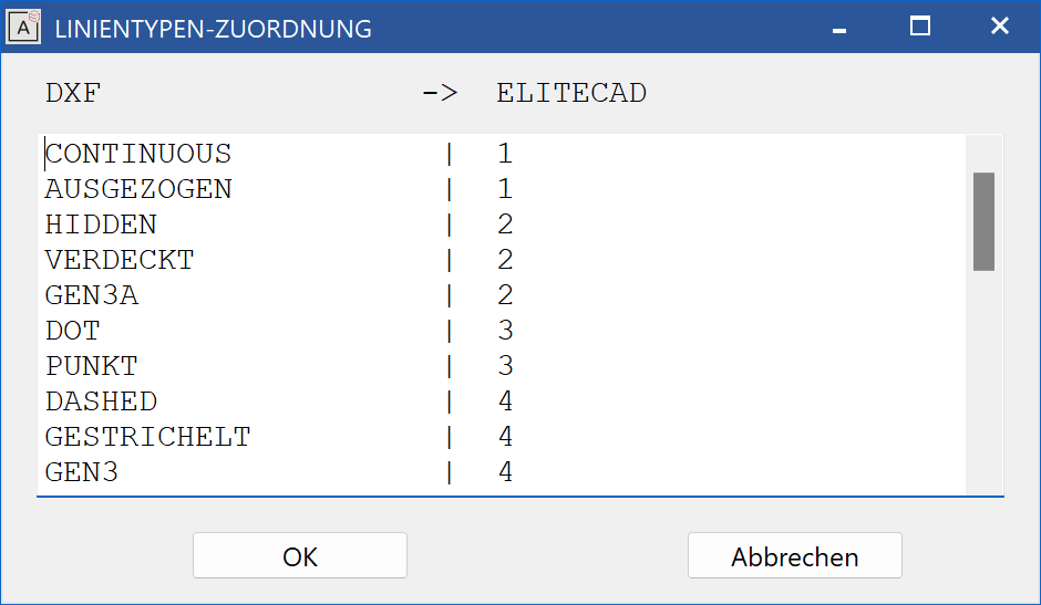
Undefined line types are automatically assigned as line type 1.
Tables > Characters
This function is used for the allocation of DXF text sequences (%%..) and special
characters to the ELITECAD ASCII code. The table can be extended in any way and
saved as a new configuration.
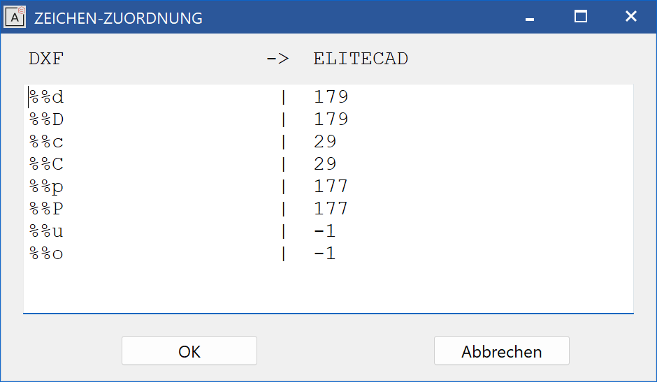
Note
The ELITECAD character "-1" (minus 1) means that the relevant DXF character is deleted.
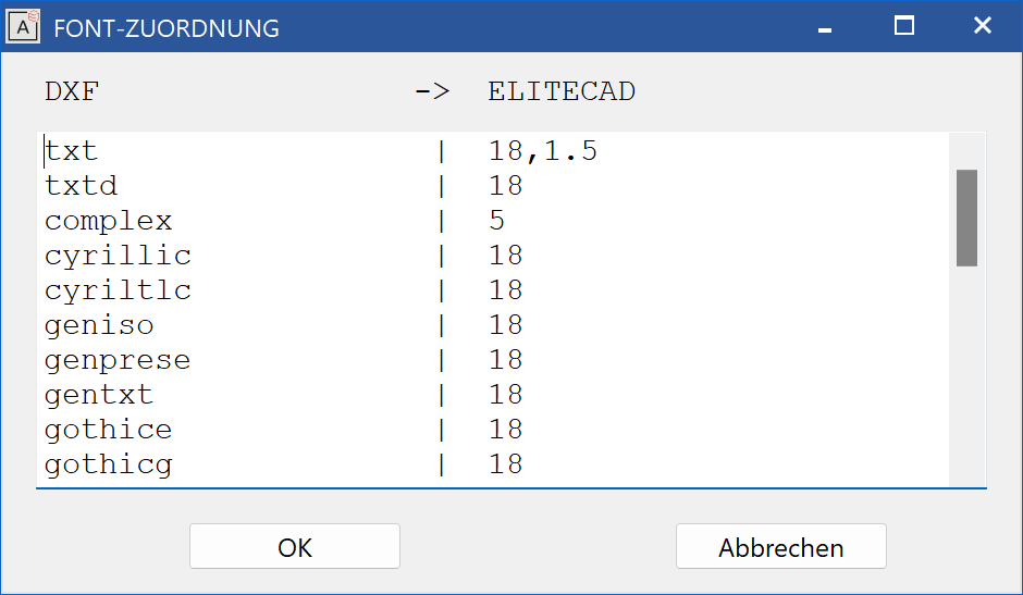
Tables > Fonts
This function is used to allocate DXF fonts to ELITECAD fonts with optional character width (space) separated from the font number by a comma. The table can be extended in any way and saved as a new configuration.
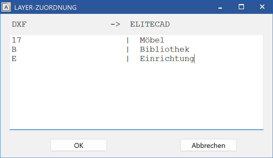
Tables > Layer
This function is used to allocate the layers. The table can be extended in any way and saved as a new configuration.
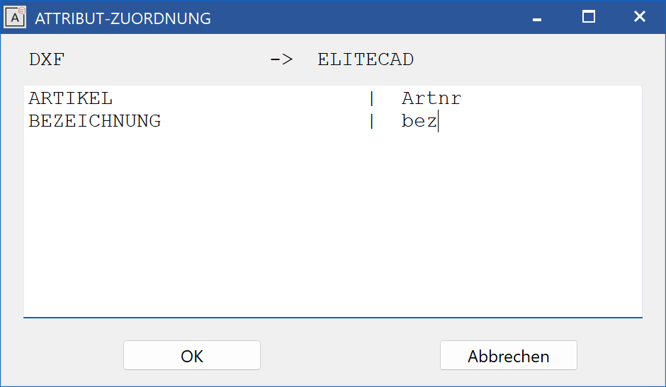
Tables > Attributes
This function is used to allocate the DXF attributes to ELITECAD attributes. The table can be extended in any way and saved as a new configuration.
Tables > Filling colours
This function is used to allocate the filling colours.
(According to the allocation in the pen colour table)