Views

The views are generated 2D plans.
Editing of views is described in the chapter EDIT VIEWS.
Header functions for the views
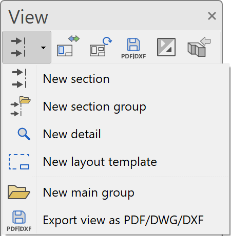
| Function | Description |
|---|---|
| New section | |
| New detail | |
| New plot | |
| New layout template | |
| New main group | |
| Modify | |
| Refresh | |
| 3D edit mode (only in ELITECAD Architecture) | |
| export as PDF/DWG/DXF | |
| Expand/Close all view groups |
Context menu of a view
If you right-click on a created view, the following options are available:
Show view in a new window
![]() Details in OUTPUT > VIEWS > FUNCTIONS IN VIEWS.
Details in OUTPUT > VIEWS > FUNCTIONS IN VIEWS.
Float view window
Details in OUTPUT > VIEWS > FUNCTIONS IN VIEWS.
Rename
Details in OUTPUT > VIEWS > FUNCTIONS IN VIEWS.
Delete
Details in OUTPUT > VIEWS > FUNCTIONS IN VIEWS.
Create copy
Details in OUTPUT > VIEWS > FUNCTIONS IN VIEWS.
3D edit mode (only available in ELITECAD Architecture)
Details in OUTPUT > VIEWS > FUNCTIONS IN VIEWS.
Separate view (only available in ELITECAD Mechanics)
Details in OUTPUT > VIEWS > FUNCTIONS IN VIEWS.
Refresh view
![]() Modifications to the model are included in the generation of the view. The last-updated design model data for the view is replaced by data from the current design model. Newly drawn 2D elements are retained, as are edited elements of refreshed objects (e.g. deletion lines).
Modifications to the model are included in the generation of the view. The last-updated design model data for the view is replaced by data from the current design model. Newly drawn 2D elements are retained, as are edited elements of refreshed objects (e.g. deletion lines).
Undesired elements are deleted or modified when post-editing a newly generated view. Instead of actually deleting the elements, the system draws "deletion lines" over the selected elements. These hide the original lines when refreshing. If the deletion lines are deleted, the original elements reappear after refreshing.
Tip
The deletion lines are automatically assigned a separate layer that can be hidden or displayed as required.
Tip
When working with the classification structure group/class/level, care has to be taken that newly drawn 2D data is not added to an object, which will be updated. For instance, the hatch should not be added to the contour model.
Export view
![]() Details in OUTPUT > VIEWS > FUNCTIONS IN VIEWS.
Details in OUTPUT > VIEWS > FUNCTIONS IN VIEWS.
Save PDF file
![]() Details in OUTPUT > VIEWS > EXPORT VIEWS AS PDF/DWG/DXF.
Details in OUTPUT > VIEWS > EXPORT VIEWS AS PDF/DWG/DXF.
Modify view
![]() Details in OUTPUT > VIEWS > FUNCTIONS IN VIEWS.
Details in OUTPUT > VIEWS > FUNCTIONS IN VIEWS.
Create new view
|
|
Views manager > new view |
| Insert menu > View (view type) |
The currently set view angle on the model is displayed as a hidden line in 2D form. Hidden line means that all visible edges are rendered.
Tip
WORK PLANE ON SURFACE can also be used for generating a facade and the function VIEW POSITION used for a perspective view of it (See chapter (Image properties).
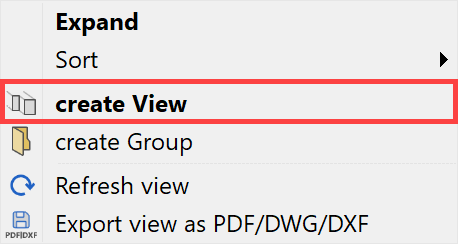
A new view can be generated using the corresponding header function or from the context menu of the views if a design model view is selected.
The desired settings have to be entered in the settings dialog window of the view. By clicking on  , the settings are saved and the view is created. The function MODIFY VIEW allows a change to the settings of the view after creation.
Settings of a view
General parameters
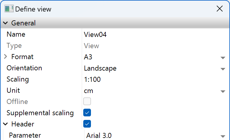
Name
Details in OUTPUT > VIEWS > GENERAL VIEW PARAMETERS.
Type
Details in OUTPUT > VIEWS > GENERAL VIEW PARAMETERS.
Format
Details in OUTPUT > VIEWS > GENERAL VIEW PARAMETERS.
Orientation
Details in OUTPUT > VIEWS > GENERAL VIEW PARAMETERS.
Offline
Details in OUTPUT > VIEWS > GENERAL VIEW PARAMETERS.
Rest scaling
Details in OUTPUT > VIEWS > GENERAL VIEW PARAMETERS.
Title
The title can be switched on or off.
ELITECAD Architecture uses the name of the view as a title. The text parameter of the title can be specified.
ELITECAD Mechanics uses a predefined text block for the title. Depending on your choice, the name of the view, the type of the view or the scale could be used. The text blocks are saved as templates in the directory <ELITECAD installation path>\u\<version>\me\glob\symbols\title and are selected by their name. The text parameters are taken from the template.
Title position
In ELITECAD Architecture, the title is positioned centred above the view.
In ELITECAD Mechanics, the view title can be positioned centred below or centred above the view when creating the view. If the title is moved afterwards in the graphics window, this is shown as a free position in the menu. The view title position is maintained during regeneration of the view. A free position may be reset manually.
Tip
The title of the views can be moved individually in the plots.
View specific parameters
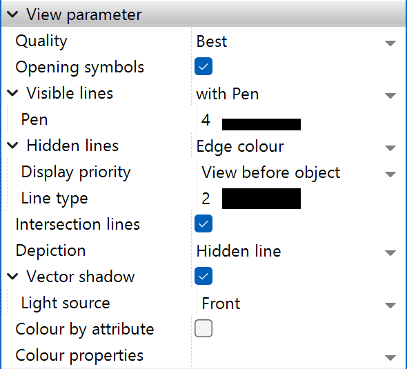
Quality
The higher the quality set, the higher the precision of the rendering. The rendering time increases, however.
Options: Preview, Fast, Exact in ELITECAD Mechanics.
The setting PREVIEW uses a fast calculation method to detect the visibility of edges. As a result of the rounding methods used for this, small errors may occur at the boundaries of curved surfaces.
The setting FAST uses the data that are used for the display to detect the visibility of edges. This 3D data depends on the RESOLUTION setting, which means that boundaries of round surfaces are approximated by lines. If possible, arcs are used but the precision is not guaranteed. Just like in in the setting PREVIEW there is no correct treatment of tangential transitions possible.
The setting EXACT uses the analytical description of the geometry to determine the visibility of edges.
Opening symbols
This option is only available in ELITECAD Architecture. If this option is selected, the opening symbols are automatically displayed in the rendered view. The opening types must be set in "Tool for window division/muntins" of the individual windows.
Visible lines
Users can select between two options:
All with the same pen or the pen is adopted from the edge colour.


Hidden lines

All edges that are behind the visible surfaces can be displayed in a specific pen and line type.
Display priority
This option is only available in ELITECAD Architecture.

With the setting OBJECT BEFORE VIEW the invisible lines of a 3D object are displayed in accordance with the representation level parameters of the 3D object.
Tip
With the setting OBJECT BEFORE VIEW the invisible lines of individual objects can be displayed, although they are generally deactivated in the view.
Intersection lines
If two 3D objects intersect, the resulting intersection lines are created with this check box.
In ELITECAD Mechanics no intersections lines are calculated when the quality setting is set to EXACT. Objects that intersect each other may produce wrong results with this setting. Intersection lines have to be generated as real edges of the object using the 3D editing functions.
Tangential transitions
This setting is only available in ELITECAD Mechanics.

All visible edges (surface boundaries) that do not represent sharp edges can be depicted in an individual pen and line type. (e.g. transition between a planar surface and a cylindrical surface). Transitions between two surfaces of the same type (e.g. two halves of a cylinder) are never depicted.
This option is only available for the quality setting EXACT.
Hidden tangential transitions are depicted with the settings for invisible lines.
Centre lines
This setting is only available in ELITECAD Mechanics.
When this option is active, centre lines from the design model are depicted.
Depiction

This menu can be used to determine whether a solid image or a render image is stored in addition to the lines for the view.
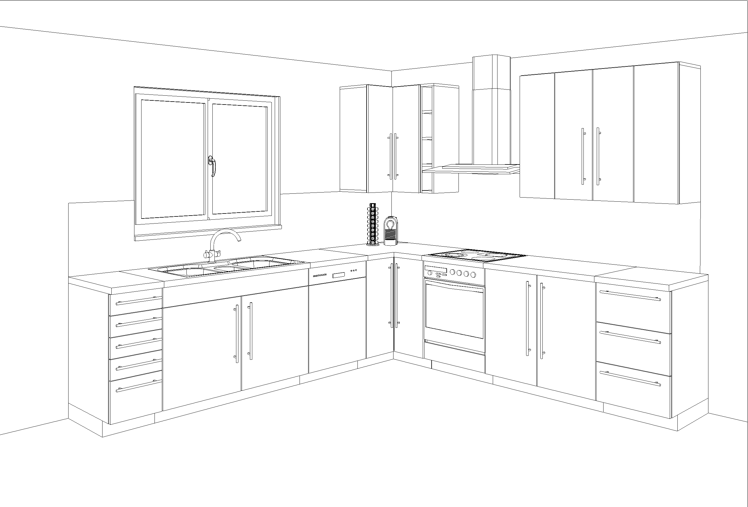
Hidden line
Only lines are displayed.
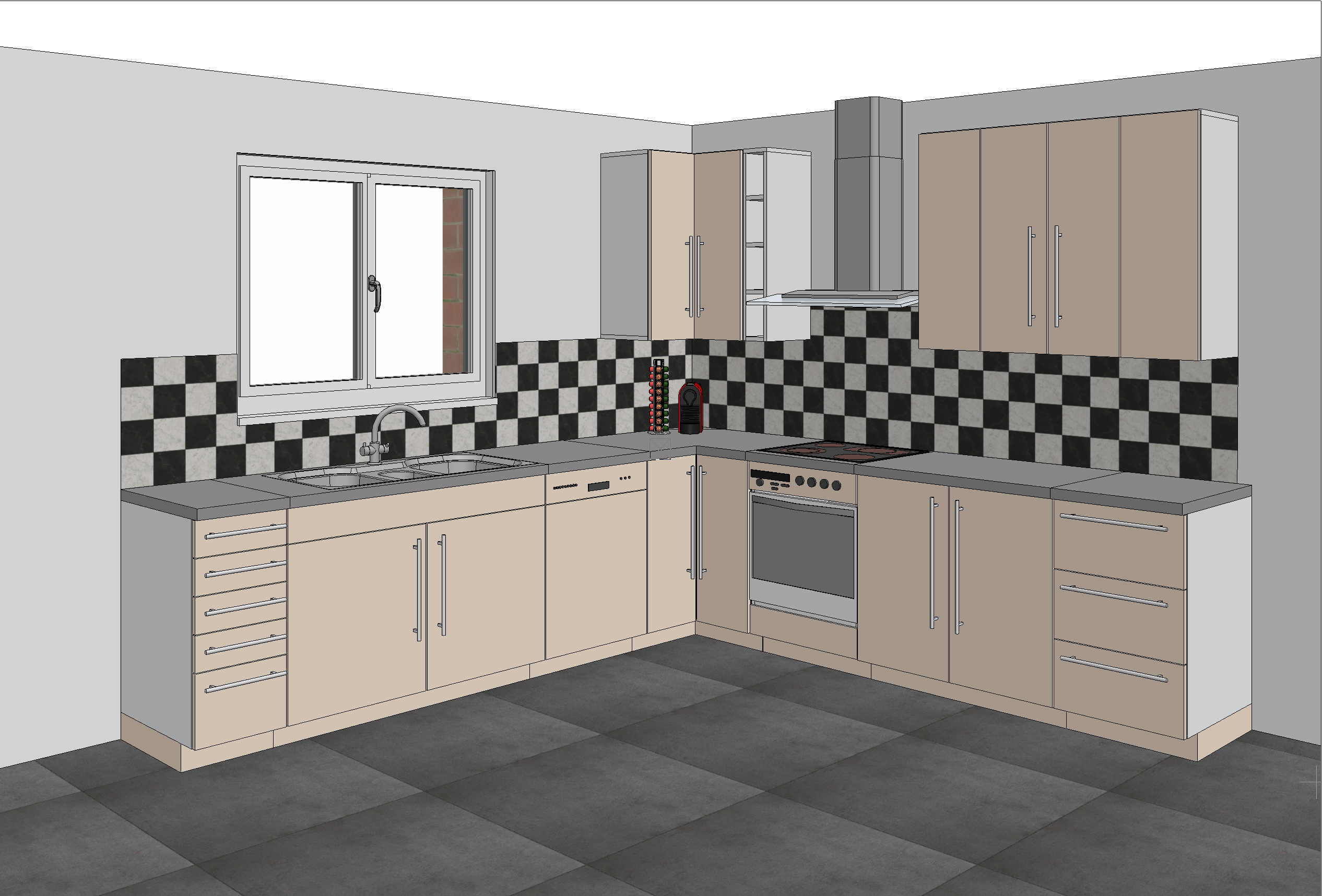
With solid image
The colour surfaces are added to the background of the line depiction.
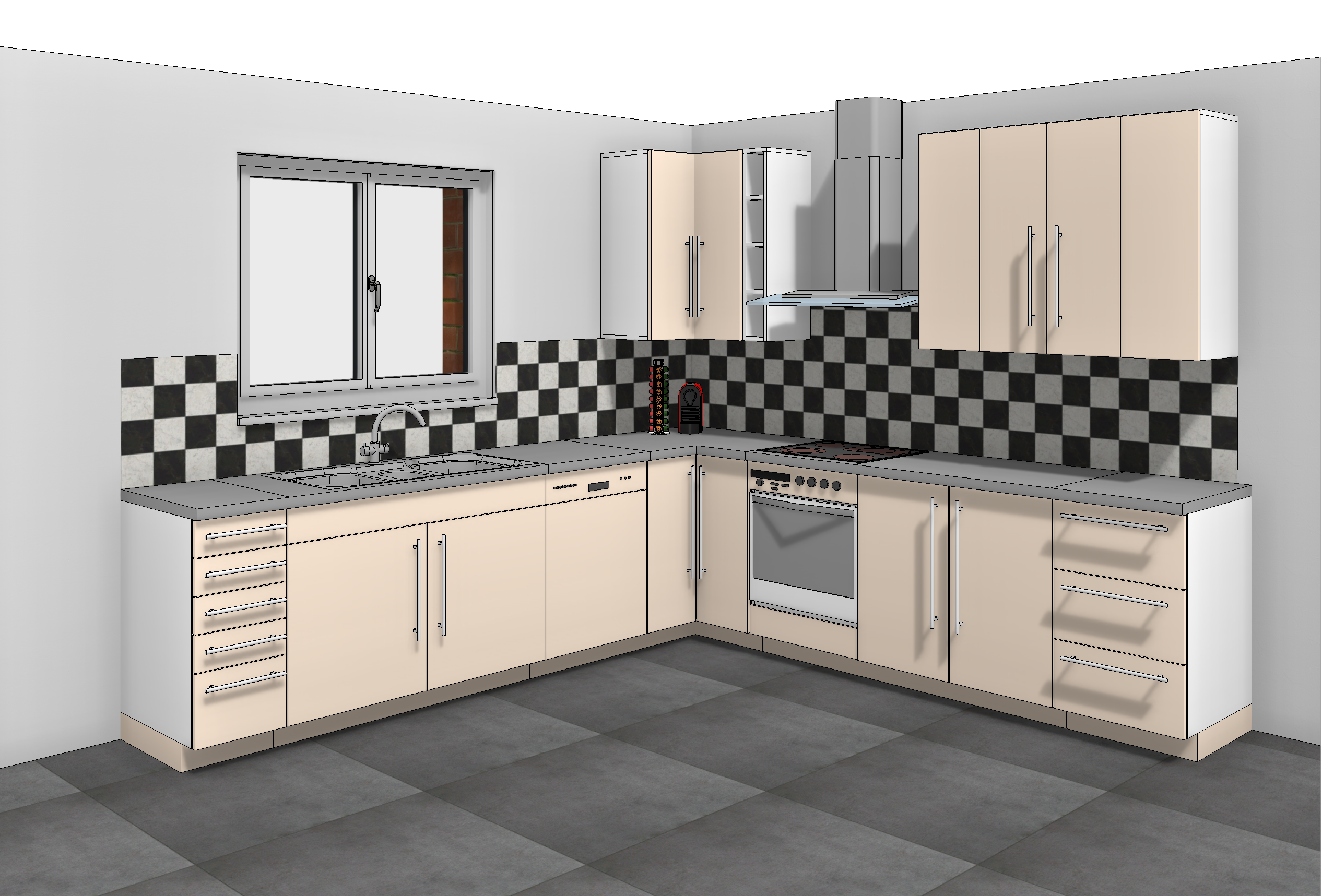
With solid image in shader mode
Improved · 16 R1 · Improvements
The colour surfaces in shader mode are added to the background of the line depiction.
With render image
The render image is added to the background of the line depiction.
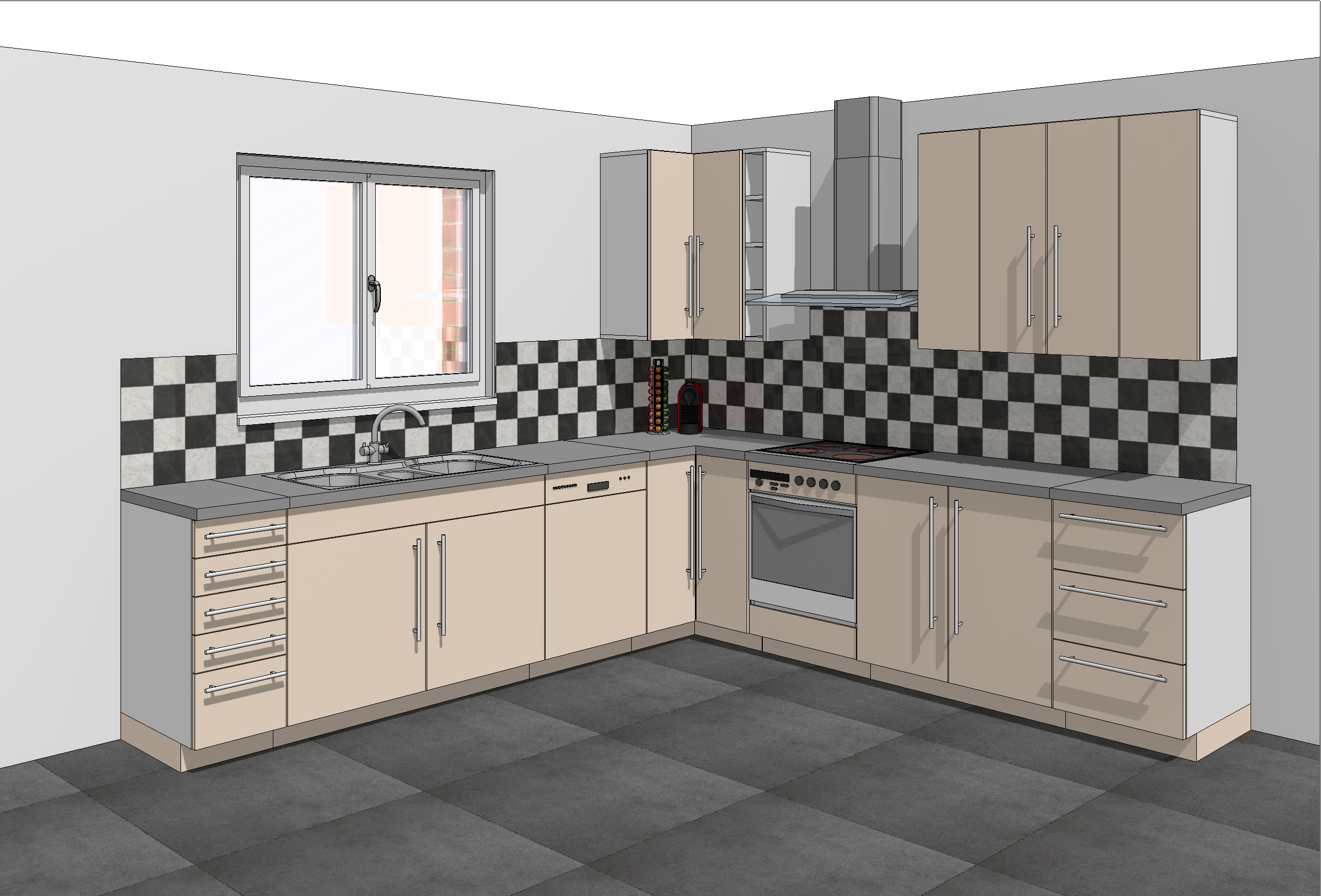
If "Render" is selected, rendering parameters also appear.
Render parameters

The render parameters can be opened directly or the saved records called up here.
Vector shadow
This option is only available in ELITECAD Architecture.

In order to render a vector shadow, a light source with the light type "parallel light or sun" must be present. This must be set beforehand in the LIGHT PARAMETERS. The "parallel light" may not be "camera relative" but must have a fixed position. If there is no such light source, the selection field remains blank and no shadow can be rendered.
The orientation of the light source can be changed at any time in the LIGHT PARAMETERS.
Tip
Create a separate light source for each view. This is the only way to set an optimal position of the sun for each individual view. If you use the same sun for each view and keep moving the position, you will not be able to refresh the views without the sun position changing.
Users can select which layers cast or receive shadows in SETTINGS menu > OPTIONS > VIEWS > VECTOR SHADOW. The hatch parameter that is used for the shadow can also be set here.
Colour by attribute
Details in OUTPUT > VIEWS > GENERAL VIEW PARAMETERS.
Colour scheme 
Improved · 16 R1 · Improvements
Details in OUTPUT > VIEWS > GENERAL VIEW PARAMETERS.
Renovation planning (only in ELITECAD Architecture)

Object state
Details in OUTPUT > VIEWS > GENERAL VIEW PARAMETERS.
Fillings
Details in OUTPUT > VIEWS > GENERAL VIEW PARAMETERS.
Demolition objects
Details in OUTPUT > VIEWS > GENERAL VIEW PARAMETERS.
Visibility (only in ELITECAD Architecture)

Layer types
Details in OUTPUT > VIEWS > GENERAL VIEW PARAMETERS.
Hull depiction
Improved · 16 R1 · Improvements
Details in OUTPUT > VIEWS > GENERAL VIEW PARAMETERS.
General functions
Storey division lines
This option is only available in ELITECAD Architecture. The storey division lines and vertical division lines of walls and columns disappear if the same material has been selected.
Functions in the graphics window context menu
Define, modify or delete cut-out
Details in OUTPUT > VIEWS > FUNCTIONS IN VIEWS.