Checking the ELITECAD Model
Check room contours
The following rules need to be complied with in order to be able to determine the room contours of the CAD:
- Room-dividing elements must not overlap.
- No room divisions along room-dividing walls or room-dividing glass elements.
- No room-dividing building components such as walls or glass elements with the active option ROOM DIVIDING may be placed above each other. This option is allowed to be selected for only one building component.
Show room separating objects
|
|
Menu Extras > Quantities > Show room separating objects |
All room-dividing building components of the current story are shown.
Check room contours
|
|
Menu Extras > Quantities > Check room contours |
Assembly of room contours (model)
The desired storey has to be active. The contours are attributed to the layer "Room-check-contours".
Tip
The individual contours can be checked using the function VERIFY 2D MODEL (Menu INFORMATION) to determine if the contour is faulty (open).
Delete room contours
|
|
Menu Extras > Quantities > Delete room contours |
Room contours, which have been generated by the CHECK ROOM CONTUR function, will be deleted by this function.
Check wall axes
|
|
Menu Change > Wall > Change wall axes |
In order to ensure a correct quantification of the walls and the wall surfaces, it is important that all walls have been created correctly. The wall axes have to adjoin the wall contour.
Check outer contours
An outer contour is generated for every storey during the quantification.
These contours can be created using the layer "Outer contour".
These contours are only indicated if the outer contours are switched on: Activate "Outer contour" under SETTINGS > OPTIONS > DEPICTION > ARCHITECTURE.
Function of the height control
|
|
Menu Extras > Quantities > Quantities Manager > Settings/Rules button |
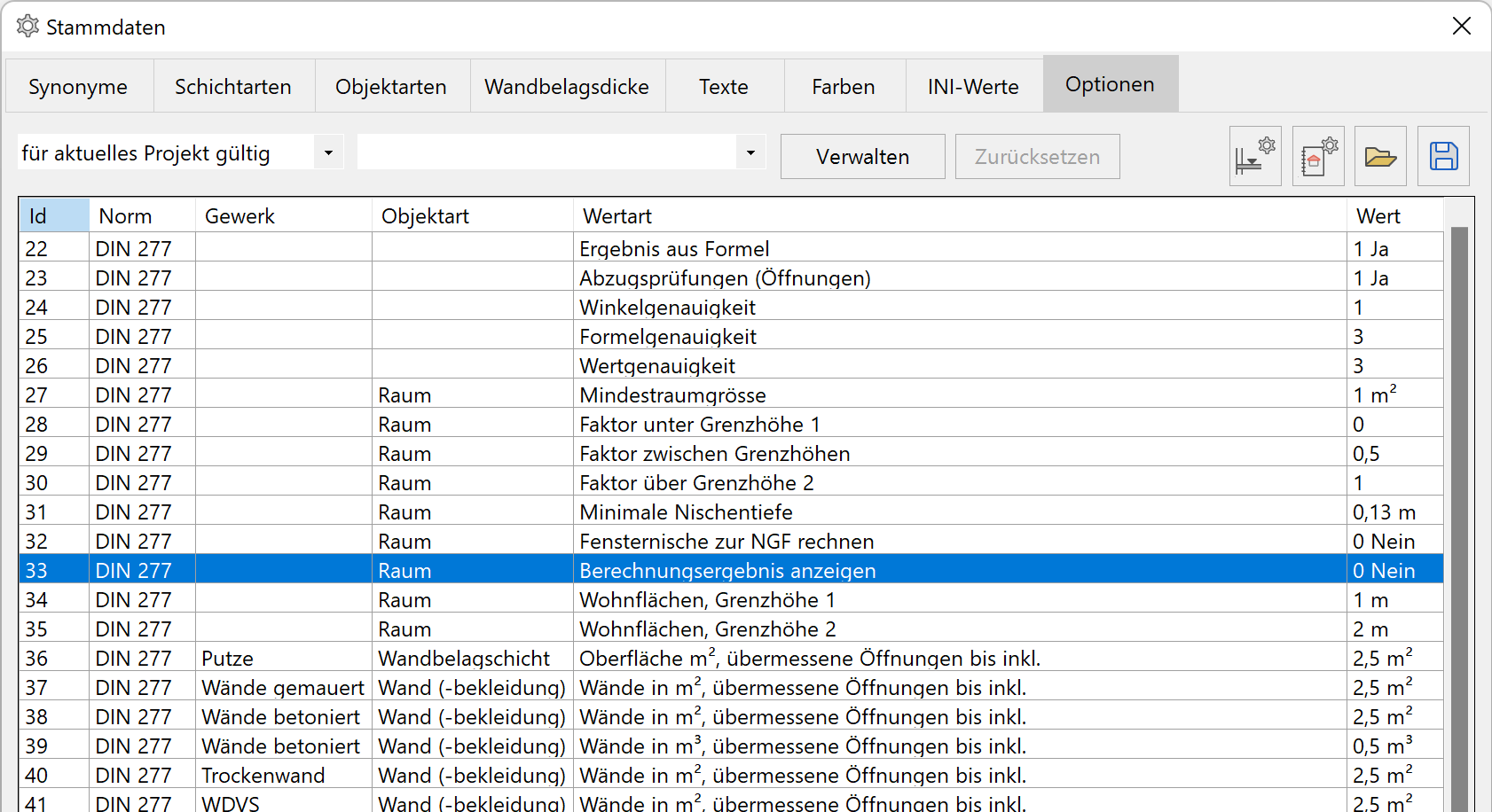
Under the Options tab, the option VISUALISE ROOM VOLUME should be set to 1.
New 3D-objects at the "further CAD layers" are generated during the quantification. If the option is reset to 0, these objects will be deleted during the next quantification.
These objects are only visible in the wire and solid model depictions. If these should be visible in a plan view, a hidden line over the Menu EXTRAS > HIDDEN LINE needs to be calculated in advance.
Layer Room boundaries:
Horizontal and vertical 3D-surfaces show the limitations of the room. The lower surfaces are located at the height BSTS. The setting MAXIMUM ROOM HEIGHT of the room definition is taken into account.
Layer Room boundaries _100%:
3D-surfaces at the height of the upper limit value for the calculation of living spaces.
The height is calculated starting from top edge FFL.
Layer Room boundaries_50%:
3D- surfaces at the height of the medium limit value for the calculation of living spaces.
The height is calculated starting from top edge FFL.
Layer Room boundaries_0%:
3D- surfaces at the height of the lower limit value for the calculation of living spaces.
The height is calculated starting from top edge FFL.
Layer Story boundaries:
Horizontal and vertical 3D-surfaces show the limitations of the storey.
The horizontal surfaces are located at the height of lower edge of the base slab (underside of the ceiling).