Tractrix curves
Now a guide line must be created or, if one already exists, selected. The program will lead the vehicle along this guide line in the manner set in the tractrix curve simulation.
Please note the input instructions in the bottom left of the status bar, above the CAD input field.
Select start point on the guide line with pen or <ABORT>
If the pen or the mouse is not used to tap the start or end point of a polygon, the direction in which the vehicle is to be moved must also be indicated for the system.
Show driving direction
If there is a branch along the guide line, the system will ask at this point in which direction it should continue.
Show driving direction (After abort, the guide line will be selected up to this point)
Tractrix curves parameters
After the desired guide line has been selected, the tractrix curve parameter window opens.
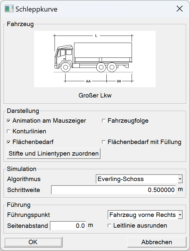
Vehicle
Under the vehicle section, the vehicle selected under Vehicle selection or the last-selected vehicle is displayed here. This vehicle is utilised for the current tractrix curve simulation. Clicking on the vehicle depiction (graphic) or on the vehicle name displayed below opens the Vehicle selection parameter window described in the Vehicle selection chapter.
Depiction
Under the Depiction section, 5 options are offered with regard to the presentation of the simulation result:
- Animation on mouse pointer
- Vehicle path
- Contour lines
- Area requirement
- Area requirement with infill
If Animation on mouse pointer is ticked, then once the simulation has concluded, an outline of the vehicle is attached to the mouse pointer and can show the vehicle position at each step of the simulation. This animation is ended with a left mouse click. The final position of the vehicle is then shown in the drawing. Esc ends the animation without the outline of the vehicle being included into the drawing.
The option Vehicle path inserts the outline of the vehicle into the drawing for each simulation step. The distance between the individual vehicle outlines is the same as the Increment selected under the Simulation section.
The option Contour lines causes the (outer) curves to be created and inserted into the drawing in order to show the points of the vehicle outline. These vehicle outline points include those of both the vehicle as well as the trailer:
- The front corner points
- The outer-most points of the rear axle
- The rear corner points
The front corner point defines the turning radius diameter, the outer-most point of the rear axle represents the smallest possible inside for the curve and the rear corner point forms the lateral deflection when driving in the curve.
The option Area requirement ensures that the needed areas to complete the simulation of the chosen vehicle combination is depicted as a closed polygon.
The option Area requirement with infill functions exactly as Area requirement but fills the newly-created, closed polygon with an infill.
As a rule for these and other groupings, the user can opt to apply one or more attributes or none at all. The Assign pen and line types button opens a small extra parameter window that allows for a selection of pen colours and line types to be applied to the resulting depictions.
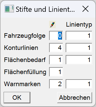
The pen and line type for warning markers can also be selected in this parameter window. Warning markers are added by the program to highlight areas, where the vehicle of the chosen type cannot follow (e.g. the defined turning radius diameter of) the given guide line. Warning marks will also be inserted into the drawing where the guide line could not be automatically rounded by the system when the Round guide line option was selected.
Simulation

In the Simulation section, you can choose between the two implemented simulation algorithms Tenner and Everling Schoss. With Tenner, the tractrix curve will be calculated with the graphing technique of the Tenner method.
The method according to Everling und Schoss is based on the numerical solution of a differential equation supported by the one-step method according to Runge-Kutta, which describes the connection between the tractrix curve and the guide point.
The results of the two simulation algorithms differ only slightly. With an increment of 0.5 m, the vehicle is towed a little further in using the Tenner simulation algorithm than when using the Everling und Schoss method. If the increment is reduced to 0.1 m, only a very small difference to the simulation with an increment of 0.5 m can be determined with the simulation algorithm according to Everling und Schoss. The calculated tractrix curve according to Tenner with an increment of 0.1 m comes closer to the result of the simulation according to Everling und Schoss (0.5 m and 0.1 m increments).
When selecting the increment, it is generally the case that smaller increments produce more accurate results. However, the following should be noted:
- Reducing the increment from 0.5 m to 0.1 m only makes a barely visible difference in the Everling und Schoss simulation.
- If the increment is reduced from 0.5 m to 0.1 m, around. 5 times as many drawing elements are inserted into the drawing.
- A simulation with an increment that is five times smaller also takes about five times as long to render.
- Even with a very small increment, the driving behaviour of the vehicle in reality cannot be reproduced exactly. In this case, the calculated drag curve should always be considered with a small safety margin (e.g. according to FGSV between 0.25 m and 0.50 m, depending on the range of motion).
For the maximum permissible increment, the simulation algorithms used must always be less than half the drawbar length. There is no solution for the simulation algorithm for larger increments. With the supplied truck ([FZ]AA=5280, [A1]AA=3410, [A2]AA=4840), the increment must be less than 0.5*[A1]AA=1.705 m. In order to be on the safe side, experience has shown that this increment should be slightly smaller. This is because it cannot be guaranteed that when the guide point is moved in exactly 1.7 m increments, that the coupling point of the towing vehicle will also move in exactly 1.7 m increments.
Guidance
In the Guidance section, one of three possible guide points:
- front centre axle,
- vehicle front left or
- vehicle front right
can be set for the vehicle. You can also specify before the simulation whether the guide line should be rounded with the turning radius diameter of the selected vehicle.
If vehicle front left or vehicle front right has been selected as the guide point, a side clearance to the guide line can also be defined. That means that road edges (curb) that are already polygons can be used as guide lines.
© GEO DIGITAL GmbH