Functions
All functions for Drainage are exactly described in the ELITECAD online Help Center in the Drainage chapter. You can at any time read how a function is used and what settings are required.
Function links to Help Center
| Function | Description |
|---|---|
| Load point | |
| Chamber | |
| Piping | |
| Slope calculation | |
| Set height | |
| Dimension | |
| Set drop | |
| Raise/lower load points | |
| Three-line | |
| Labelling | |
| Parts list | |
| Remove error marking |
Reference plan
A reference plan is an ELITECAD drawing already created that is inserted "behind" the actual new drawing. All elements will be displayed in one colour only. When drawing you can access all of the capturable points in the reference drawing.
Whilst creating a template with auxiliary lines may be sufficient for smaller objects, for larger drainages it is very helpful to work with a reference drawing. The amount of work is no greater than when the drainage is traced out with auxiliary lines.
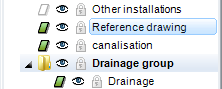
For the course example, the reference drawing was also stored in the "Reference plan" layer. The drawing can then be shown and hidden using the layer manager or the image properties parameter dialog. Additionally, all labelling of points are included in the reference plan.
Paste the reference plan
Menu INSERT > REFERENCE DRAWING
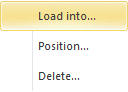
Load into… - Reference plan is imported into the saved storey Position… - Reference plan is imported into the active storey and can also be positioned Delete… - Delete and deactivate reference plan
Show/hide
The visibility can be set in the image properties parameter dialog.

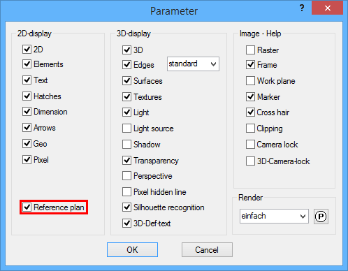
On: visible in image and printout
Off: hidden
Reference plan settings
Menu SETTINGS > OPTIONS
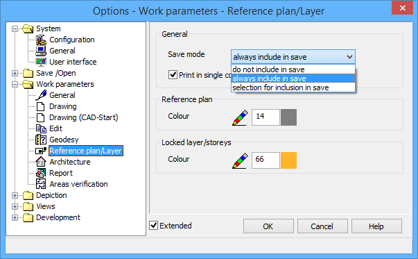
Save mode:
do not include in save
always include in save
selection for inclusion in save
Colour:
Colour number in which the reference plan is displayed