Preparation
Scope of function of the ELITECAD drainage module
Input functions

- LOAD POINT: The highest point of a circuit section (e.g. device connection, inlet)
- CHAMBER: Container at the lowest point of a circuit section. Type and measurements can be parameterised.
- CIRCUIT: The axis of a circuit is entered in the plan in the same way as a polygon.
- SLOPE CALCULATION: calculates the axis of the circuit in the room with the specified intended slope. Requirement: Load point and pipe axis are defined.
- DROP: Overcoming of height shifts with a specified angle.
- SET HEIGHT: Definition of a binding height in at a point of the circuit.
- RAISE/LOWER LOAD POINTS: Calculation of perpendicular circuit components independently of cross-section. Afterwards visible in the 3D model.
- THREE LINE: Generates the display of the circuit in the floor plan and in the model with all fittings and attributes.
- LABEL: Generates the label for the parameterised objects.
Automatic functions
Layer assignment of all components, bill of materials, height calculation as of +/- 0.00, sea level or as of current storey, error control.
Theory
The drainage module is based on standard products available on the market. As a result, possible nominal widths and the form of components such as pipes and chambers are predefined. Suitable minimal values for branchings are taken into account by ELITECAD.
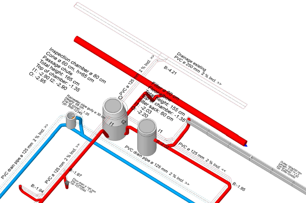
The detailing of the branching with the necessary 45° angle and connecting pieces is automatically performed by the drainage module. The result of a drainage drawn with the module is therefore always an automatically generated 3D module which can be checked with the corresponding Report.
Getting started
Workshop
In this course unit we start with the CAD_Object_Drainage.
First, load the project.
-
Open the project settings.
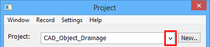
Select the project "CAD_Object_Drainage" and confirm it with .
.
- Load the corresponding model file by clicking FILE > OPEN from the menu. Select the model "Starting Position".
-
Menu INSERT > REFERENCE PLAN > LOAD INTO...
Import the prepared drawing "Reference.d".
Tip
Under SETTINGS > OPTIONS > WORK PARAMETERS > REFERENCE PLAN set the colour to 91 to better set the reference plan apart.
-
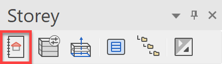
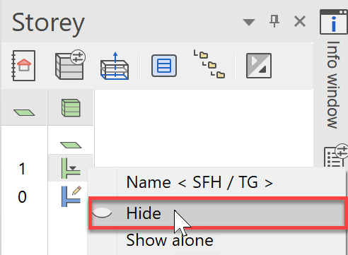
Hide the "TF" Storey.
In the Storeys manager, right-click on "TF" and select the option Hide.
-
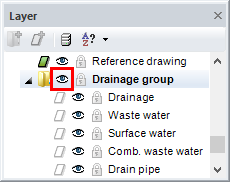
In the layer manager, show only those layers that you require for the next steps.
The layers; Room, Kitchen, Sanitary, Reference plan and the layer group Drainage group are needed.
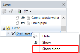
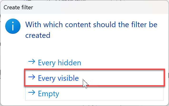
A filter for showing just this group can be created for later use to speed up your planning.
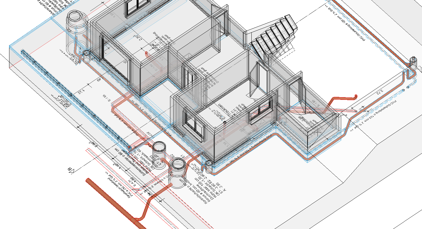
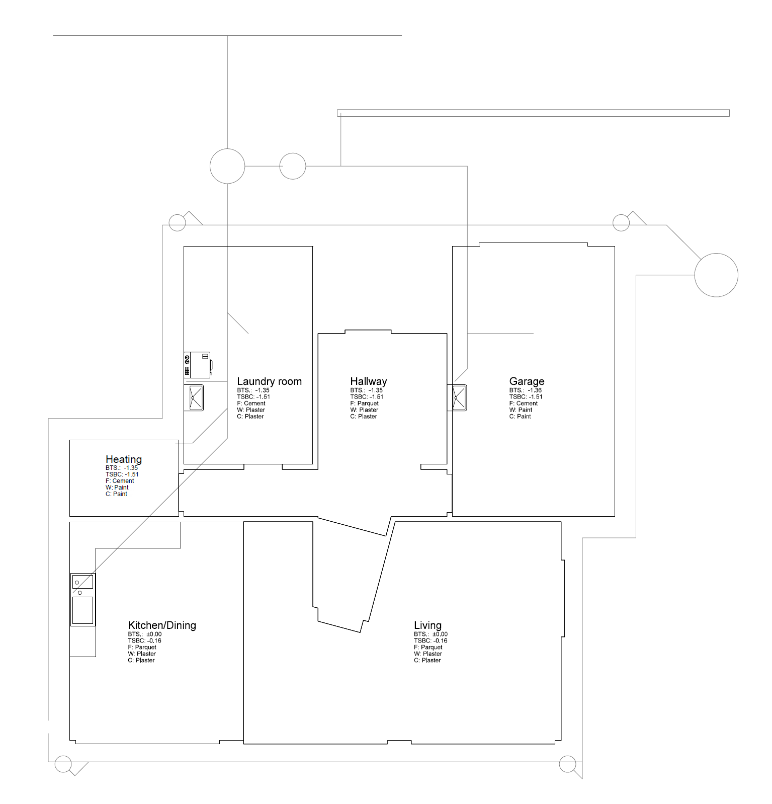
You should now see the following on screen:
A detailed description of the reference plan function can be found in the FUNCTIONS section of this course unit.