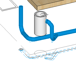
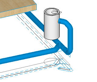
Rainwater trap
In the example, one rainwater pipe gully is connected with 45° and one with 90°.
Workshop
-
Apply the library part "rainwater pipe gully 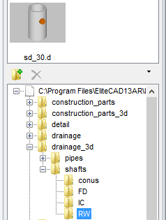
If the floor plan is to appear in the wire model, apply the solid view with Ctrl + D. In the library window under Drainage 3D > Shafts, click on the directory "RW" and on the drawing Sd_30.d that appears in the preview. The library part is now attached to the cursor. 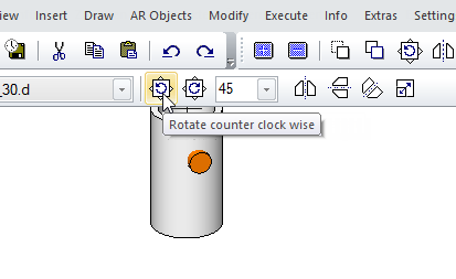
Turn the chamber anti-clockwise by 45°. 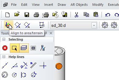
Insert the location method "ALIGN TO AREA/TERRAIN". 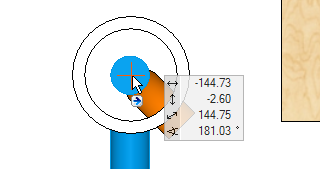
Now place the chamber on the top of the cleaning arm in P17. The chamber will now lie at the same height with +0.03. 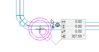
Click Ctrl + D to switch to the wire model and move the chamber to the centre of the circle of the template. -
Copy the rainwater pipe gully to the right-hand corner of the south facade.
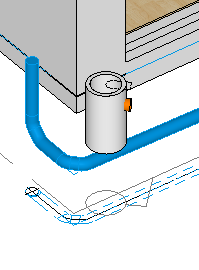
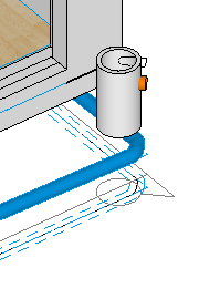
-
Load point for connection of the rainwater pipe gully

Apply the following values to the load points for both shafts:

Nominal width: 125
Connection height: -25 (connection lies 28 cm below the top edge of the shaft)
Height ref.: ±0.00
Conn.type: horizontal
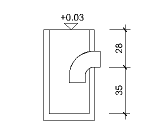
Rotate the model into the floor plan view with Ctrl + Space. In each case, set the load point at the intersection point of the rainwater pipe gully outer contour with the axis of the submerged trap.
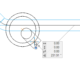
-
Circuit

For the two chambers, draw the circuit from the load point to the land drain pipe connection in P25 and P19 with the following values:

Surface water (predefined)
Nominal width: 125
Actual incline: 2%
Pen colour: 90
Line type: 1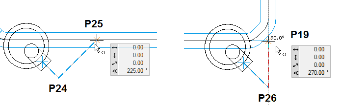
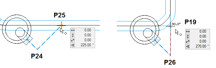
-
Slope calculation

The slope must be recalculated after the connection line has been added.
Click on the end point of the circuit for the seepage chamber in P23 and confirm the value of 2% for the intended slope.
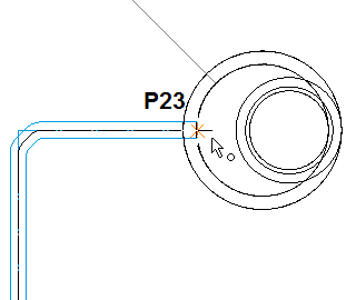
-
Set drop

Define the position and inclination angle for the drop for both shafts.Rotate the model into the 3D view and click on the pipe layout of the left-hand shaft just drawn, between P24 and P25. When the prompt Set slope at what point or \
for automatic? Appears, click on point P24 and then accept the proposed value for the height shift and the angle of 90.
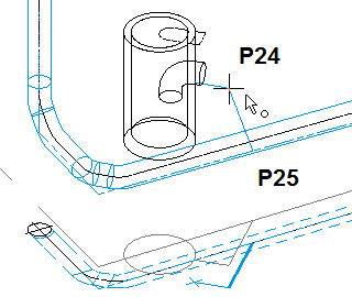
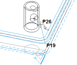
The vertical drop is inserted immediately. Apply the vertical drop between P26 and P19 for the rainwater pipe gully in the same way.
-
Three-line/three-dimensional display

The function generates the layout for the drainage plan and the 3D model as a separate object.After selecting the function, click on the end of the conduit for the seepage chamber in P23. The circuit is recalculated.