Change wall layers
Until now, we have we have not concerned ourselves with the wall assembly of the outer walls of our draft and only modeled them as a single layer wall. Now, we the information from the structural engineer that for this draft the ideal wall assembly would be a 25 cm concrete wall with 18 cm insulation and 0.5 cm plaster. In addition, the client would like to have a more aesthetic look with wooden slats on the upper floors. We can incorporate this directly into out 3D model. This has the advantage that the model as well as the derived plans are more realistic, and that we can also directly evaluate the correct quantities for concrete, insulation, wood, etc.
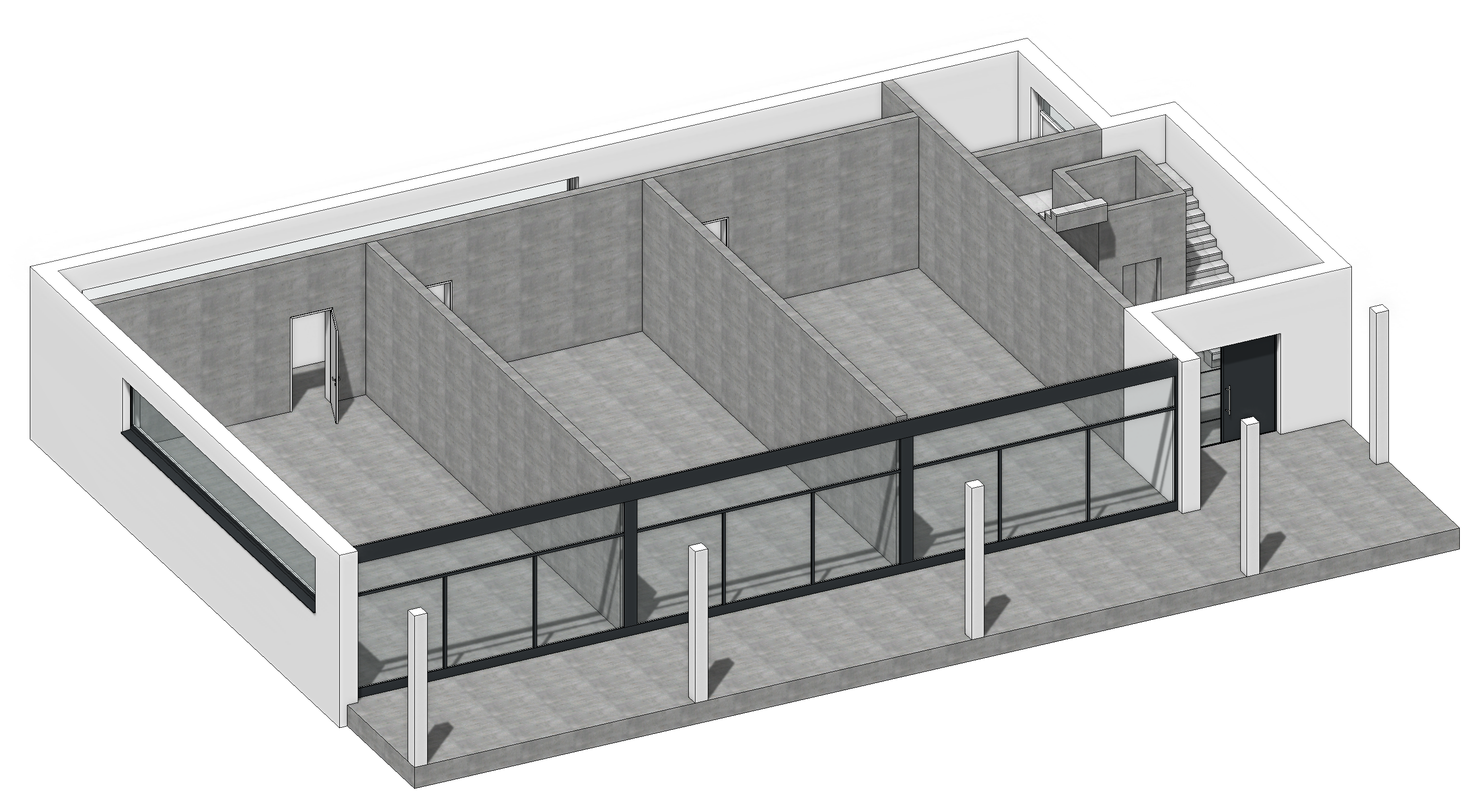
Next, we will show the GF alone and select the outer wall.
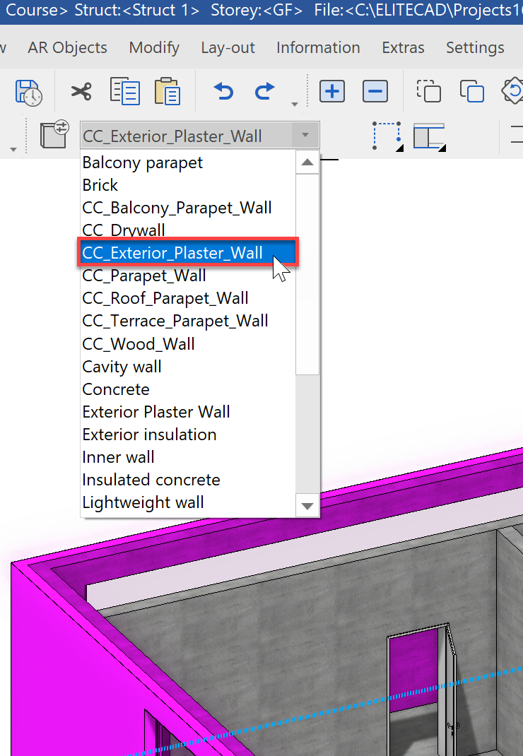
Select the data record CC_Exterior_Plaster_Wall in the property bar.
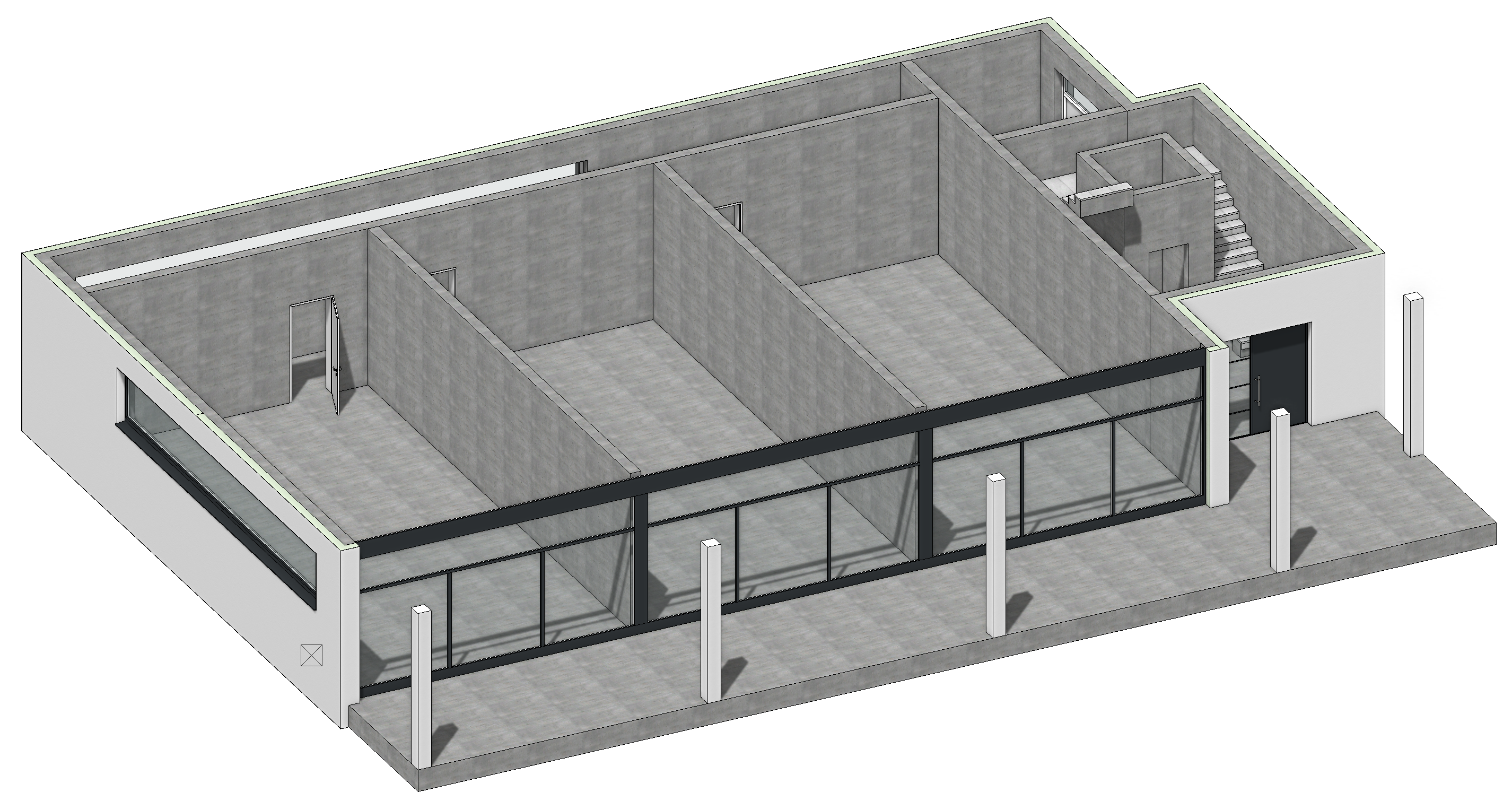
The wall assembly modifies itself immediately and we also see the resultant layers.
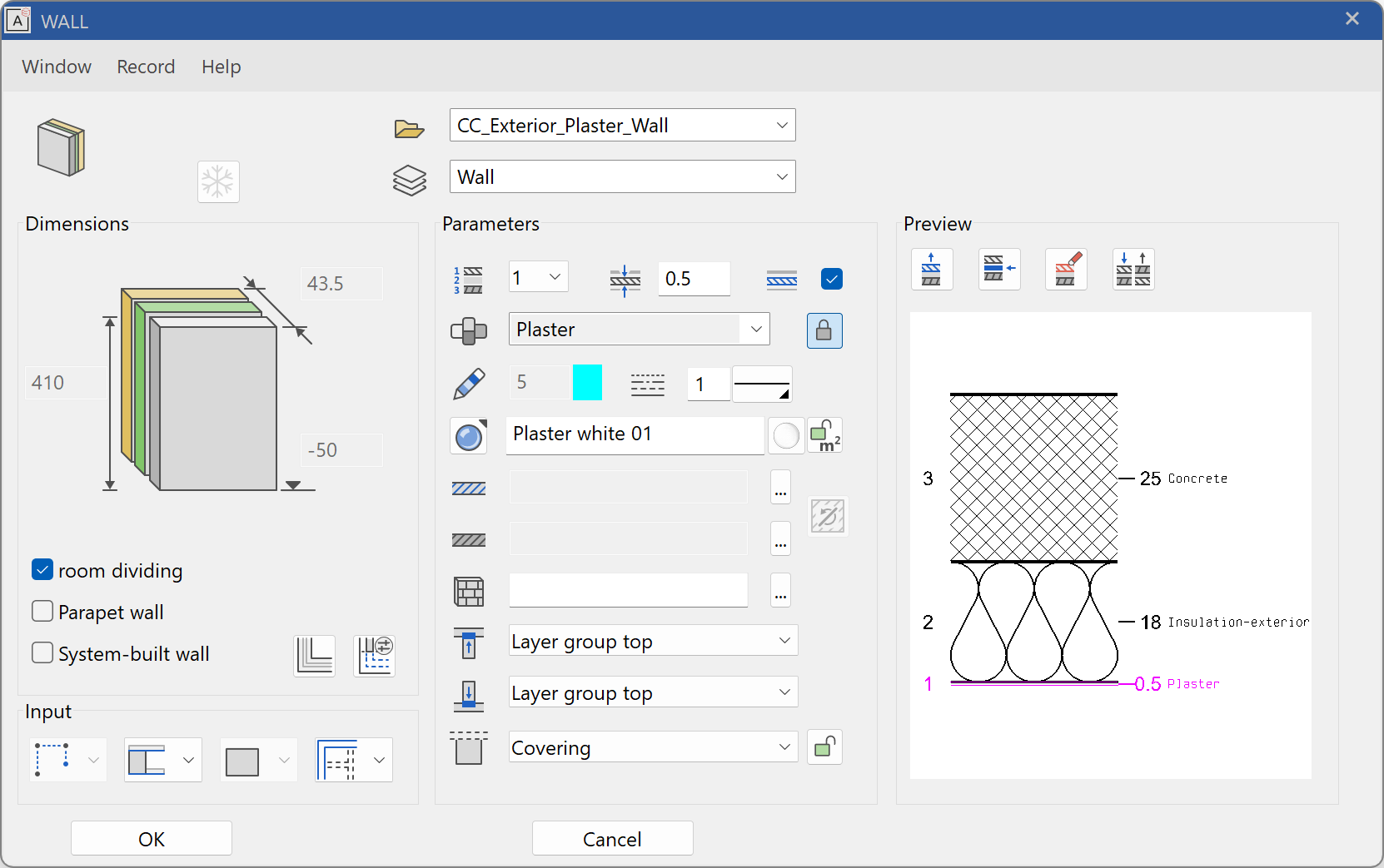
Wall assemblies are completely configurable in ELITECAD. In addition to the number of layers, you can configure the thickness, material, and intersection for each layer. A double click on the wall show the assembly. Here, you can also define you own wall composition and build templates for your projects.
We now want to copy the modified wall assembly to other walls. We can either select individual walls to change or use the now familiar function Copy parameters.
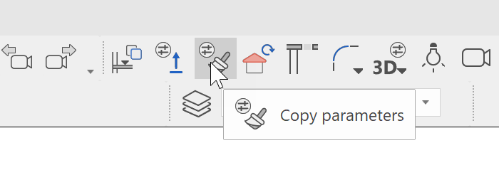
With this function, we can copy the properties of the currently selected object to other objects. In our case, we only want to copy the layer composition. First, deactivate all parameters with the switch in the bottom left. Then activate the parameter Layering and copy the parameters using the single button to the other objects.
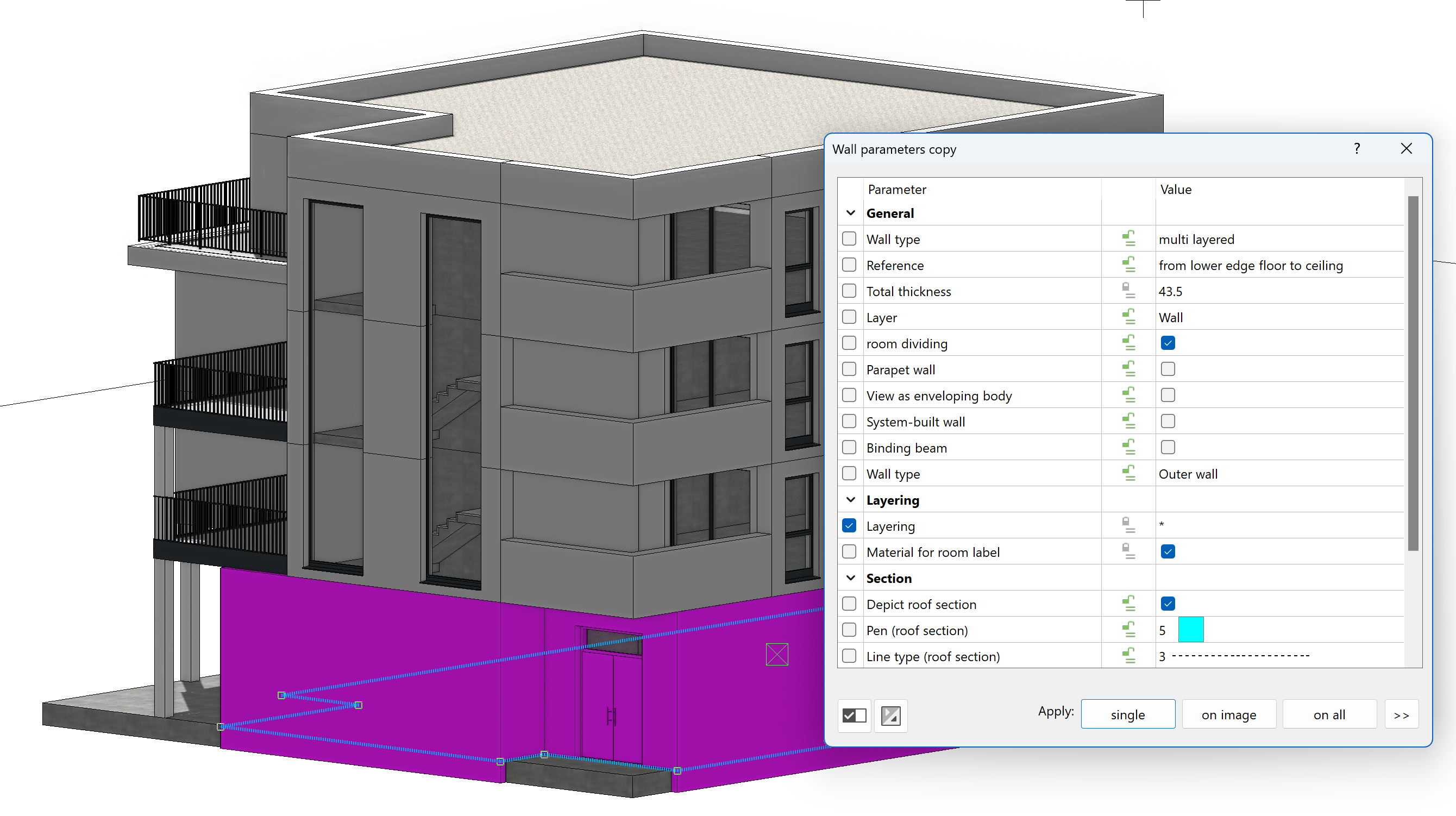
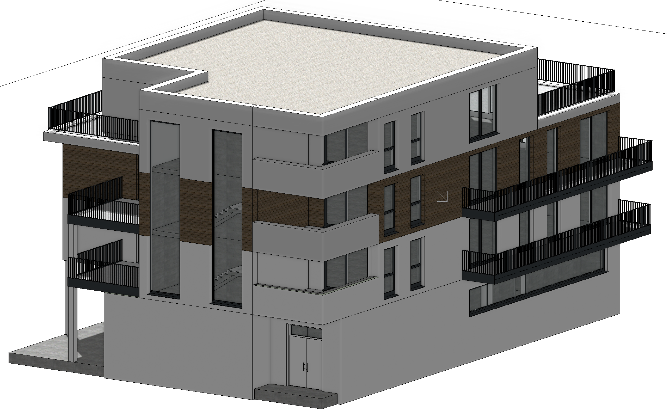
Now select the outer walls of NF1 including the parapet wall:
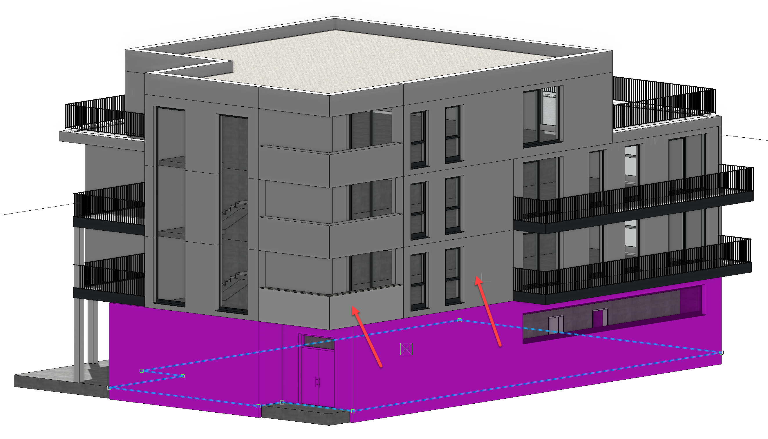
In the upper storeys, wooden slats as an eye-catcher are to be built. To this end, select a wall on the second storey and change this to the data record CC_Wood_Wall.
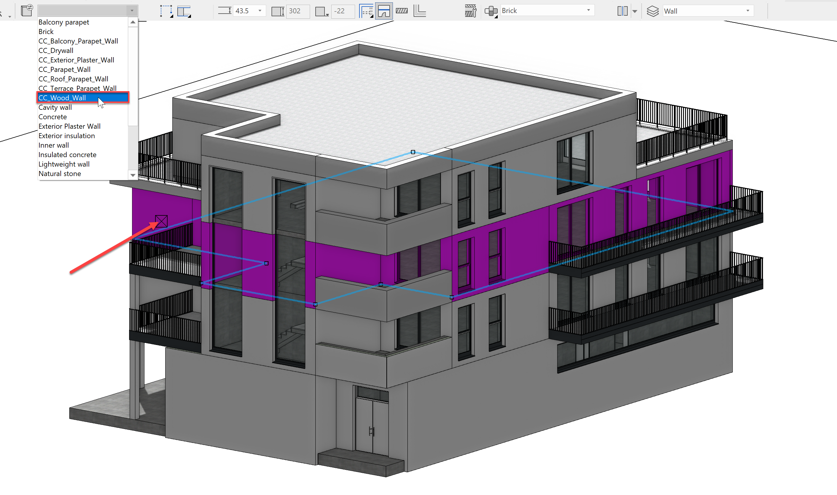
The result should look like this:
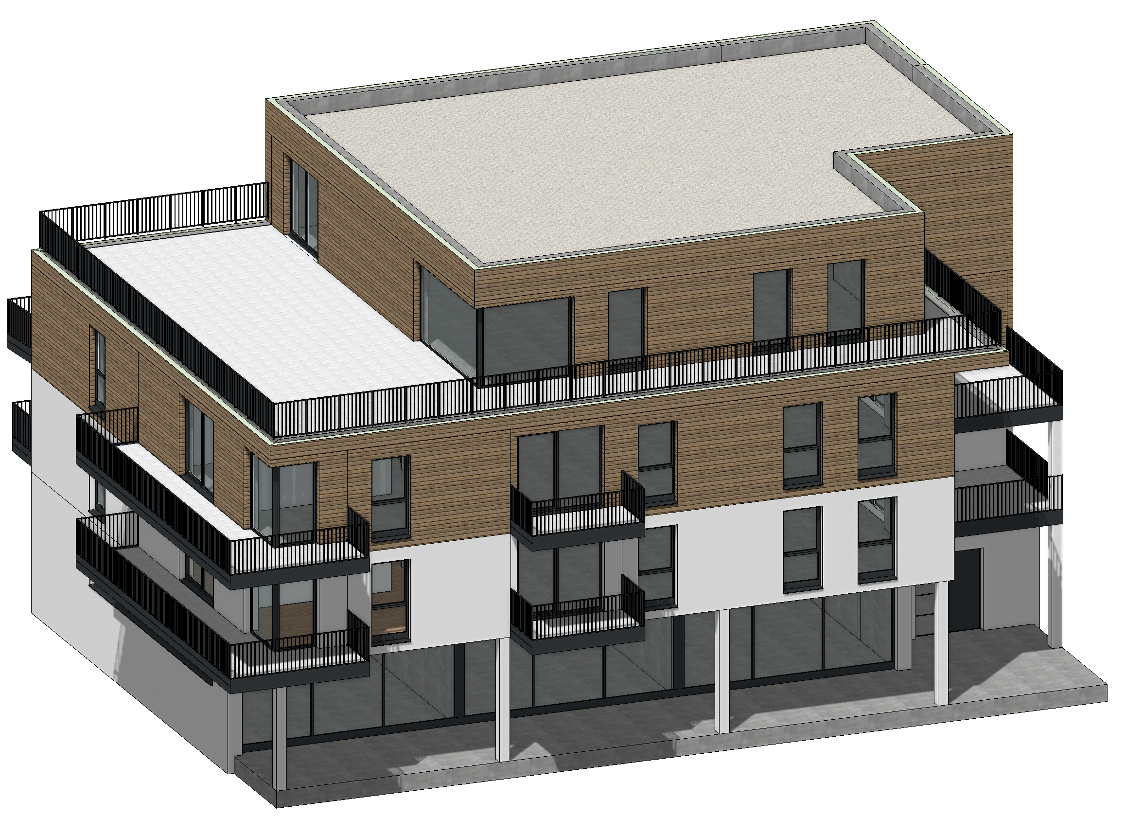
Now use the function Copy parameters again to transfer the layer structure of the wooden slat wall to the remaining walls including the parapet walls of NF2 and TF1. Your building should now look like this:
With this, the wall assemblies of the building have not been completely adjusted. In the next section, we will see how to set the model in an attractive setting.