Rooms
Adjusting the stairwell
Before we begin the rooms, we must correct a smaller detail. The slabs in the stairwell must be adjusted to the stairs. To begin, show the first floor alone and select the contour of the slab. Using the function Reduce polygon from the input assistant, you can modify the contour.
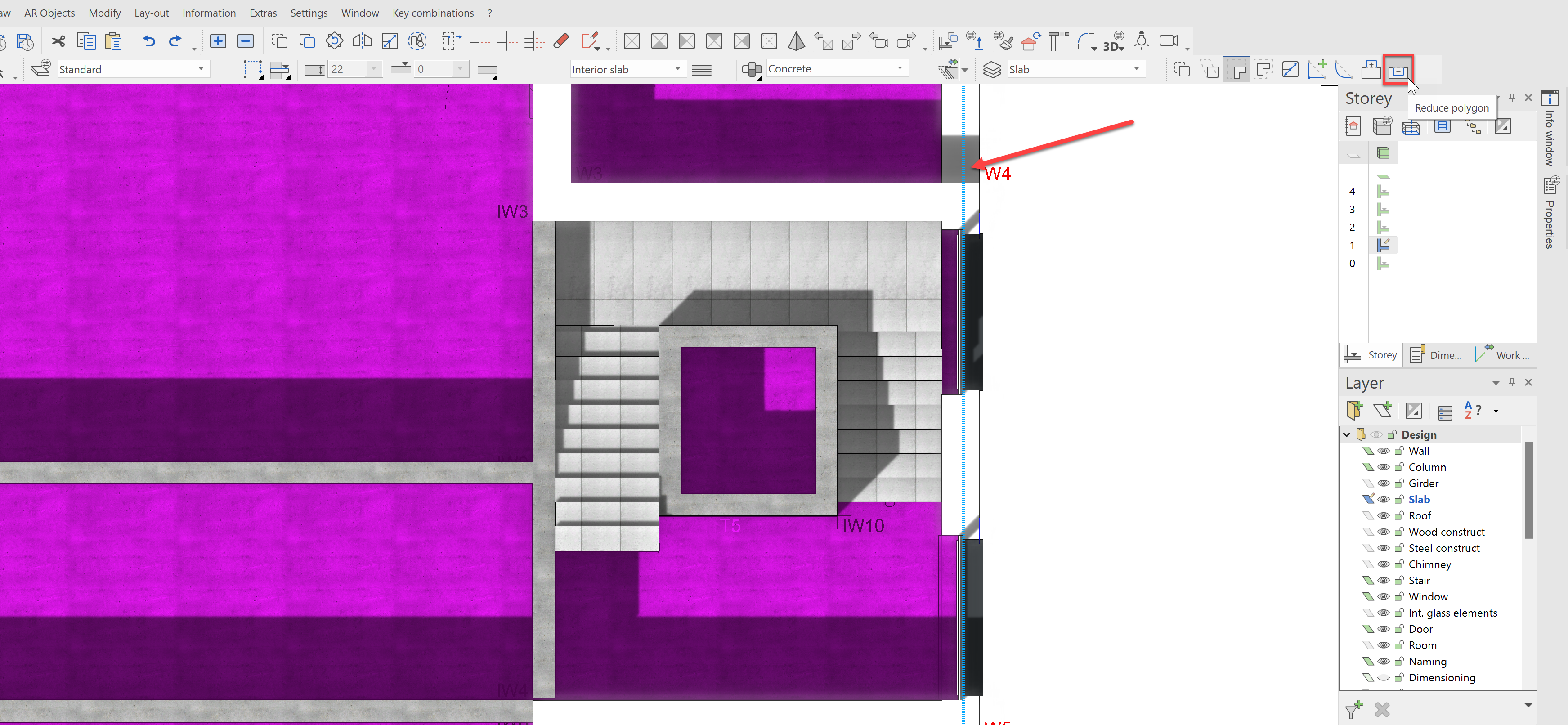
Adjust the contour as shown below:
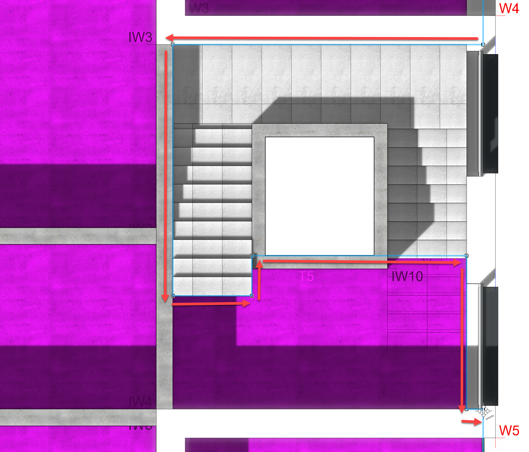
The stairwell and the elevator shaft should be removed. Repeat this process for the other storeys.
Depending, whether you correctly set the height reference of the elevator shaft or not, you may not need to correct anything. In opposition to the other walls, the elevator shaft walls go from slab underside edge to the underside edge of the slab above. If you have a gap between the walls, as shown in the screenshot, you will have to correct the height reference.
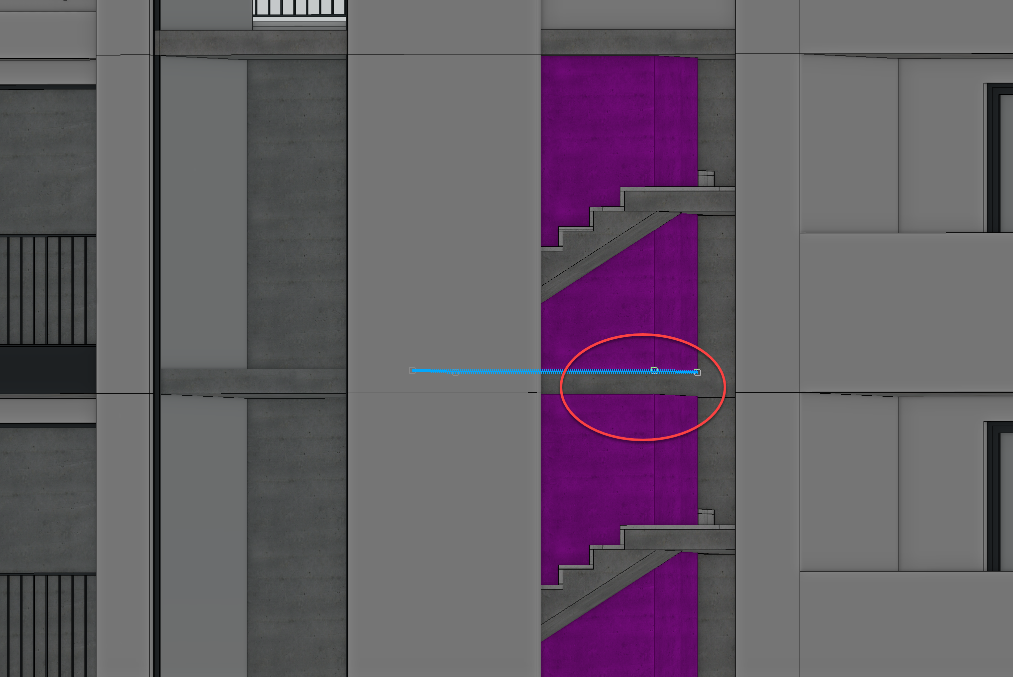
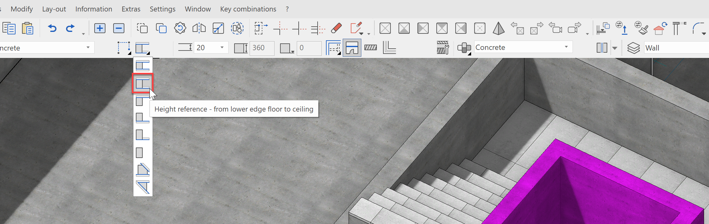
If a gap is visible, change the height reference to from lower floor edge to ceiling.
The same correction may also be necessary in the other storeys as well.
Maybe you have noticed, that we have not copied the opening for the lift doors from the GF to the other stories. Using the Copy into active storey funtion, we will fix that now.
Rooms
Next, we want to define the interior rooms. The object Room contains a lot of information in ELITECAD. On one side, it determines the construction of (multi-layered) floors inside the room contour as well as the wall and ceiling finishings. On the other side, the room object allows for many calculations to be evaluated and displayed, such as areas, volumes, use types, labels, etc.
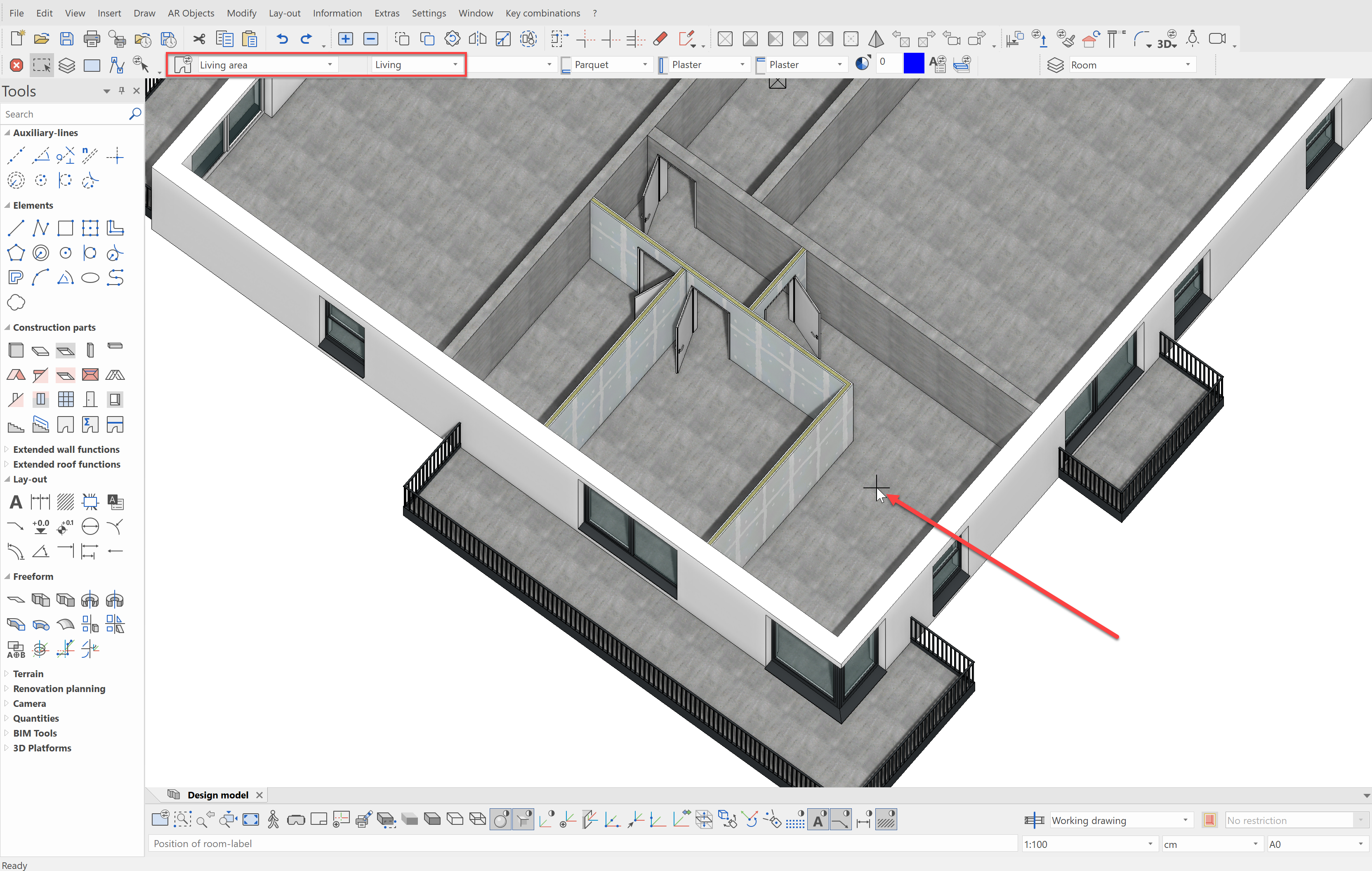
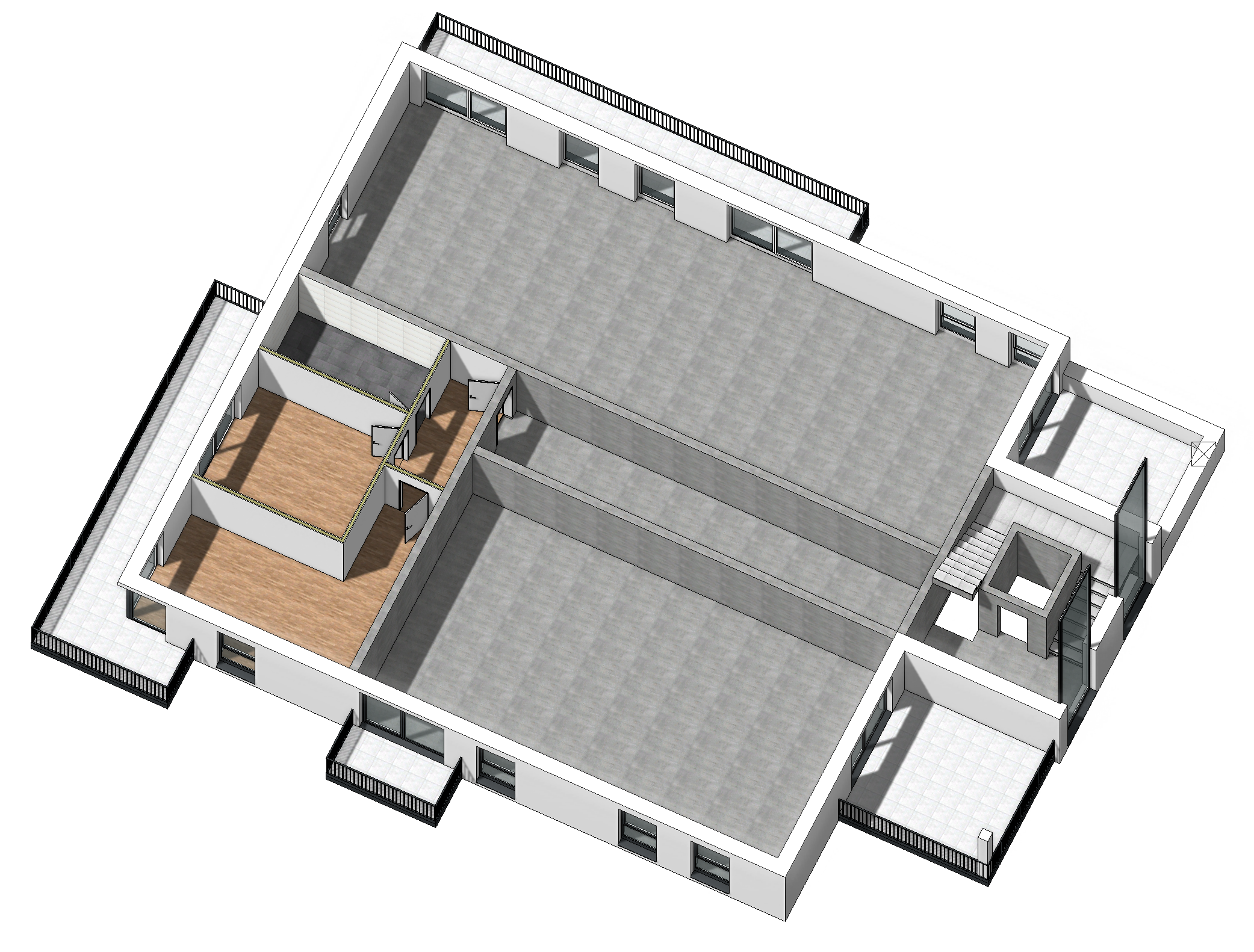
As an example, we will set the rooms for the apartment on NF1. Show the storey alone and select the construction part Room from the tools manager Construction parts.
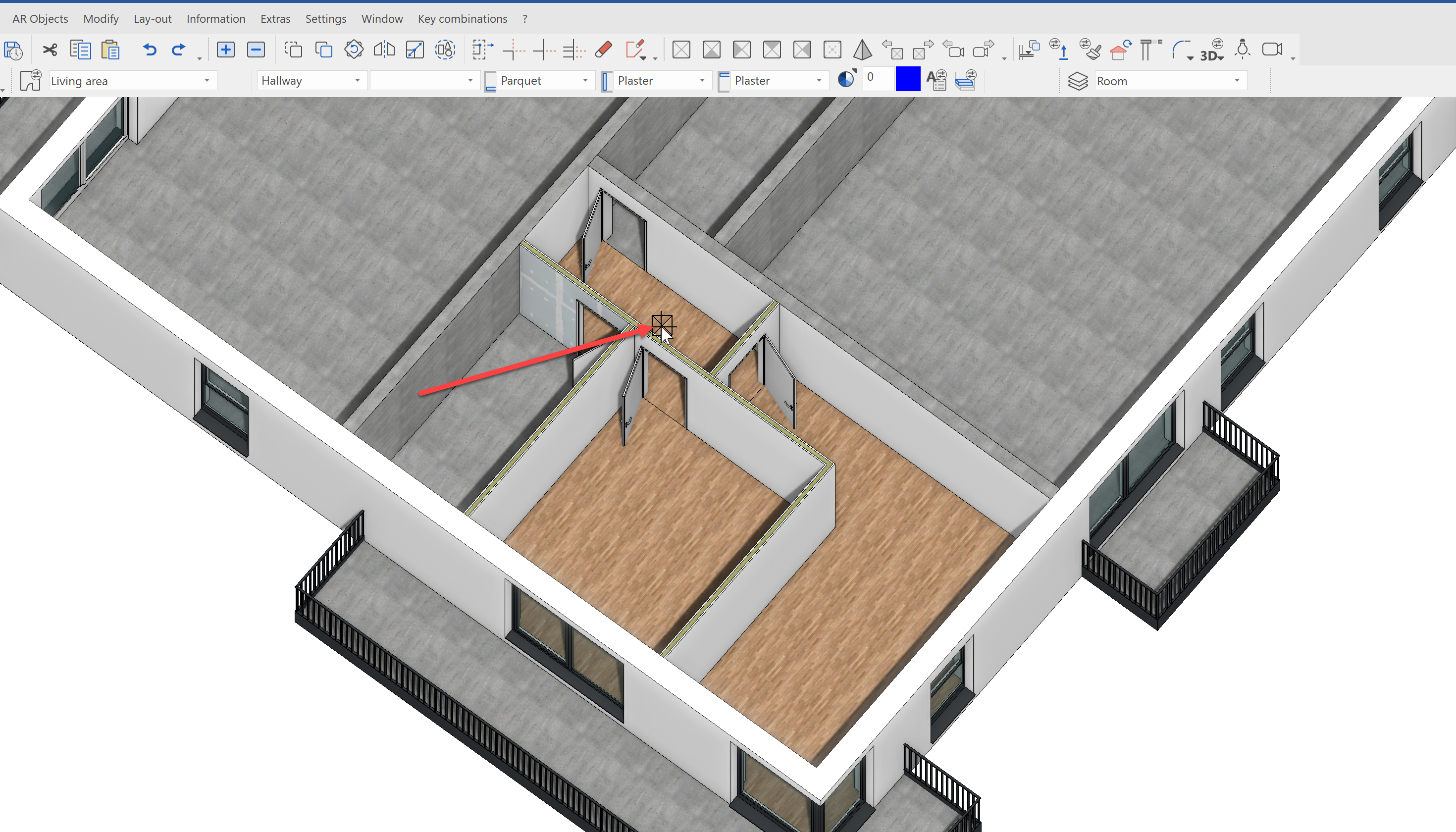
Let's start with a living room. To begin, simply click in the desired area. If the walls are all neatly drawn, the object automatically finds the boarding walls and independently determines the room contour. The position of the clicks determines the position of the room labelling for the 2D plan.
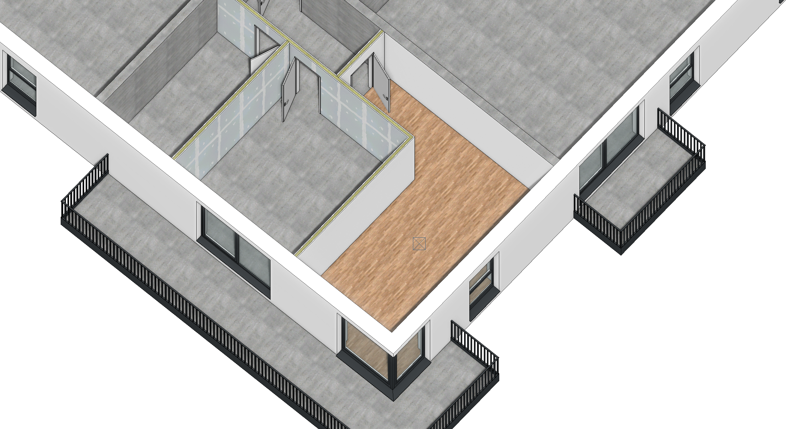
The results are immediately visible. According to the preset properties such as floor structure with insulation, screed and parquet, as well as white plaster on the walls, the room is created with just one click.
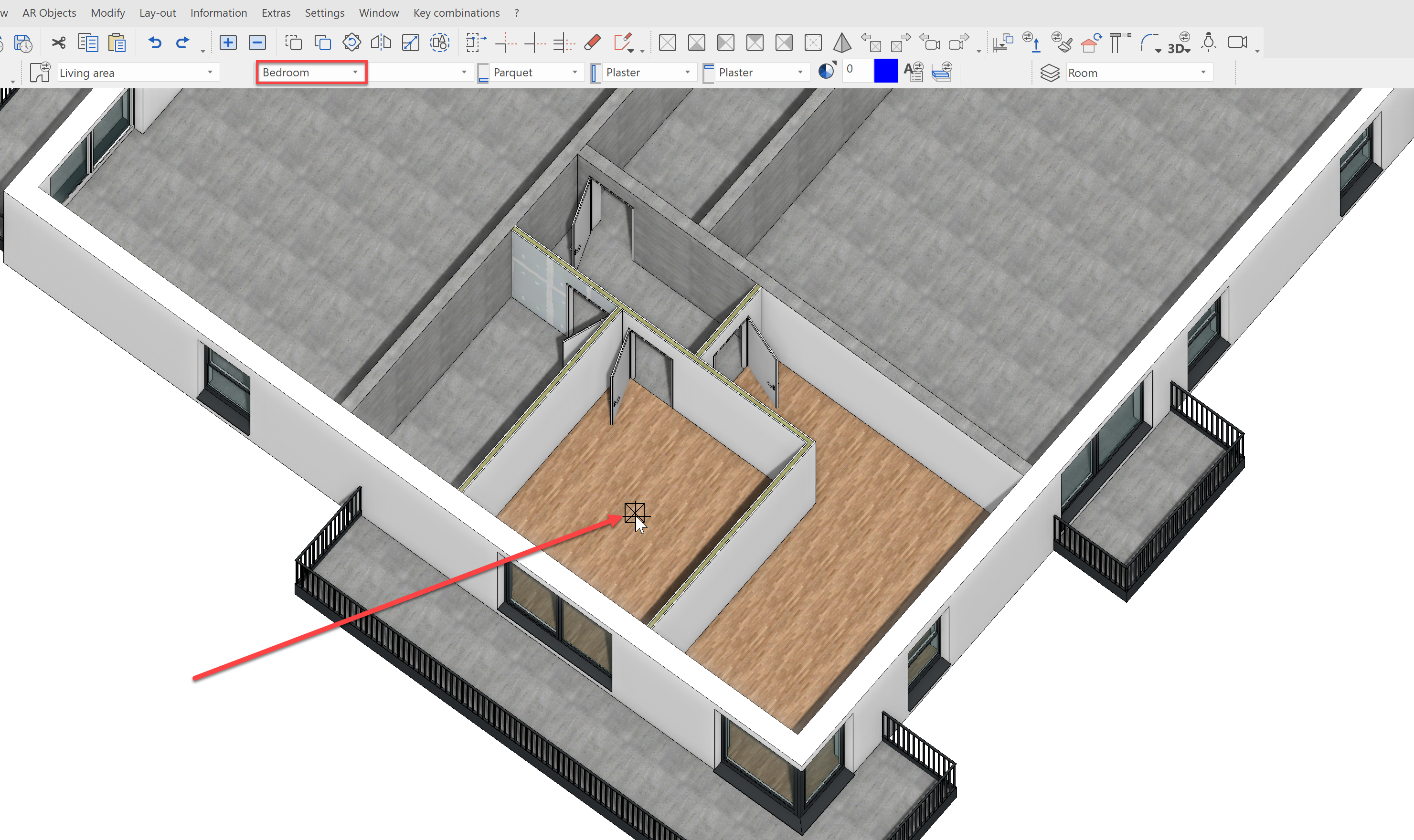
Next, we will define the bedroom. Here, we change the usage category in the property bar to Bedroom. This information will be shown later in the 2D plan. Click in the room to set it as a bedroom.
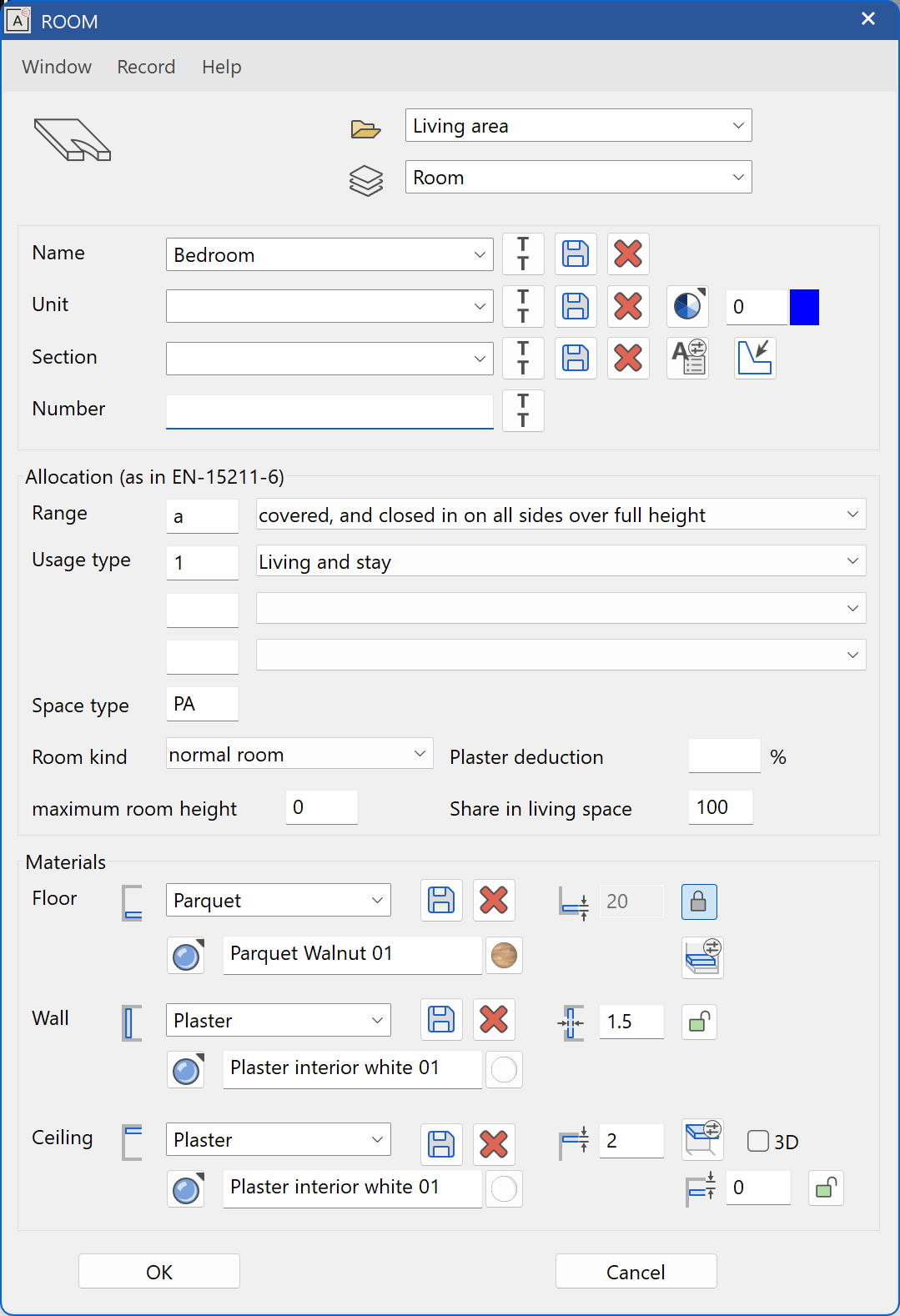
The settings of the room can, of course, be adjusted at any time. The parameter menu for the room can be opened with either a double click on the room or from the property bar. Here, we already see numerous settings that can be adjusted, such as the coverings, how the areas should be calculated, what information should be displayed in the 2D plan, etc.
Up next is to define a room as a hallway, by changing the usage category to Hallway and clicking in the desired room.
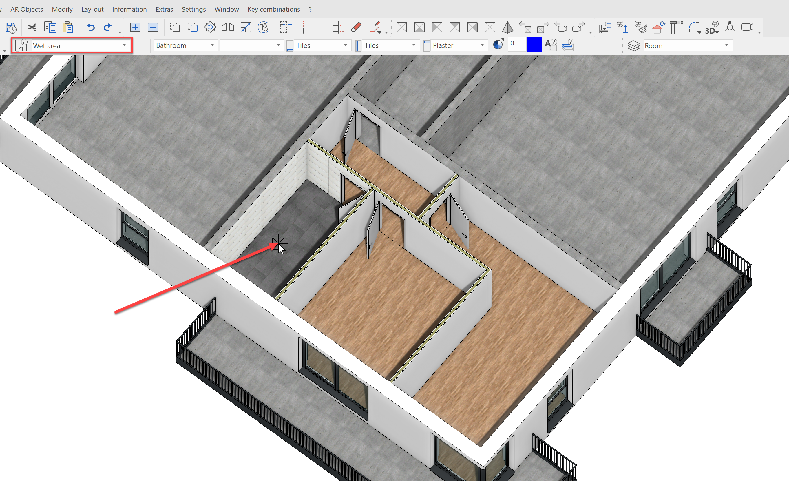
Our final interior room to define is the bathroom. For this, we will select the data record Wet area and the usage category to Bathroom then clicking in the desired room.
Even outside, rooms play an important role. Using rooms, you can, for example, regulate the floor assembly of terraces or flat roofs.
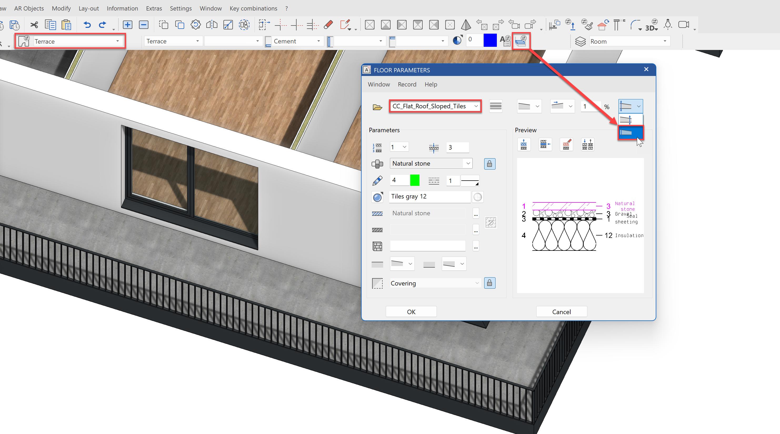
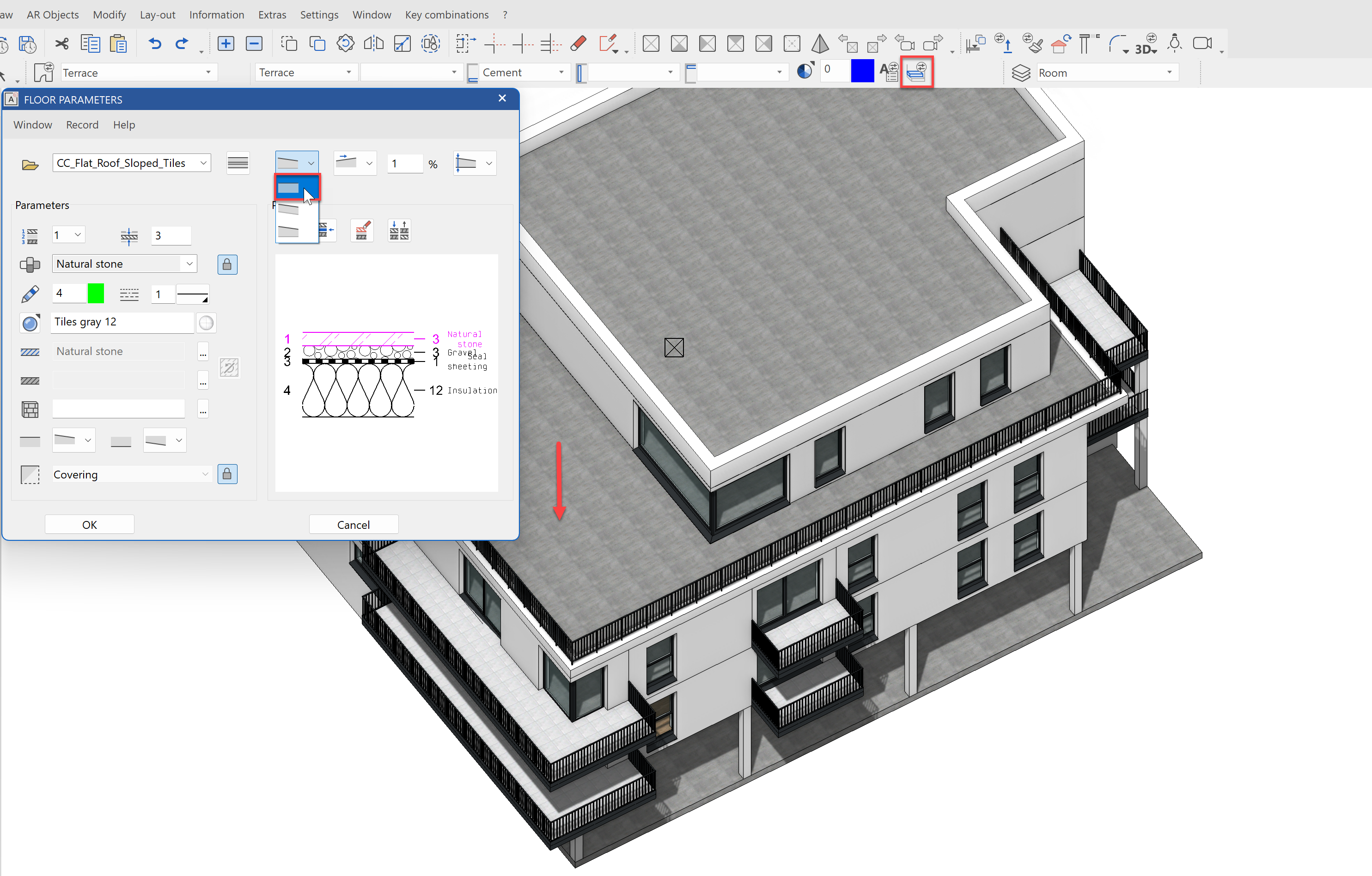
As an example, we will place a room with the data record Terrace. Before we define the room object, we will change the floor assembly. To do this, open the dialog Floor assembly from the room property bar Select the data record CC_Flat_Roof_Sloped_Tiles. Here, we also see the individual layers of the floor, from the insulation to the panels. Set the layer thickness to the maximum value as specified and confirm the dialog with OK.
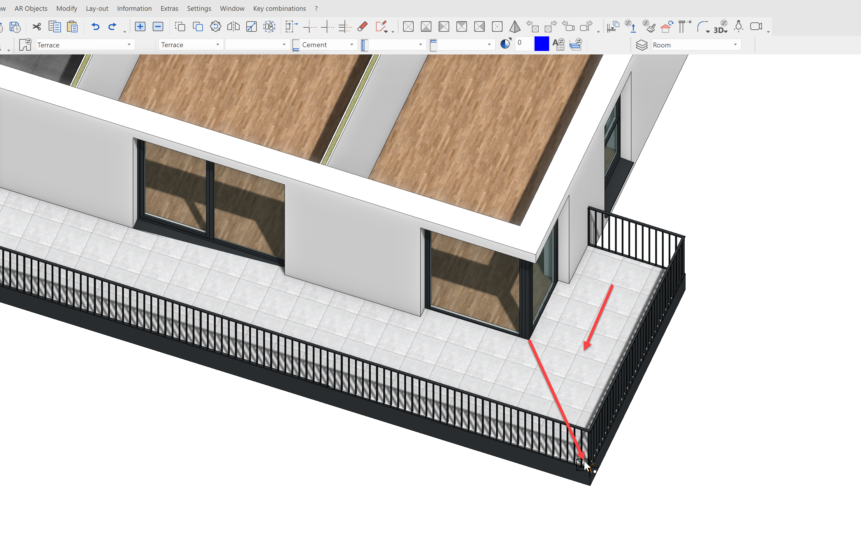
To be able to define the room, first click on the terrace, so that the room contour gets defined. After that, the direction of the incline must be indicated. The first point, i.e. the Upper edge should be up against the facade. The second point indicates the direction and should be placed in the corner of the terrace.
Finish the remaining terraces in a similar fashion and copy them in to NF2.
For the sake of simplicity, we will define the TF1 terrace without an incline. For that, change the following setting in the floor assembly and then click on the terrace.
The result should look like this:
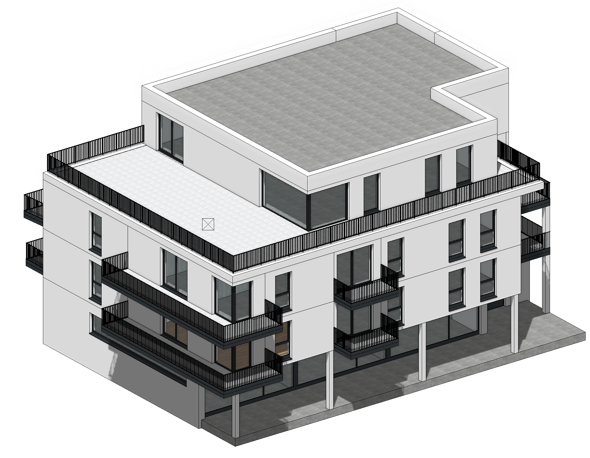
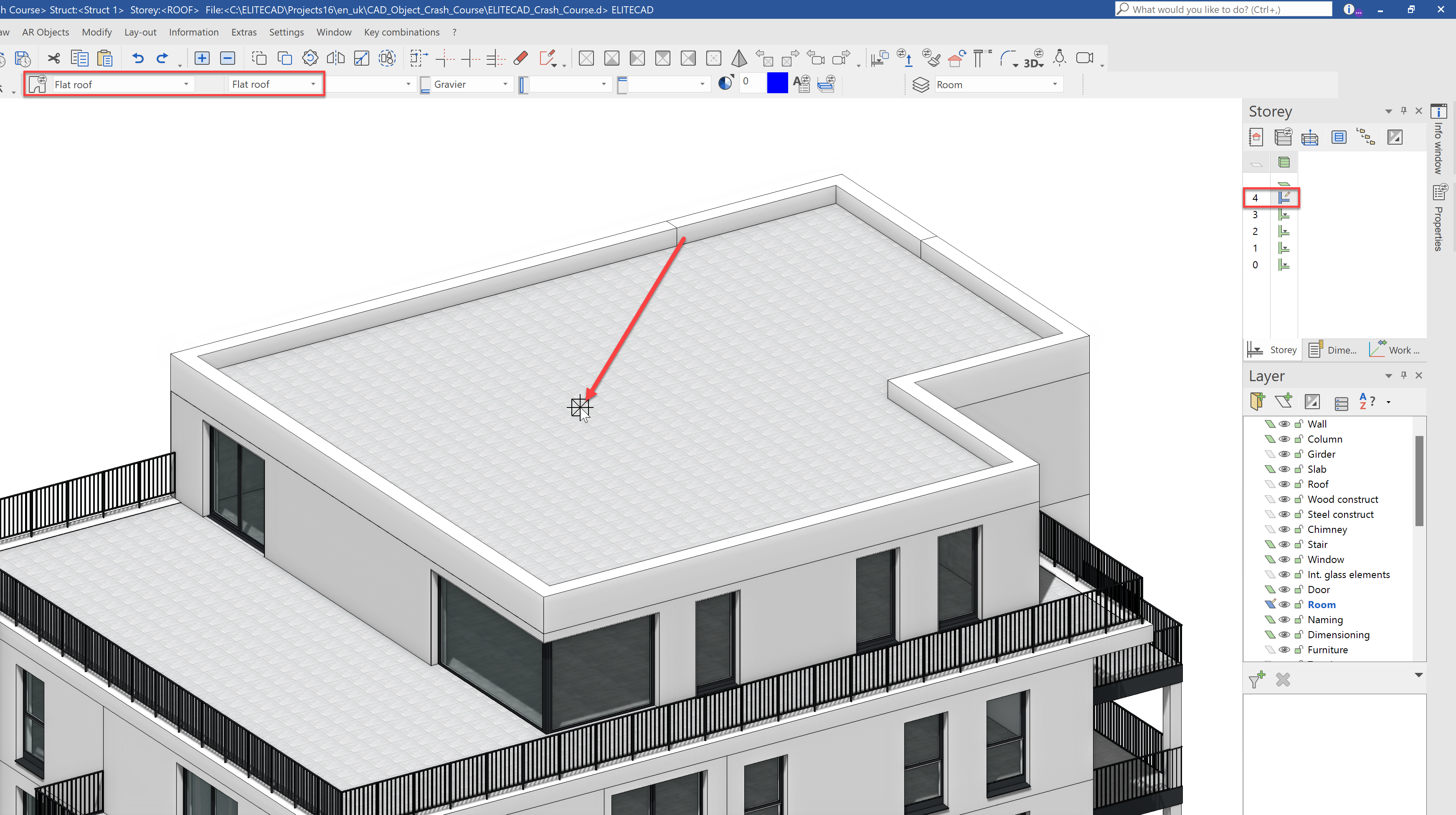
Finally, we will define the flat roof. Activate the storey Roof and select the data reference Flat_roof. With a single click on the roof, the multi-layered roof assembly will be created.
Our finished building model now looks like this.
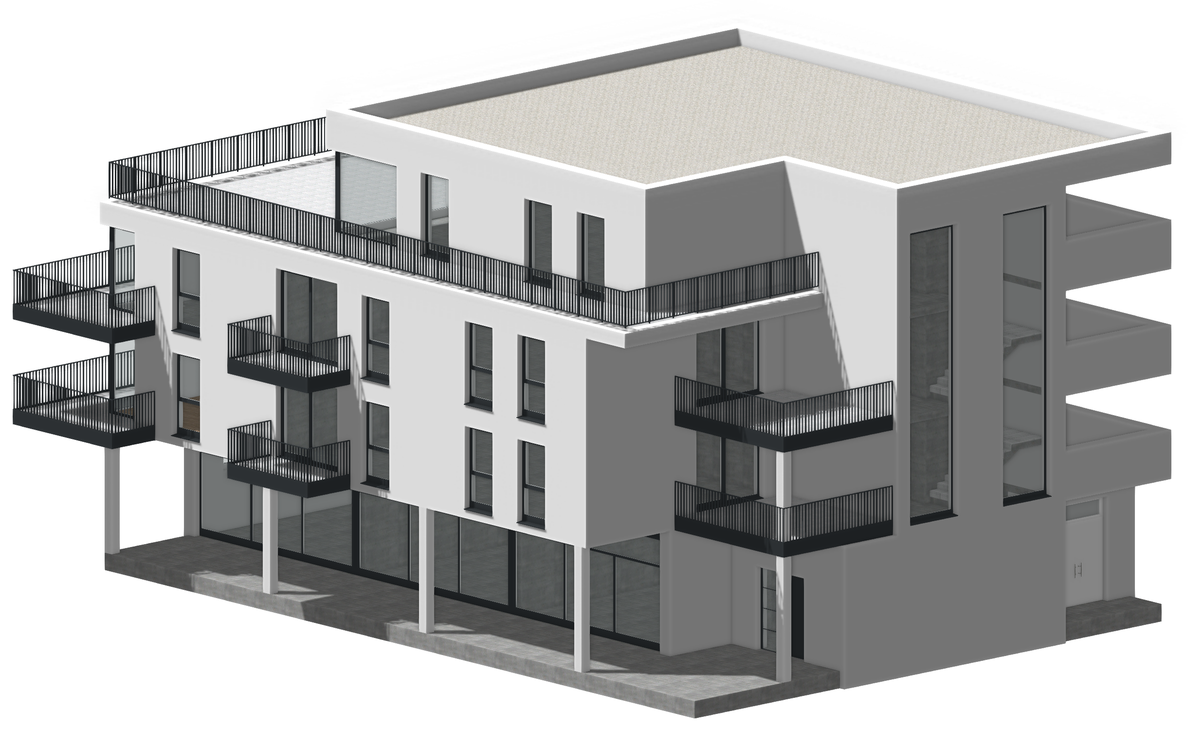
You are free to define other rooms as you would like.