Plan formatting and PDF export.
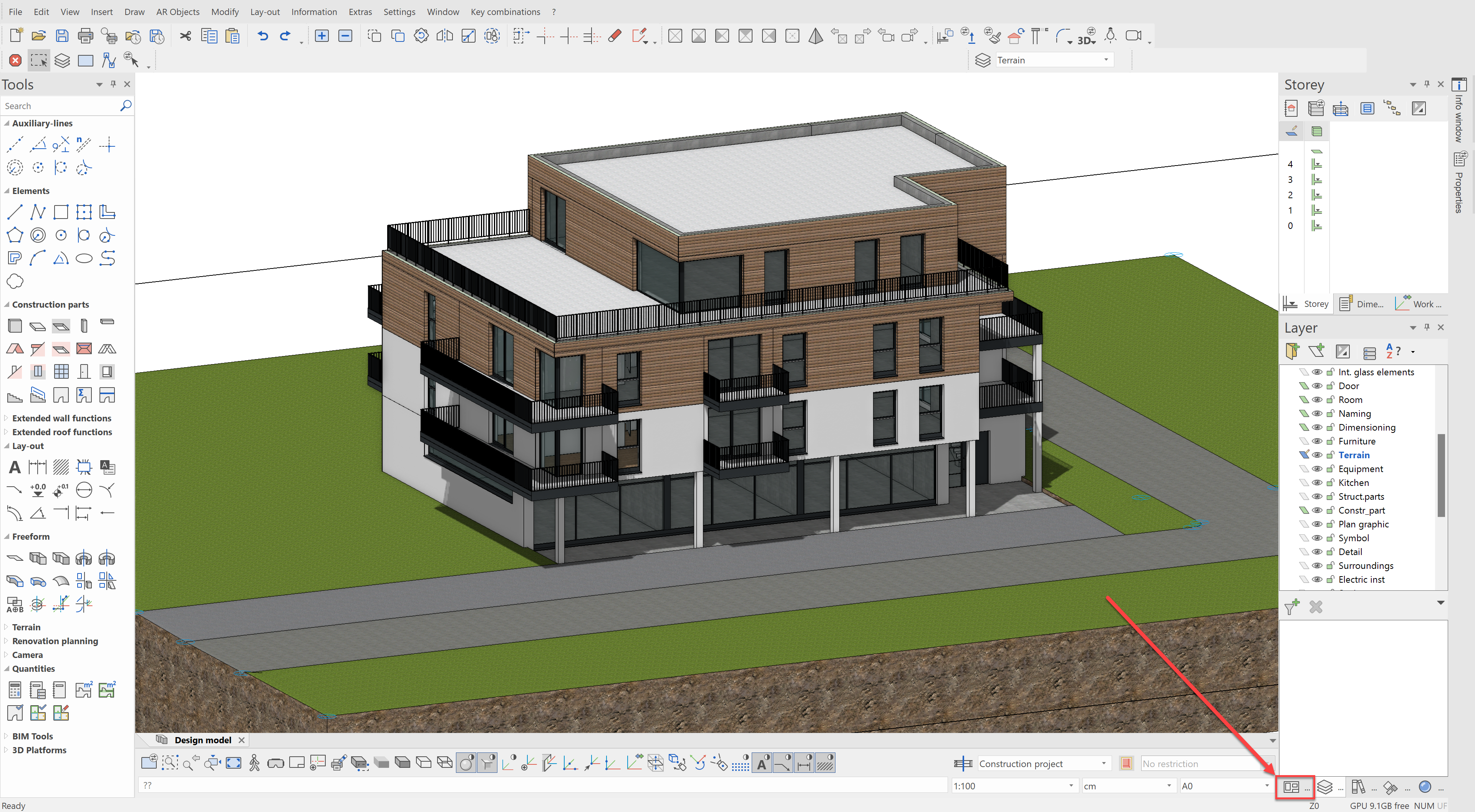
The 3D building model is now completely modeled. In the next step, we will create our matching 2D plans like the floor plans, views and sections. As we are working with a project template, these are already predefined and must only be refreshed and filled out as desired.
Refresh plots
Firstly, we want to update the plots that we looked at in the first chapter. For this, open the views manager:
The individual views and floor plans will be skipped here. Let's go straight to the assembly pf the plot. Open the first plot with the name Floor plans:
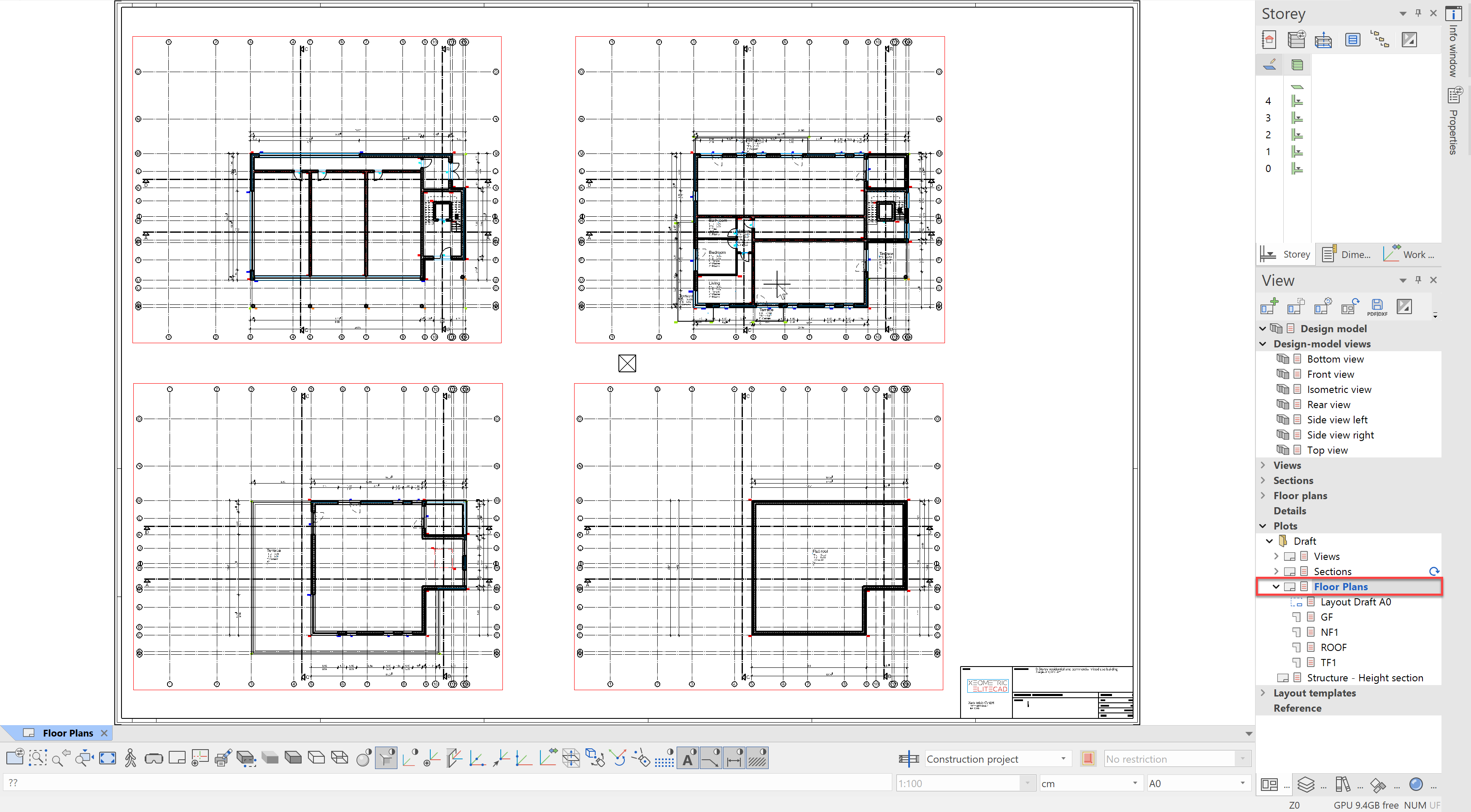
We see here that everything is already up-to-date and, thanks to project templates, even has the title block complete with our own corporate design.
Open the plot Views next
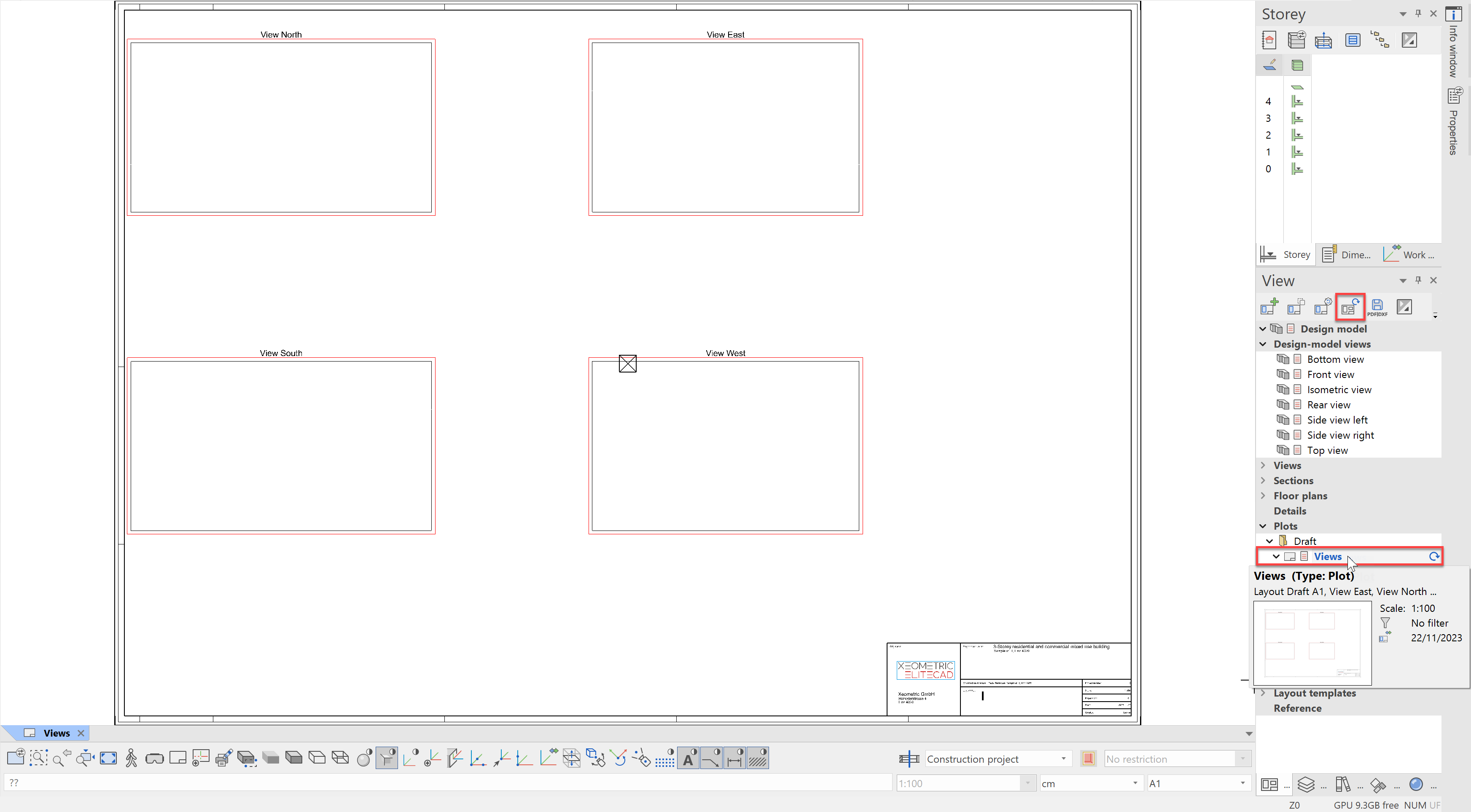
The plot view may be empty, since views are only recalculated manually for performance reasons. If a view is not current, this is indicated with a symbol next to the affected view/plot/etc... To fix this, click on Refresh view either in the header for the views manager or to the right next to the plot name to be updated. All views, which are used in the plot, are updated.
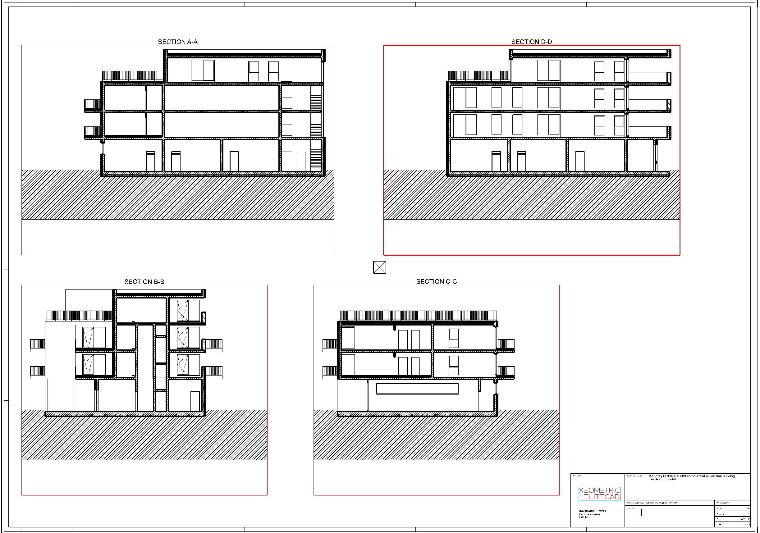
After a few seconds, the plot should look like this:
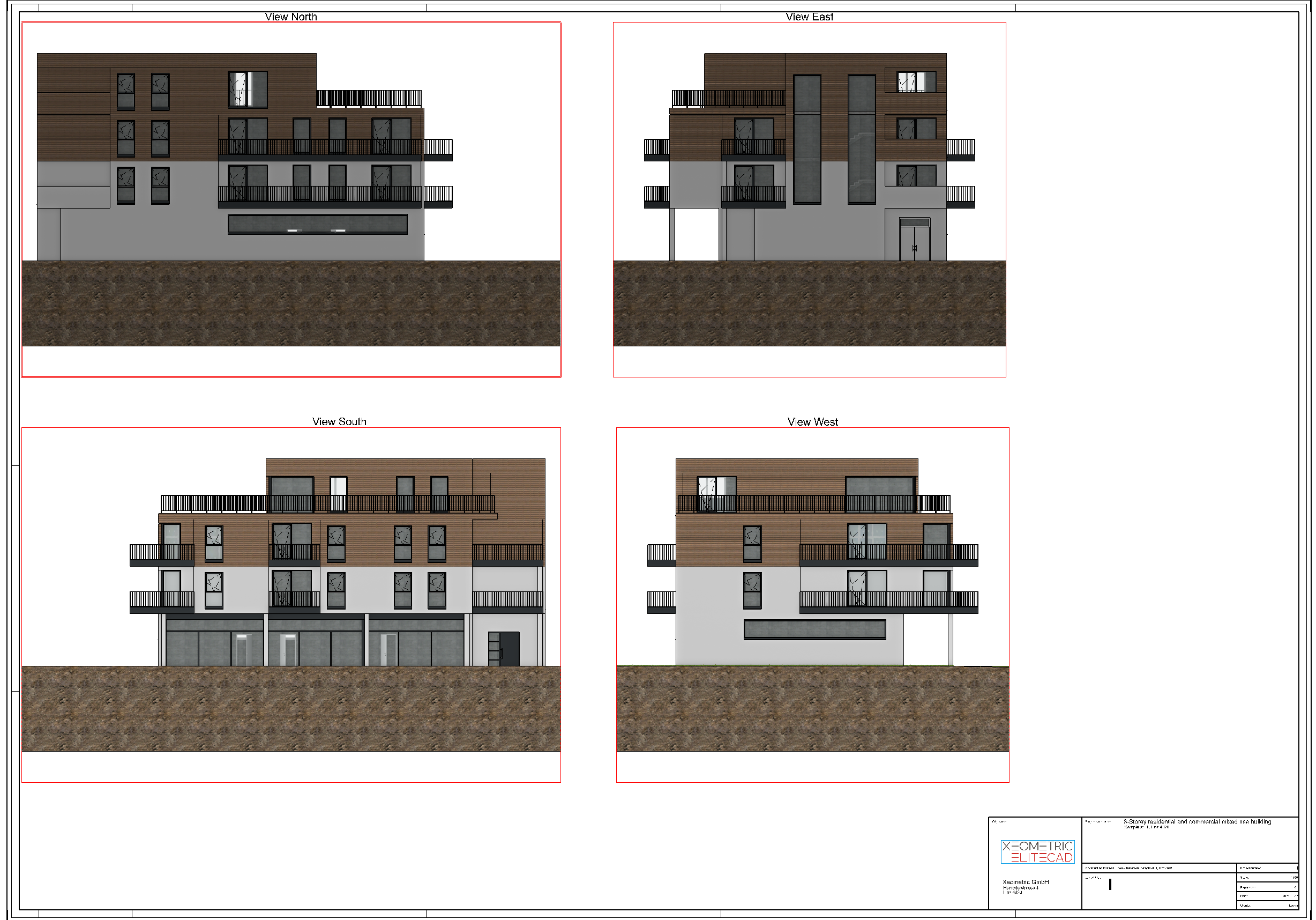
The plot Views is shown in the solid depiction. This could just as easily be defined as a hidden line view.
Open and refresh the plot Sections* next.
Section formatting
The plots are naturally true to scale, but they are lacking in references and dimensions. Of course, the resulting 2D plans can be expanded with this information. Let's see on an example of a section, how easy this works in ELITECAD.
Room labelling
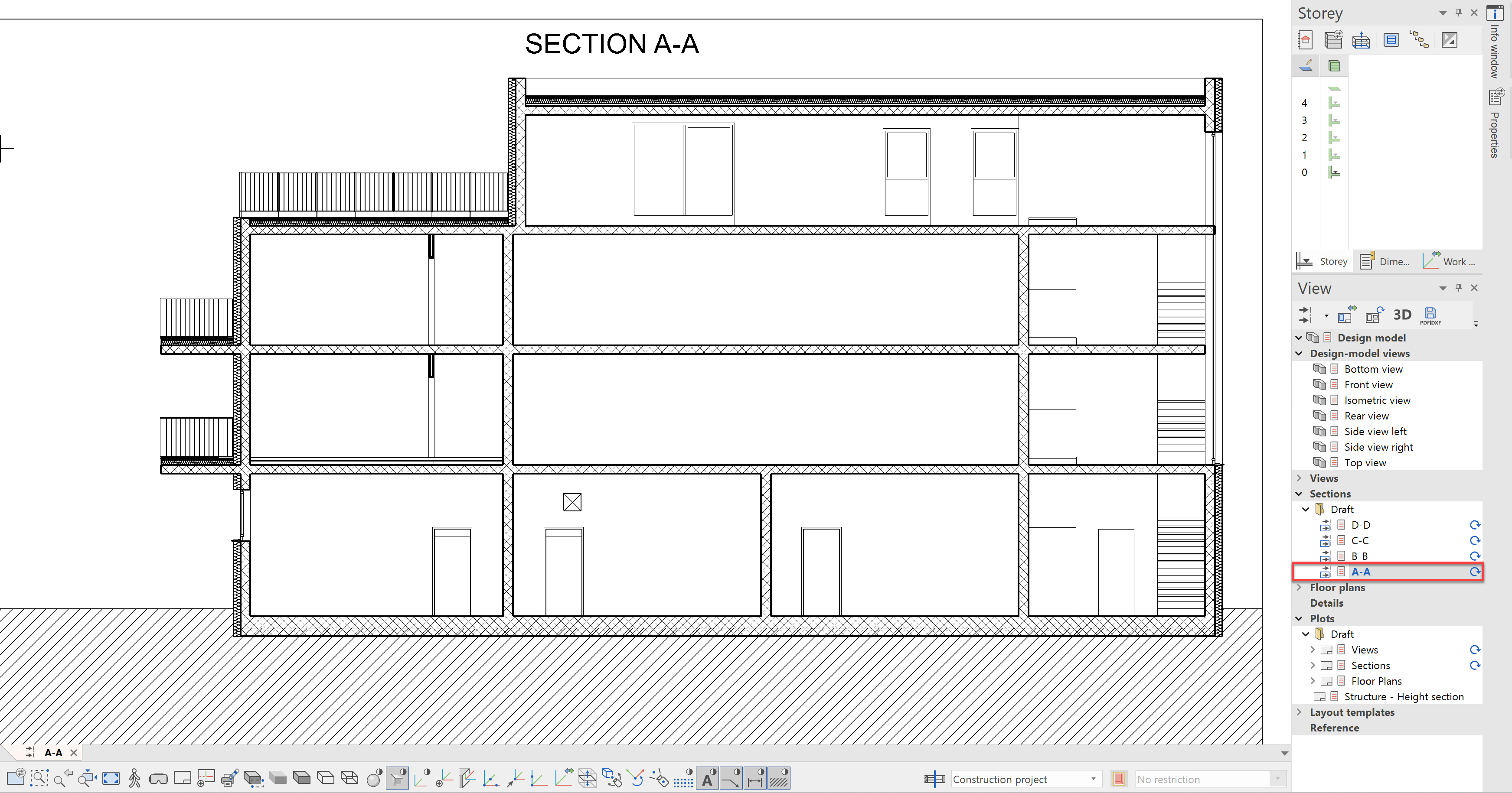
Open the section A-A from the tab Sections->Draft in the views manager:
This should now be expanded to include labels for the rooms. To do this, select the object Attribute label from the tools manager and the data record, Room Label for Section in the property bar:
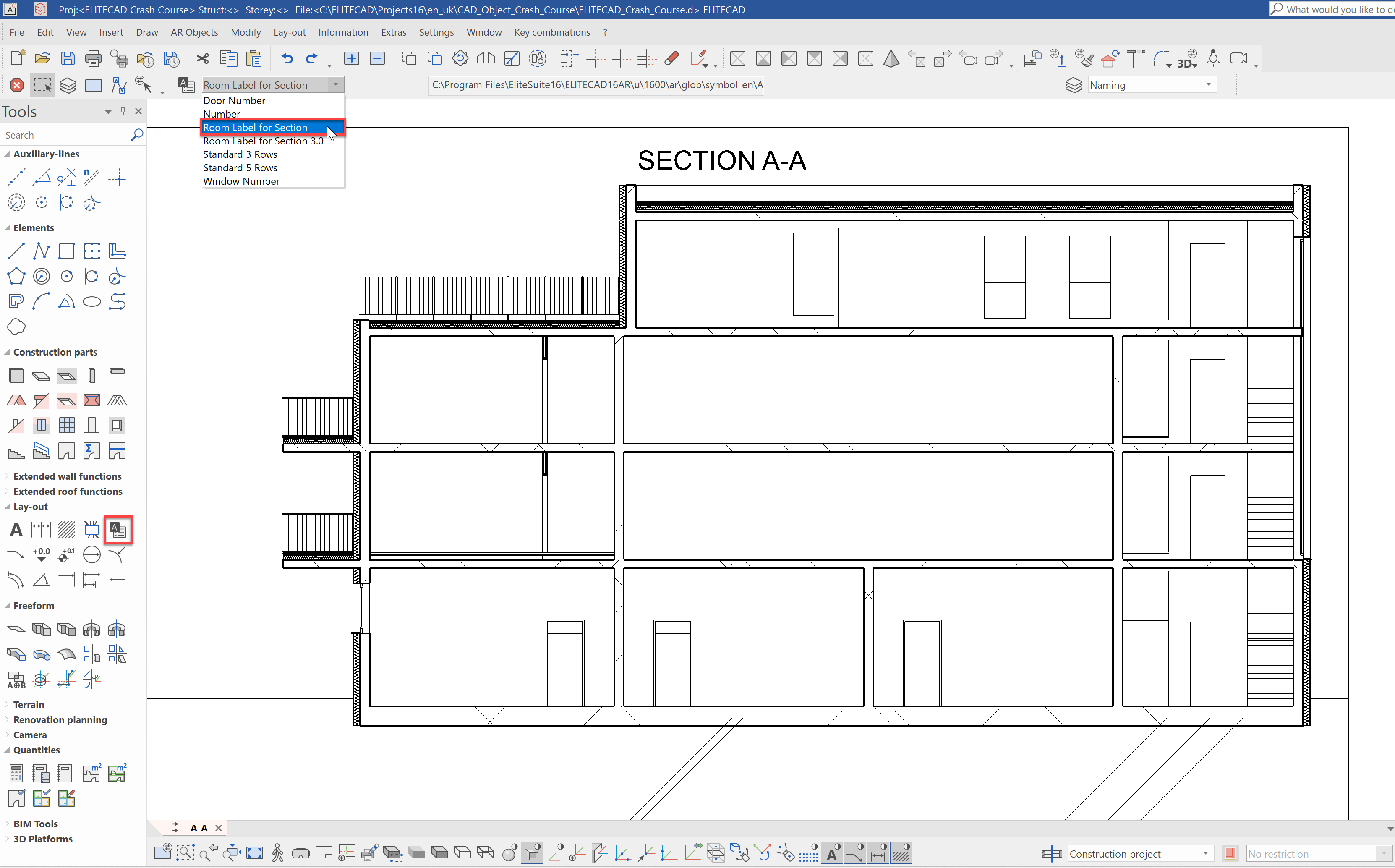
Click on the floor covering of a room that you already created, e.g. First storey bathroom. Make sure that it is the floor covering that was really captured, otherwise the information cannot be determined from the room object. The first click selects the room and the second click indicates the position of the label.
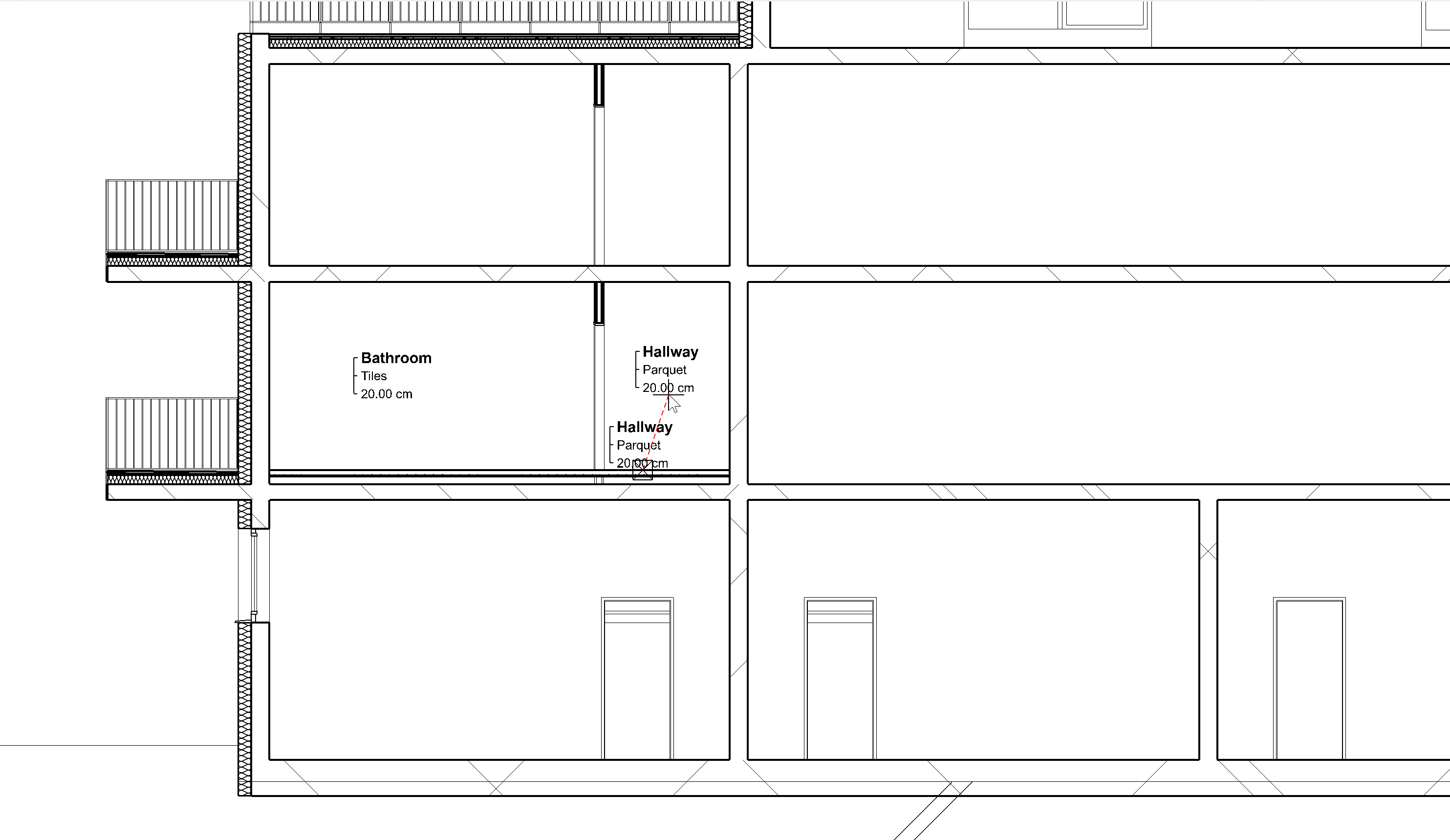
The result could look like this:
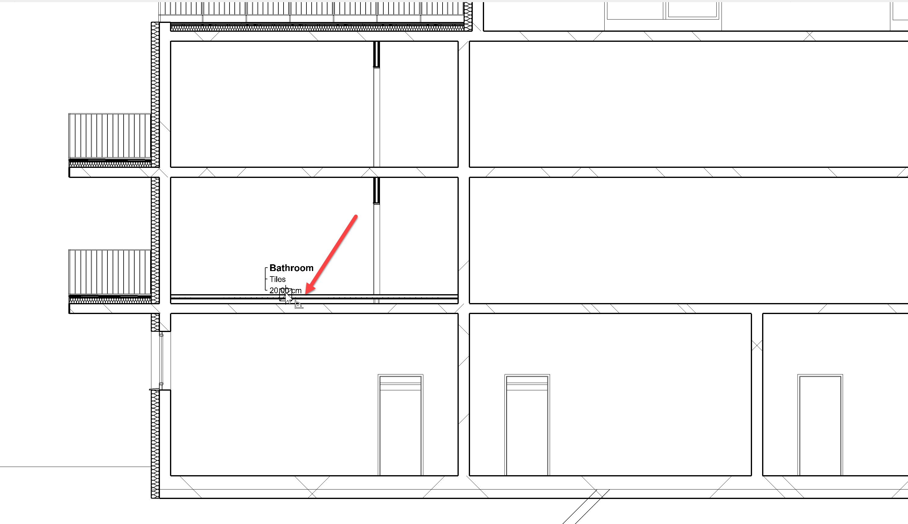
It is currently configured so that the room name, the flooring and the thickness of the floor structure are displayed. The information shown can be expanded or changed as needed. The big advantage of the room label compared to conventional text labels is that it automatically updates when changes are made to the building model. If, for example, the floor assembly changes, ELITECAD automatically adapts the label to the new height or the covering.
Label the other rooms as you choose, e.g. the hallway:
Height markers
Next, we want to define height markers in reference to the project null. To start with, the bare slab should be labelled on the top and bottom side.
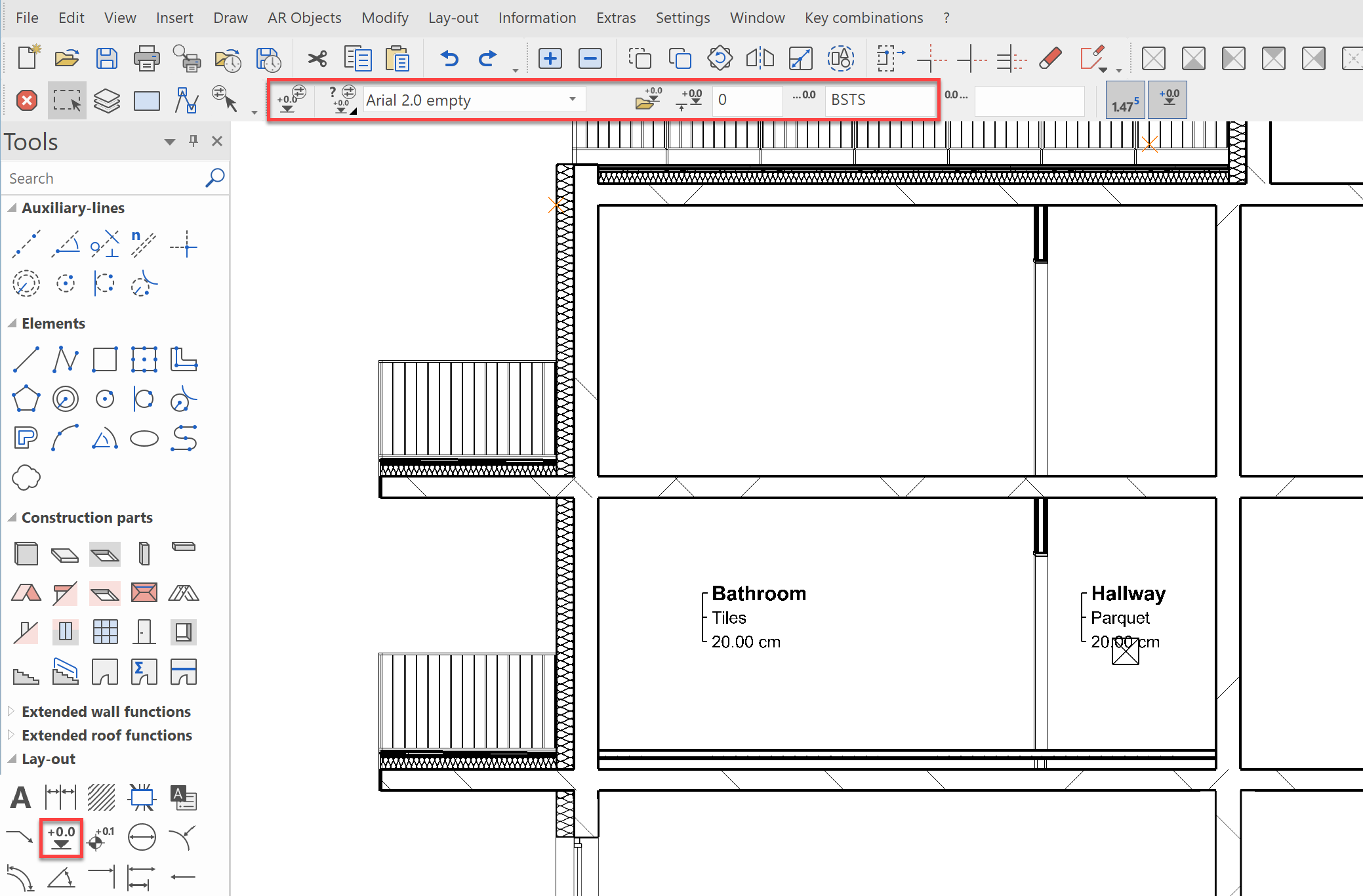
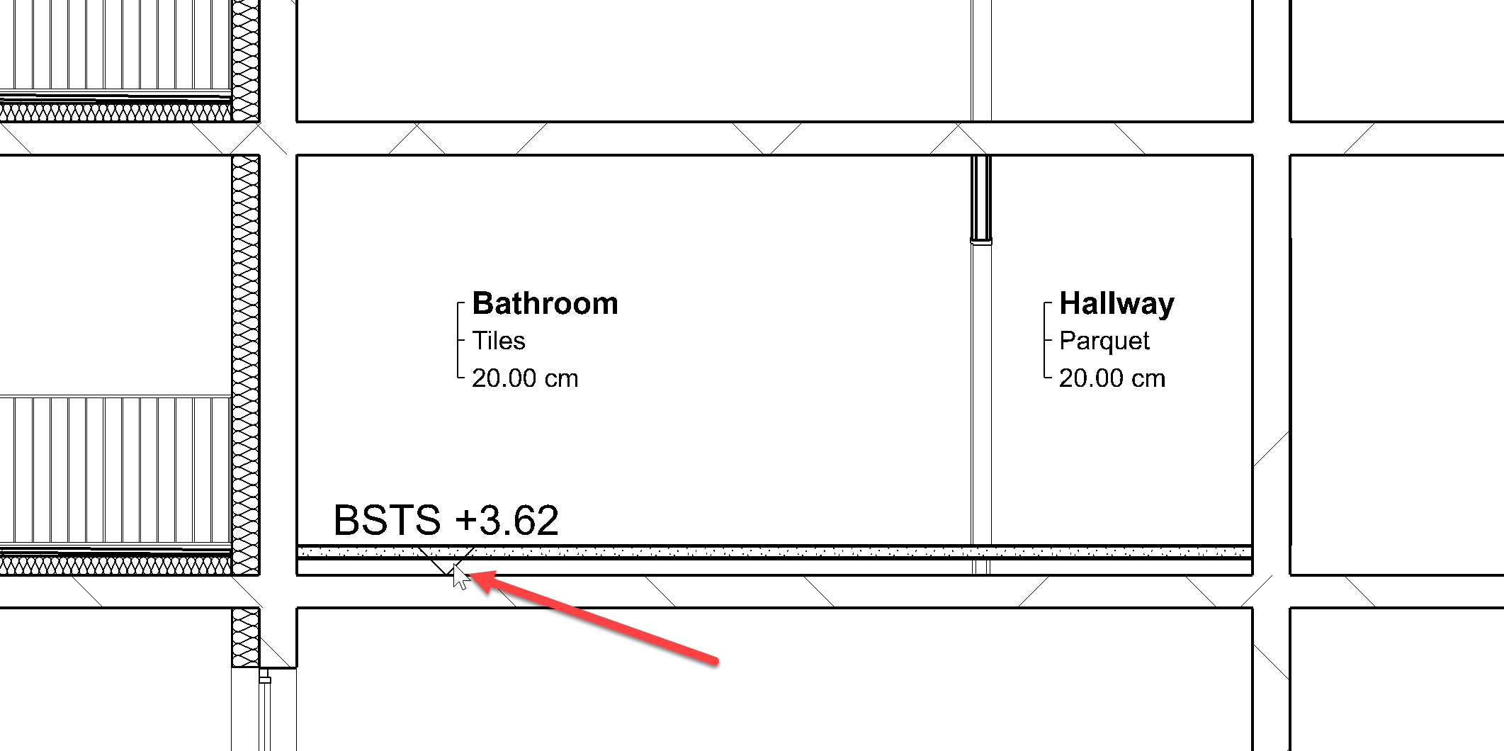
To label these, select the object Height marker from the tools manager Lay-out. From the property bar, select the data record Arial 2.0 empty with the leading text BSTS for bare slab top surface:
Now, you can click on the upper edge of the bare slab and the value will automatically be generated.
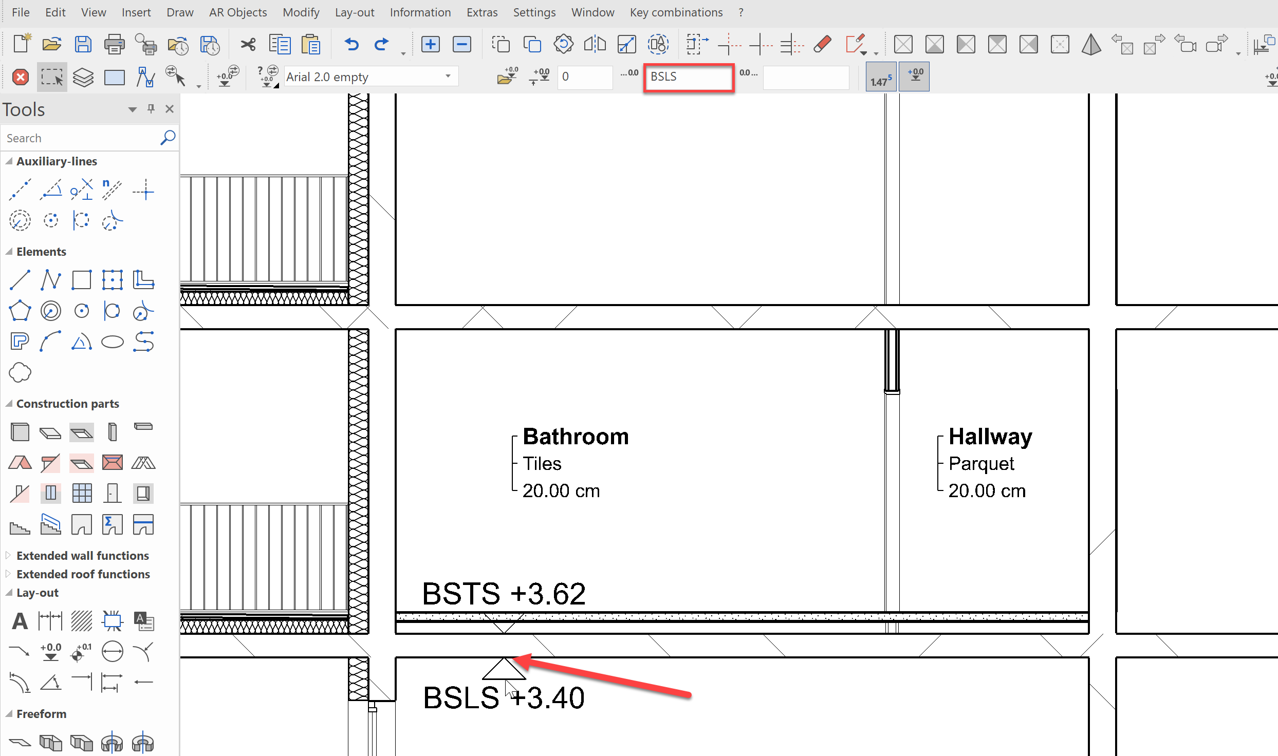
Using the same method, we can label the lower surface just with the leading text BSLS.
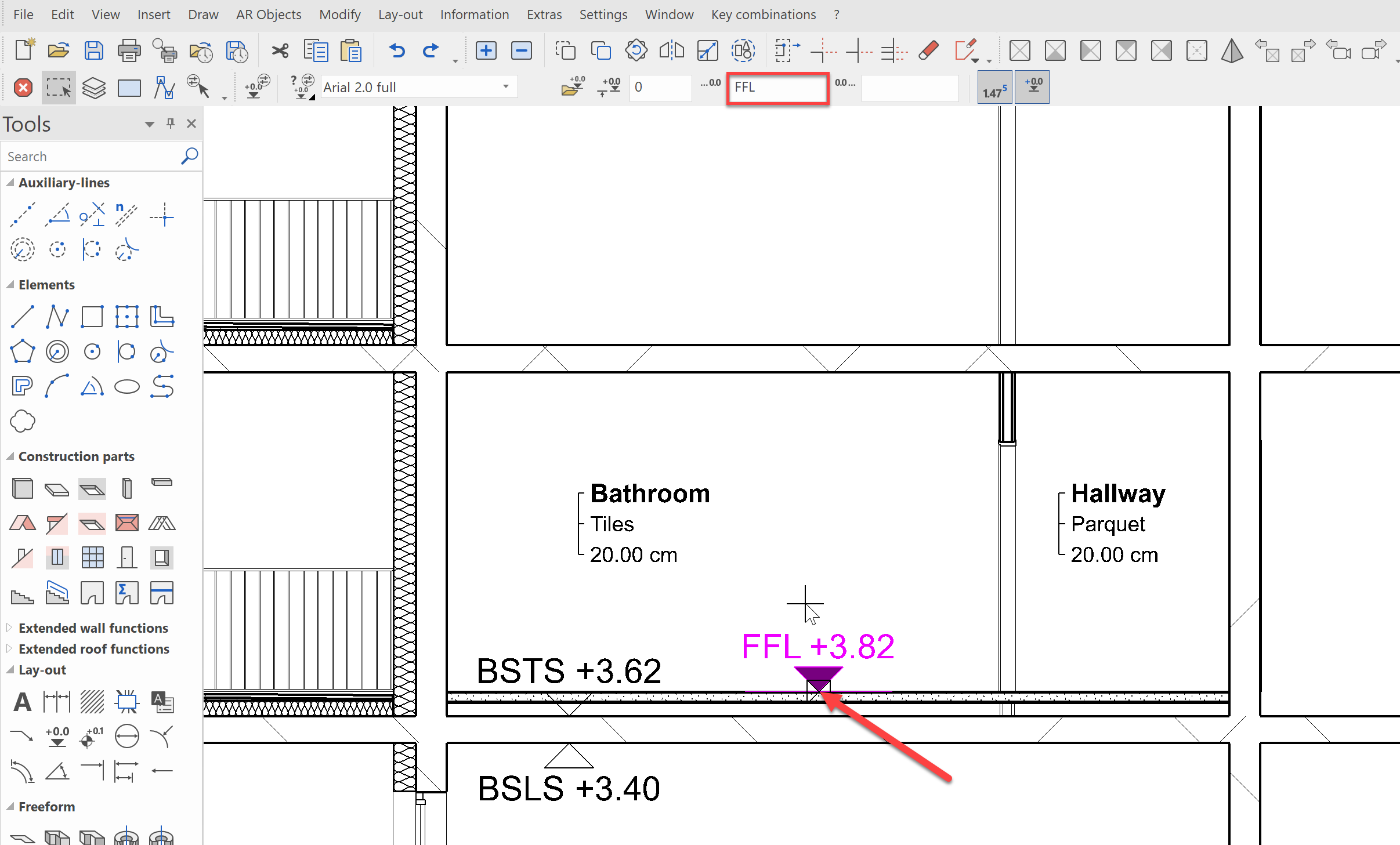
Finally, we want to label the upper edge of the finished floor. This time, select the data record Arial 2.0 full with the leading text FFL
Dimensioning
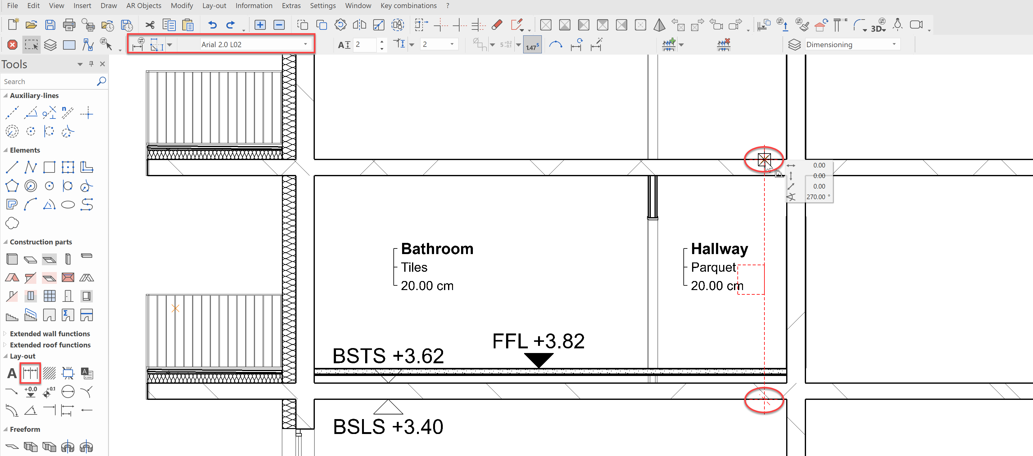
Let's place a parametric chain dimension in the section now. For this, select the object Chain dimension and select the data record Arial 2.0 L02 from the property bar.
The chain dimension is first defined by two points, then the position is defined and finally any number of further points can be linked to the dimension chain. We will start by selecting a point on the corner of the underside of the bare slab, then one just above that from the topside of the bare slab. Then you set the position, e.g. slightly inward from the wall.
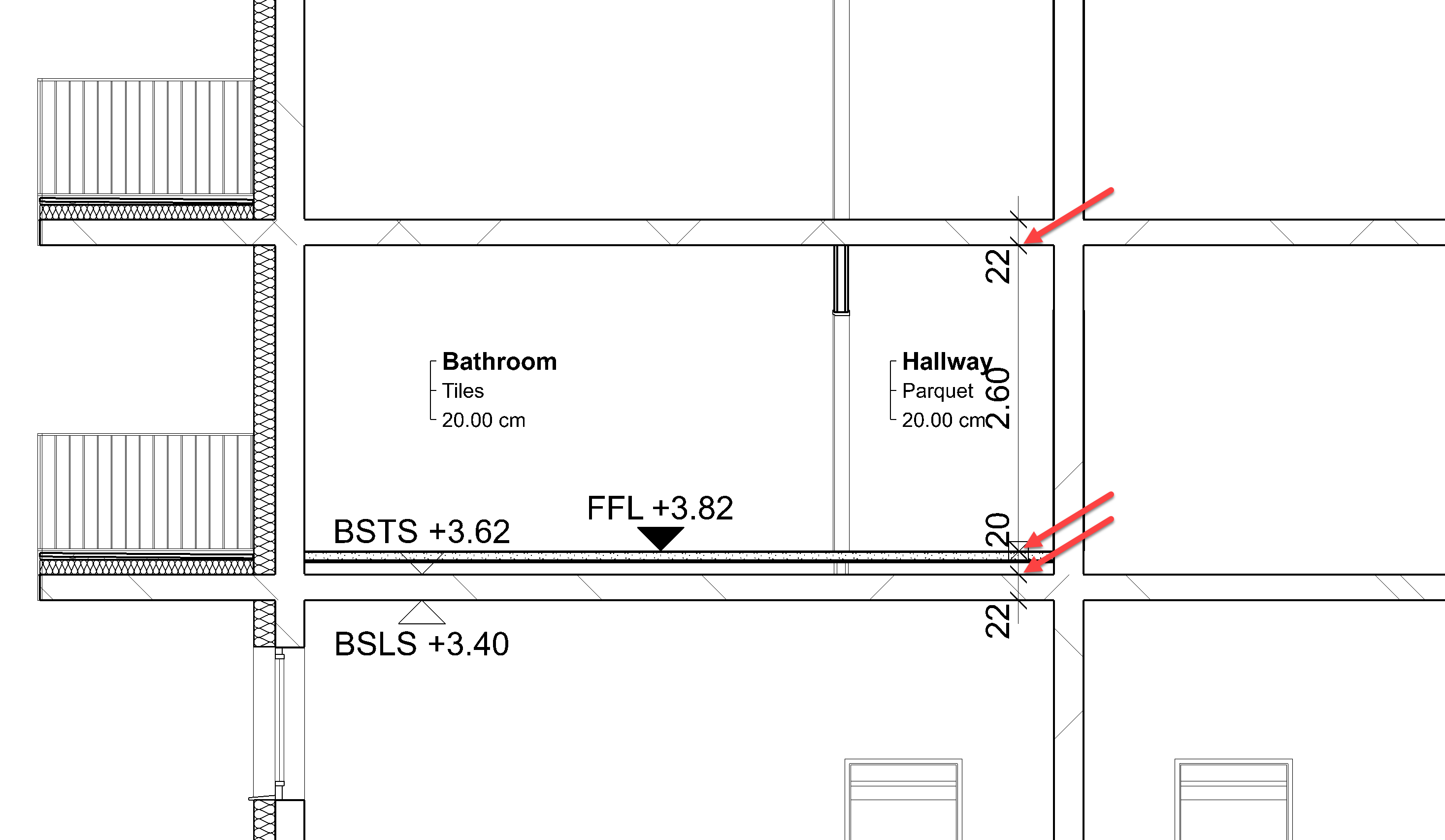
Now you can set further points as you wish, e.g. all bare slabs top- and undersides as well as the finished floor levels. The result could look like this:
PDF export
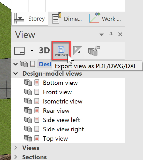
The plans, we worked so hard on, will need to be submitted to our customers, regulatory offices as well as our project partners. ELITECAD offers many interfaces to help with this. The most common formats for 2D data are still PDF and DXF/DWG. To create PDFs from our model, we open the PDF batch export from the Views manager.
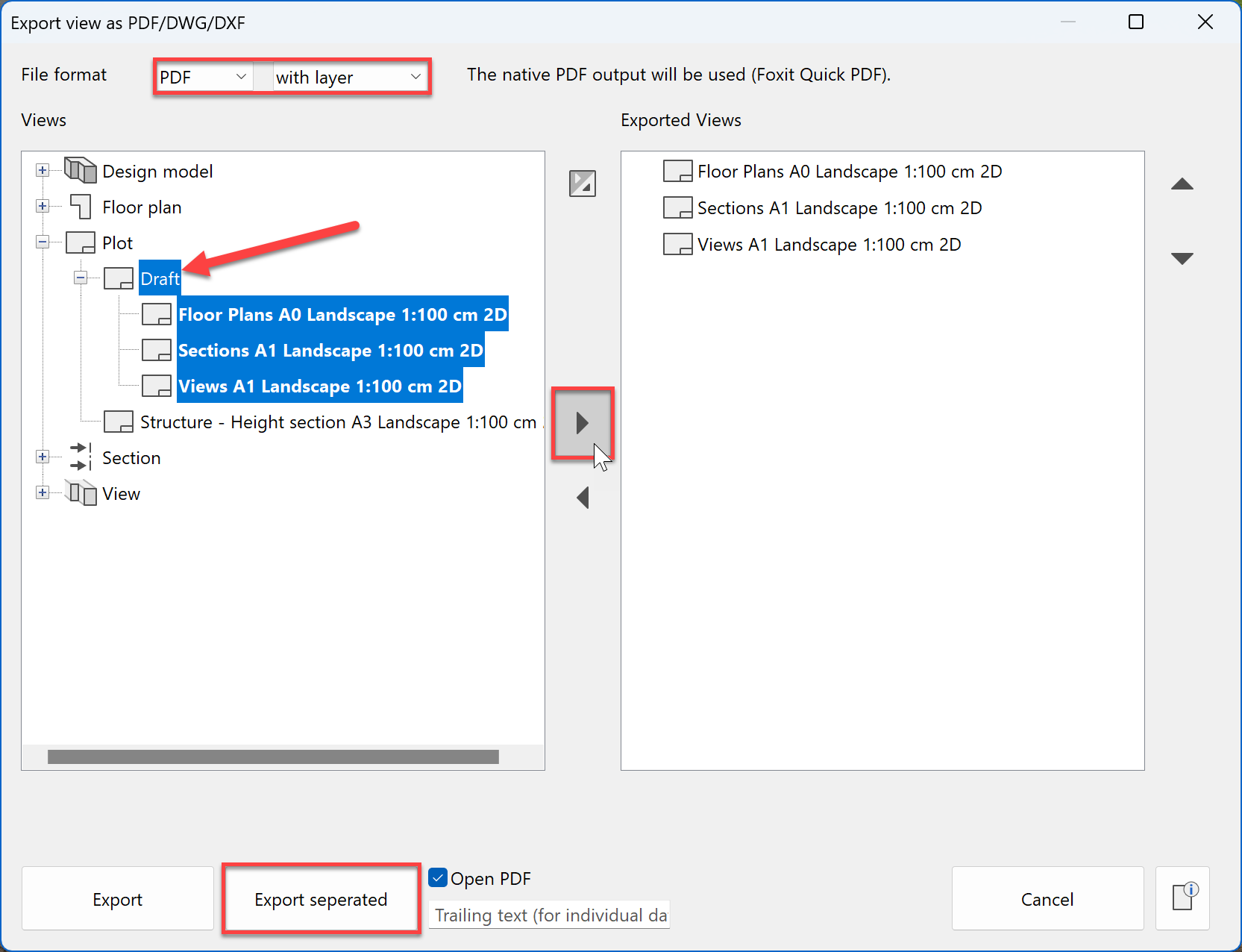
With the PDF export manager, you can create all plots at once using the batch export. The PDFs will be created with the existing layer structure. That way these can be set visible or invisible by your project partners using a PDF reader.
Now select the 3 plots Views, Floor plans and the sections from the Draft folder and slide them with the cursor to the right side. You can create the PDFs as a complete file or as individual files.
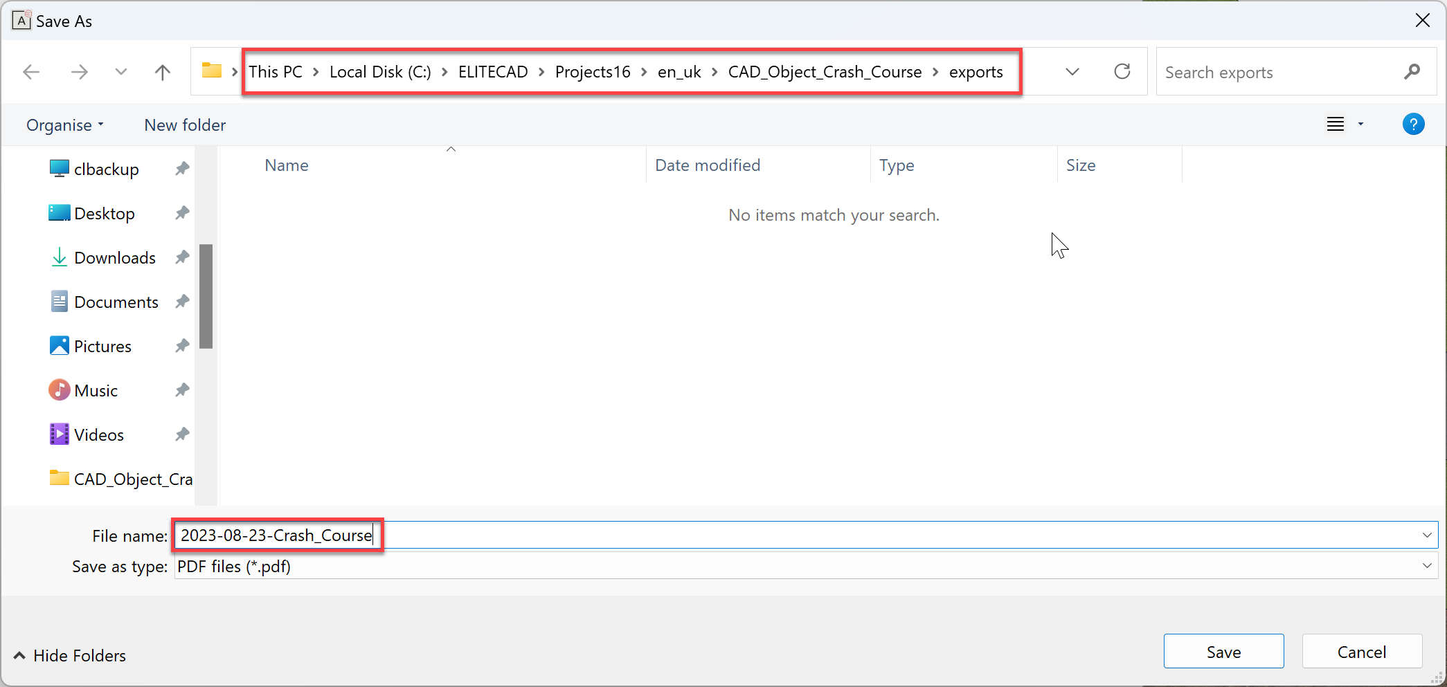
Now you must enter a name and select the save location - e.g. Date-Project_name
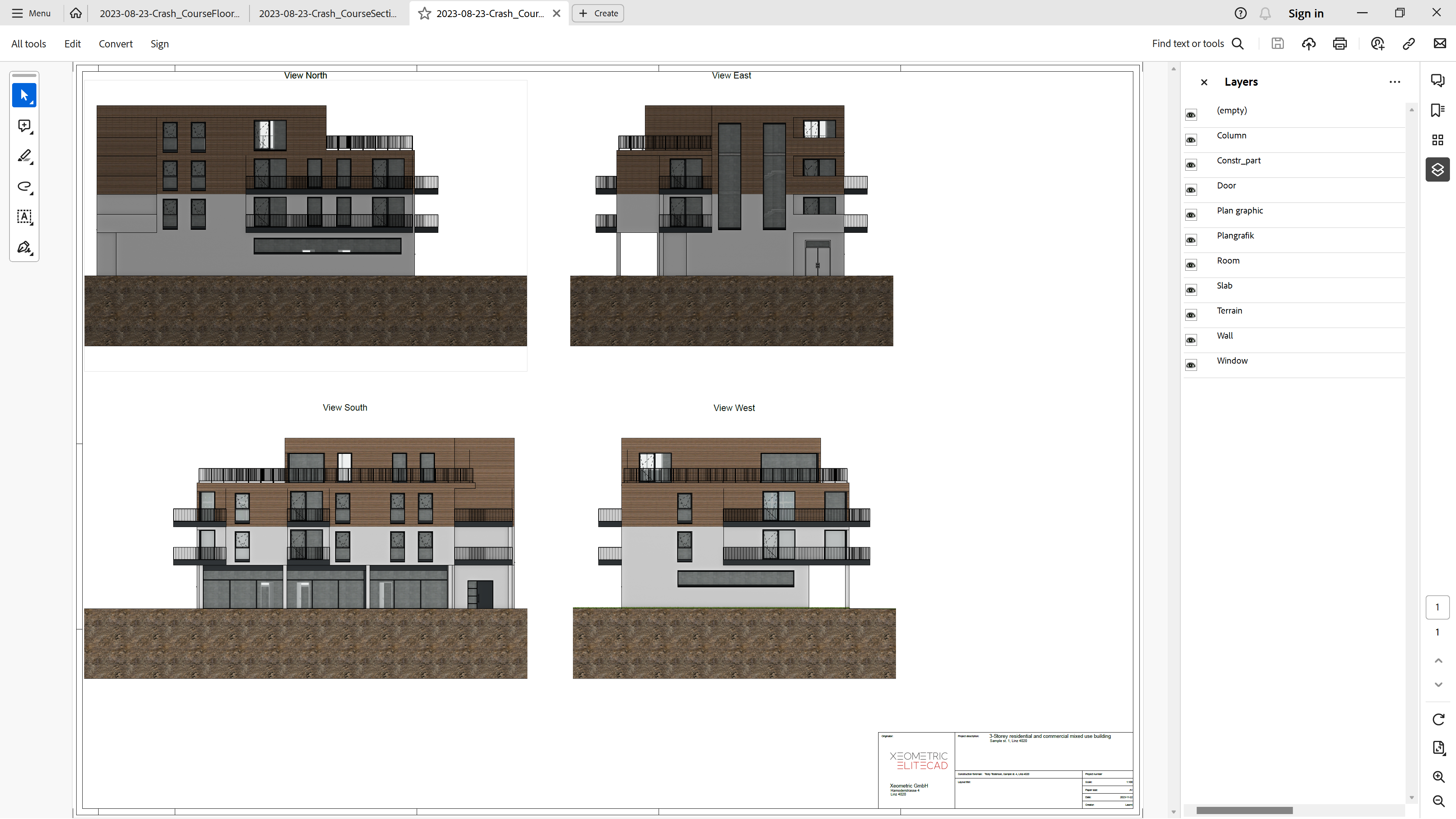
You can now open the exported PDFs in a PDF viewer of your choice and optionally switch the layers invisible:
So, you see, if you work in ELITECAD with project templates, after the 3D modelling of the building, you will very quickly derive finished 2D plans in your own corporate design. In the next chapter, we will look at what information, we can still derive from the 3D building model.