Project start
In ELITECAD, all 3D as well as derived 2D data of a model are managed in a drawing file. Additionally, multiple drawings for a project can be collected. With the use of projects, it can be assured, that the structure settings and storey information remain consistent even over many drawings.
Projects are managed directly in ELITECAD and can also be isolated using network paths. This is especially useful when several project parts are being worked on as individual projects in Team-Mode.
Project templates
A big advantage of ELITECAD is that by using the project templates, a large portion of the manual prep-work is already done automatically by the program so that you can get from draft to the final plot with your own corporate design with very few steps. With project templates, not only will the structure and storey information be pre-loaded, but also all views, sections and plots that have been done thus far. You must only enter the building contour and then, with just a few clicks, you already have a 3D dimensioned model and the derived 2D plans.
Open project template
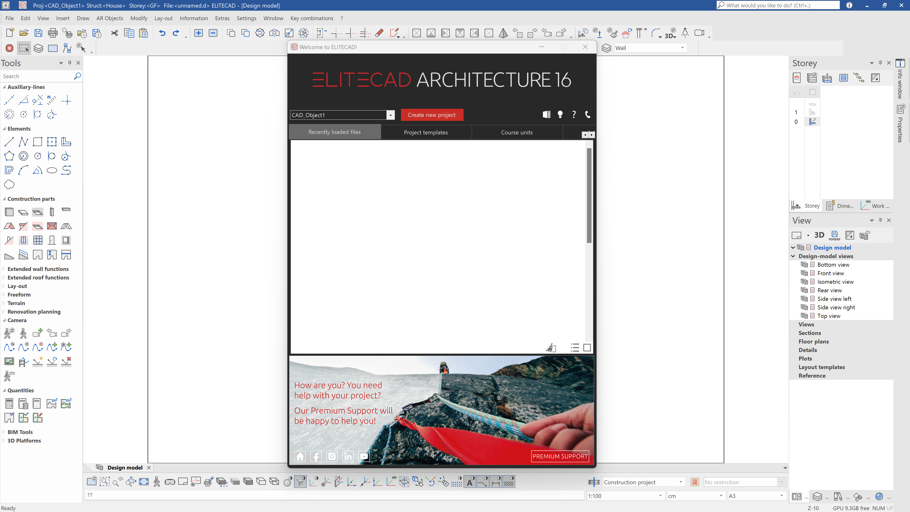
So that we can get started with our project, we first open a corresponding project template. The project templates can be loaded, for example, from the Welcome Screen. Open the Welcome Screen from the title bar.
![]()
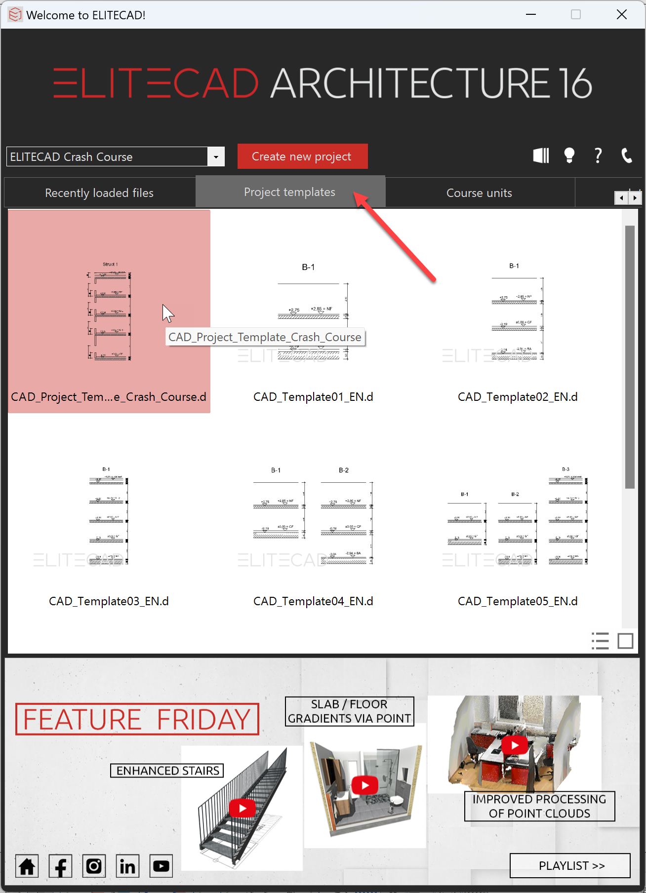
Switch to the project templates tab and select the template CAD_Project_Template_Crash_Course_EN.d with a double click.
Note
Should the project template not be available, they may not be installed. You can download the template after the fact from our website and copy it into your project template folder. The next time you start ELITECAD, it should be available.
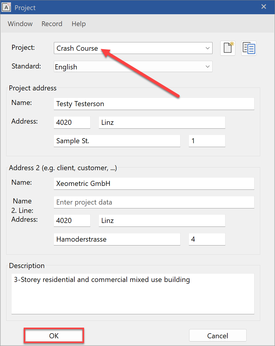
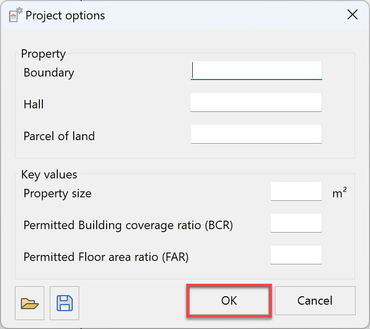
Now you can complete the first task for your project. This information will later be automatically included into your plots. You can, of course, adjust these in the course of your project.
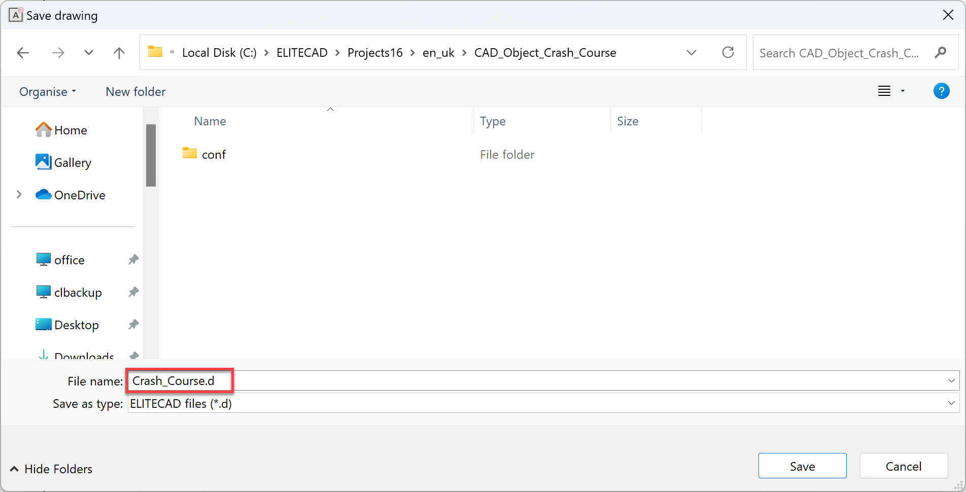
Next, we need to define a drawing file for our project. This will include the entire building model as well as the 2D plans.
If we already have important key values and boundaries for our property, we can enter them here. These will be automatically compared to the calculated values of the building model, and ELITECAD will inform us of any specific values that exceed them. In our case, the fields will remain empty and we confirm the dialog.
The project and the drawing will not be successfully created and we can see, that the project template already contains a pre-defined axis grid. This will make our drawing of the building contour easier. In the lower right area, we see in the views manager, that the views, sections and plots are already pre-defined.
![]()
Create structure
In the following step, we will already begin with the modelling of our building envelope. For our project, we first want to draw the entire structure as a 2D polygon and step by step form the facade. For this, we start the 2D drawing function and create a polygon.
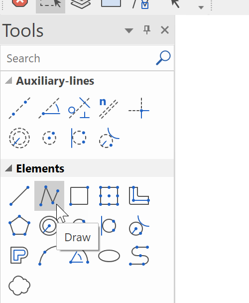
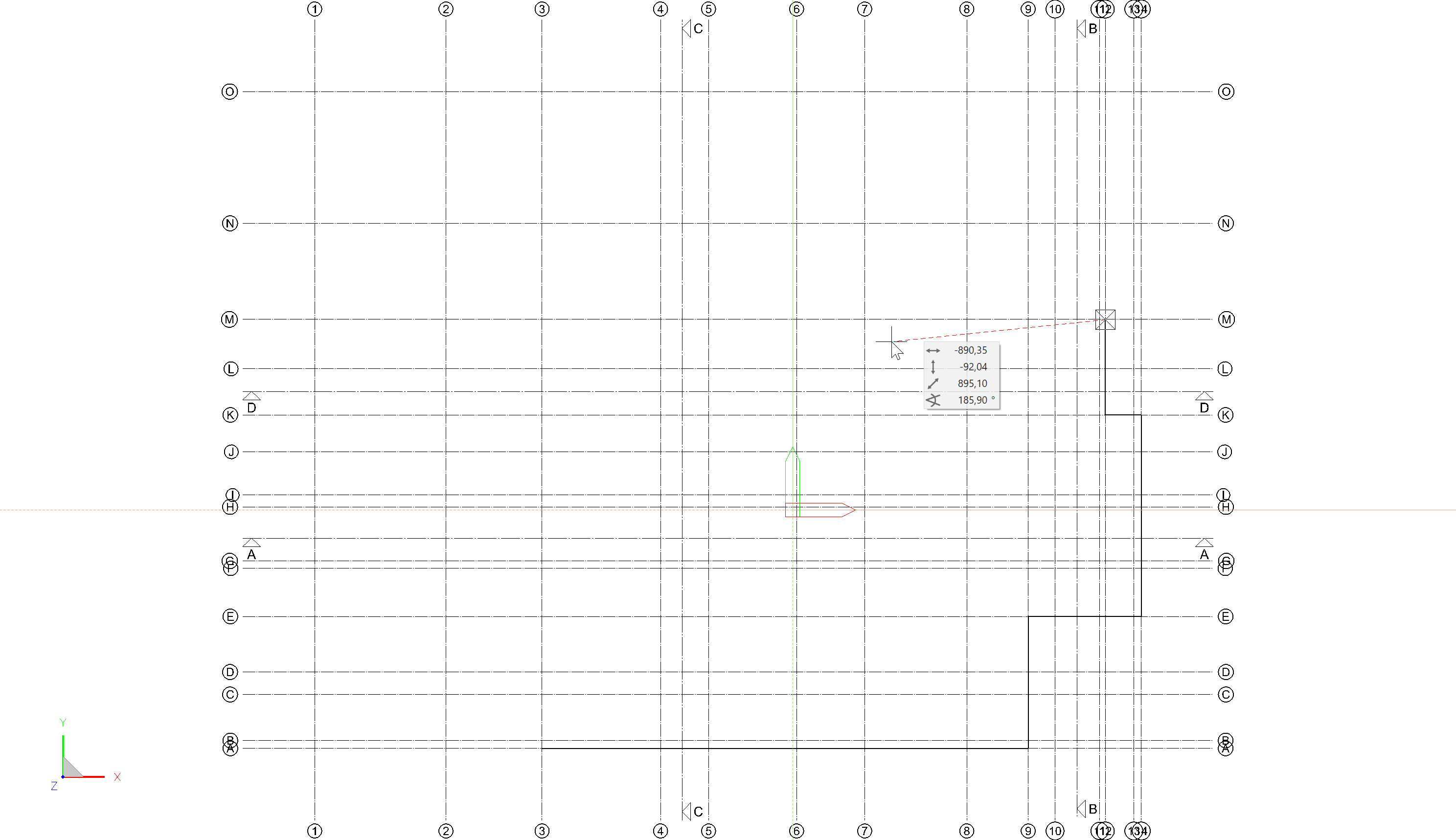
As soon as the drawing function is started, we can start capturing the points on the axis grid. We now want to draw a polygon over the following points:
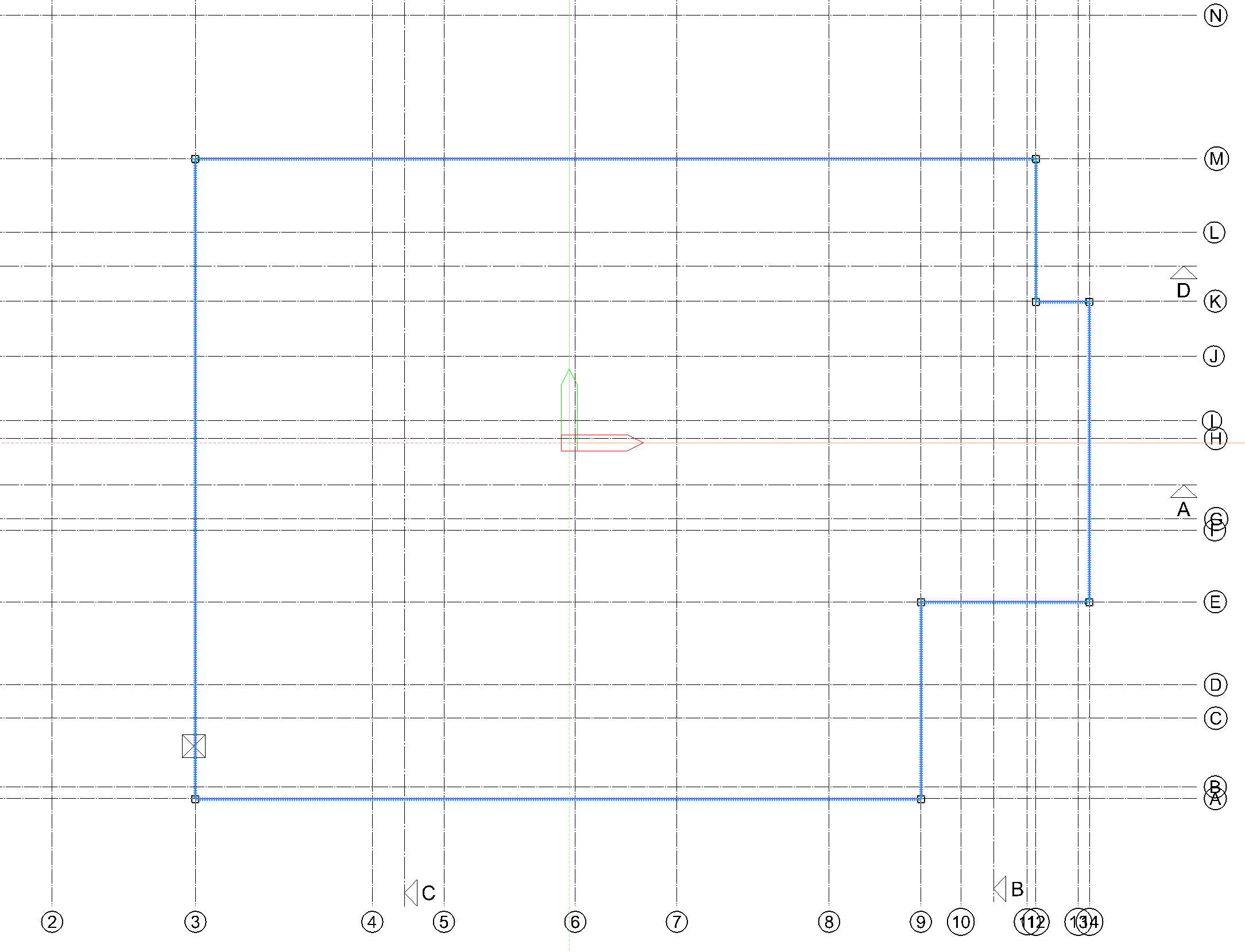
A3-A9, A9-E9, E9-E14, E14-K14, K14-K12, K12-M12, M12-M3, M3-A3
The polygon is expanded with every click of the left mouse button. To close the polygon, the last point must be double clicked. Alternatively, the polygon can also be ended automatically with the Enter key.
The polygon is now drawn in a 2D work plane but it also exists as a 3D geometry and serves as the basis for our structure in the next step.
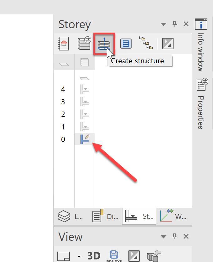
If the contour was successfully created, we can now create the structure. To do this, we will use the function ![]() Create structure Prior to starting this function, we must ensure that the structure is active. If the structure is greyed-out, it is sufficient to just double click on the structure or a single click on the ground floor, in order to activate it.
Create structure Prior to starting this function, we must ensure that the structure is active. If the structure is greyed-out, it is sufficient to just double click on the structure or a single click on the ground floor, in order to activate it.
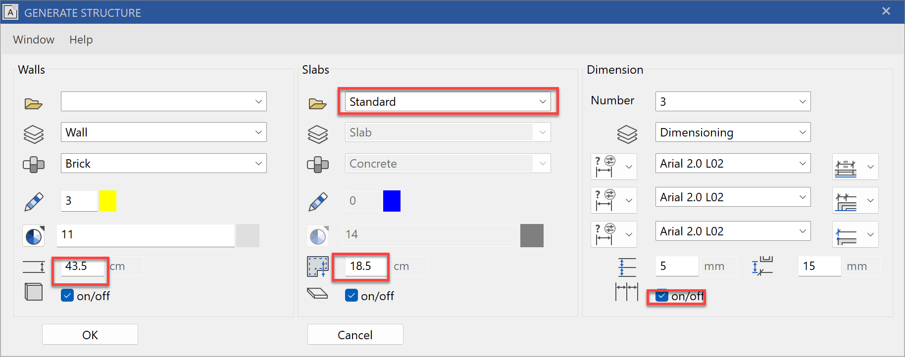
Finally, we must determine which materials and in what thicknesses should be built. We could choose from our pre-defined wall and slab constructions or define our own. We will define our own brick wall with a thickness of 43.5 cm, select the pre-defined Standard slab and set it to evenly offset inwards by 18.5 cm. We will active the automatic dimensioning as shown below. Should the input fields be greyed out, then the respective check box below needs to first be activated.
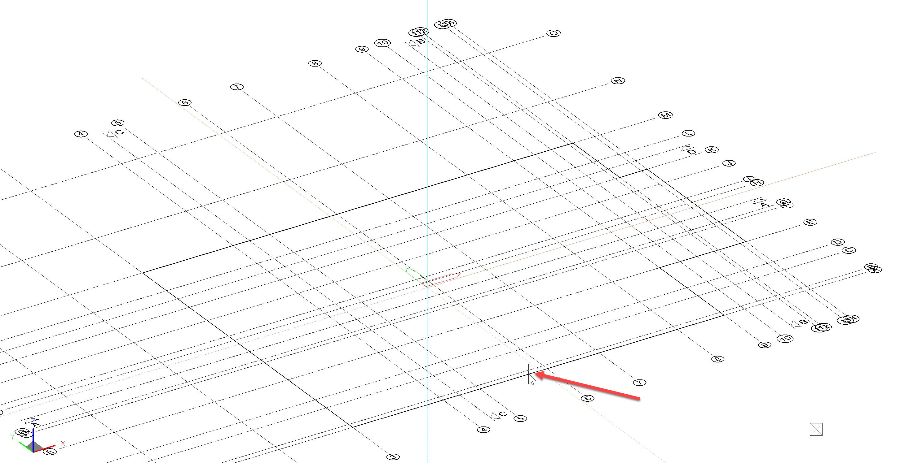
Once the dialog is confirmed with OK, the query "Create which structures" appears in the input bar. Select the previously created 2D contour. For a better view, you can also rotate (hold mouse wheel and move) the contour beforehand.
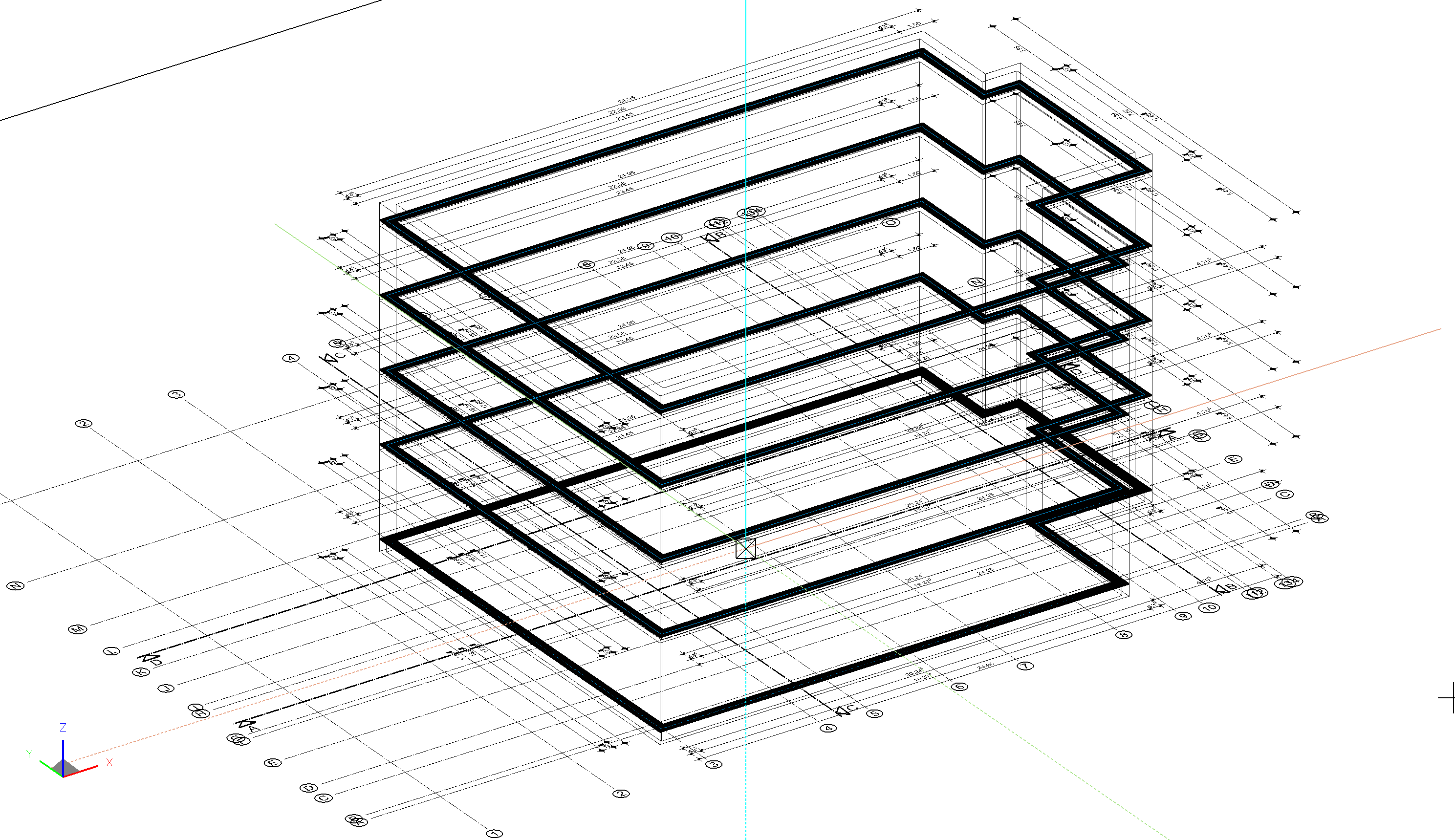
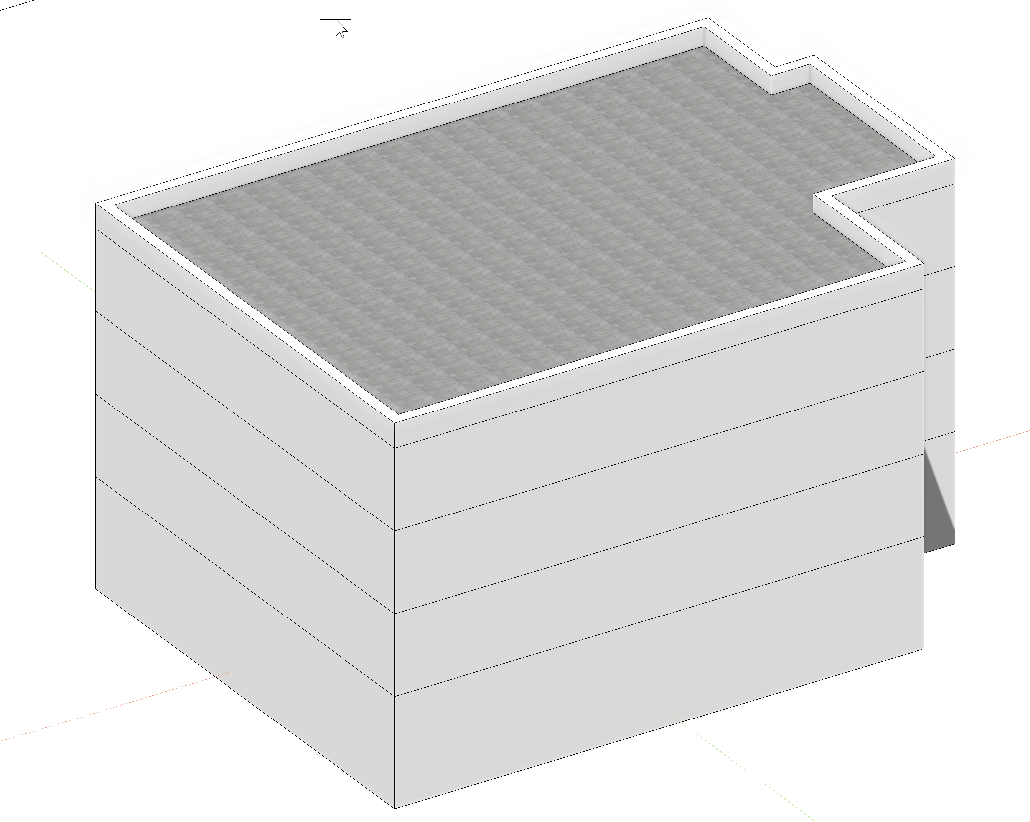
Once you have clicked the contour, the structure with all automated chain dimensioning is created according to the storey settings. The result should look like this:
Now using Ctrl+D, switch to the solid mode and take some time to become familiar with the controls. Test out the different short cuts for changing the depiction form the previous chapter and practice the visibility controls from the storeys manager.
Derive the first 2D plans
Even though we are still at a very early stage of our project, we can generate the first plots at the touch of a button thanks to the project templates. If it is not already visible, open the Views Manager ![]() at the bottom right. Choose a plot, e.g. "Floor Plans" and it will be displayed in the graphics window.
at the bottom right. Choose a plot, e.g. "Floor Plans" and it will be displayed in the graphics window.
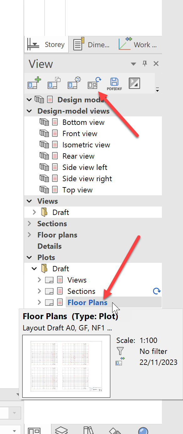
The plot can be updated automatically from the menu bar or by right-clicking.
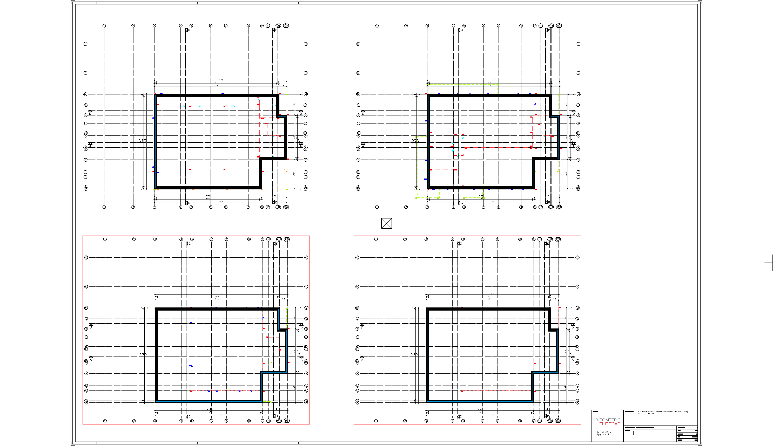
Also check the plots "Views" and "Section". In just a few minutes, we managed to create our first BIM-dimensioned model in LOD (Level of Detail) 100, including extrapolated 2D plans and plots.
Structure Settings
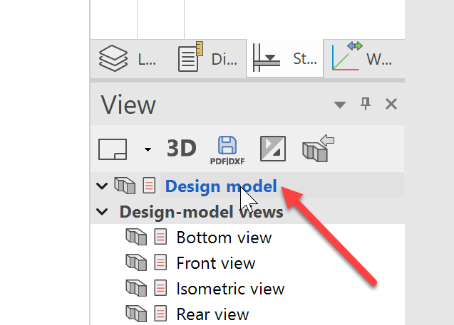
To leave the 2D views or plots and get back into drawing mode, switch back to the 3D view by clicking on "Model".
Now let's take a look at why our building model could be generated automatically with so few clicks. Open the Structure settings ![]() from the storeys manager.
from the storeys manager.
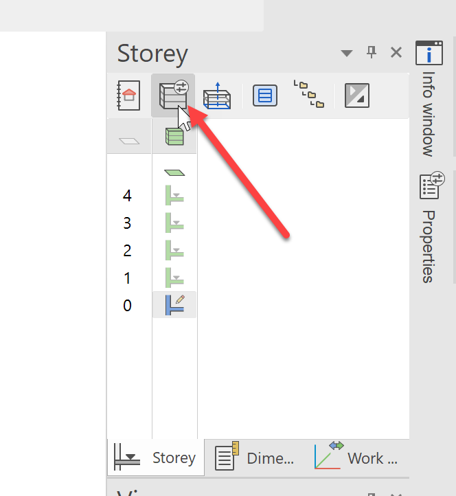
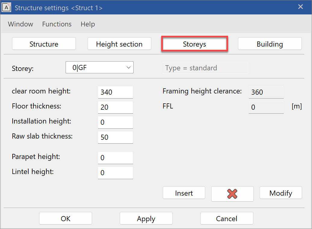
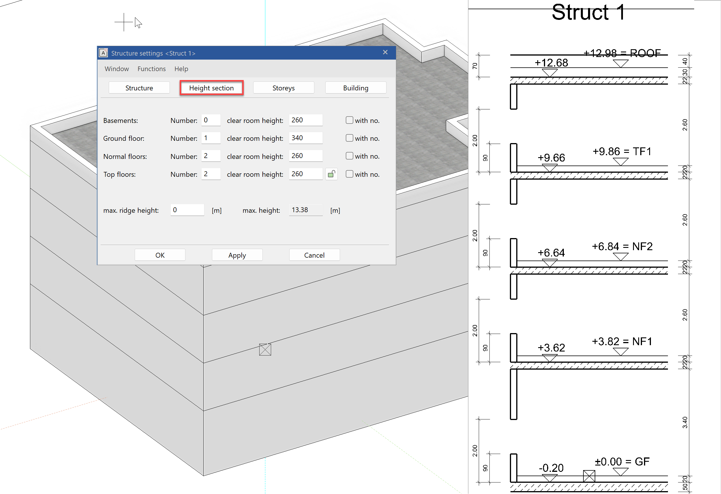
This is where all the key values for the building that were already predefined in the project template are. The settings define how many structures are needed, the storey count per structure as well as room heights, floor thicknesses and parapet heights. Of course, these values can be set by you or adjusted over the course of the project. Under the "Storey" tab, you can check, for example, the settings per storey.
An automatic height section is also generated based on the settings.
The use of the structure settings has many advantages. All construction elements such as walls, slabs or windows refer to these values and automatically align their geometry. This way changes in storey heights in the course of the project are no problem - with just on correction of a value in the structure settings and all construction parts adjust automatically.