Modeling structures
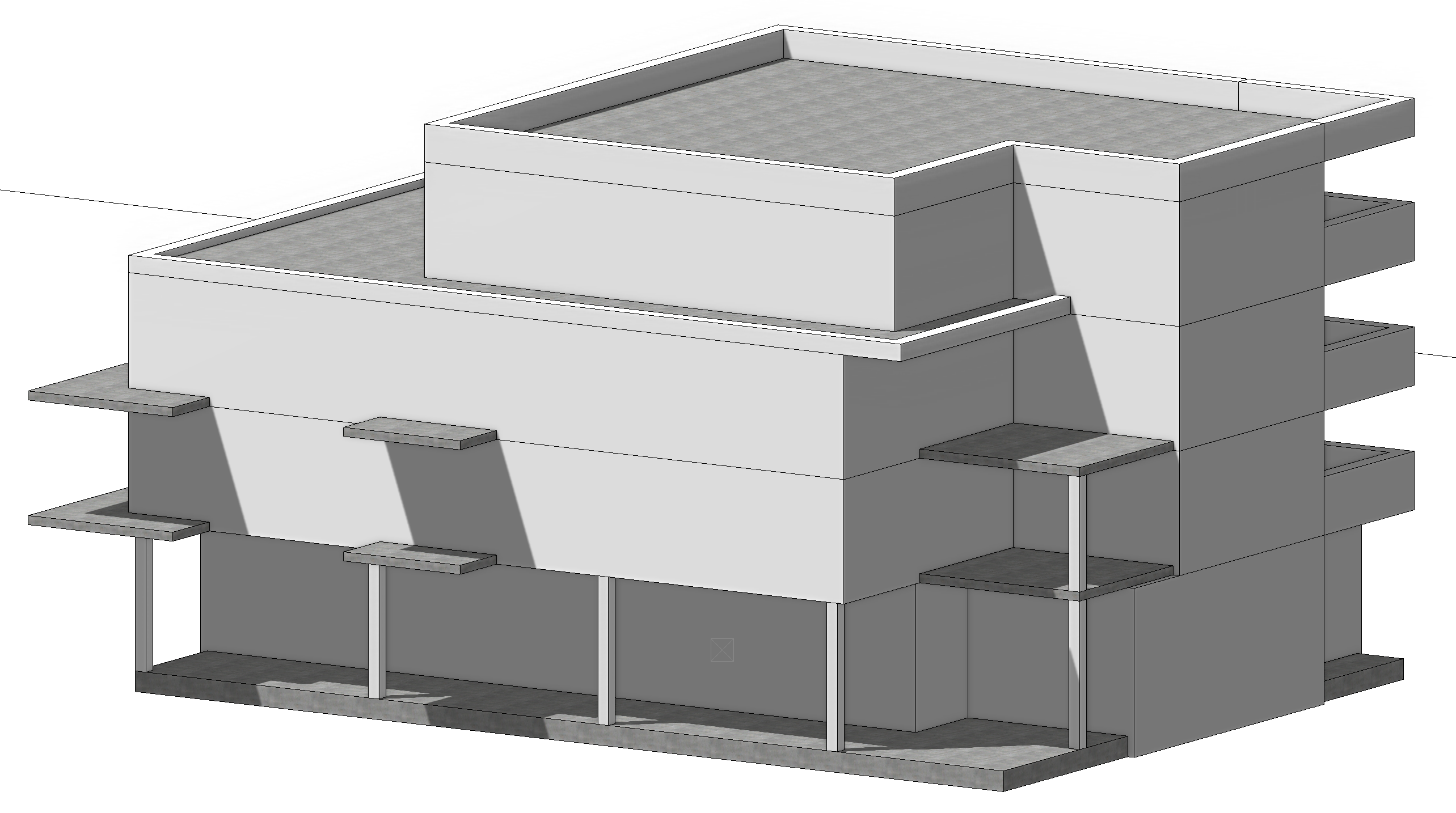
In this chapter, we look at how easy it is to further model the building envelope of the already built structure. The outer walls are to be adjusted, slabs and balconies will be created and columns and parapet walls will be positioned. The first design should be done with single-layer walls even though we already know that a brick wall with ETICS will be installed later. We can already take this into account when offsetting the slabs.
All of the following process steps can be executed in a variety of ways. ELITECAD users choose for themselves if they prefer to work in 2D or 3D or in solid view or in wire model. There are users who prefer to place predefined construction parts and stretch them to the appropriate dimensions, while others prefer to configure all values first and then position a finished construction part. Our aim in this course is to show different variations and approaches - so that you can decide for yourself how you want to work.
To make modeling the building easier for you, we have already predefined all the important points in the model as auxiliary geometry on a separate layer per storey. So that all you need to do is select the desired construction parts and capture the point to get to a quick result.
Exterior walls and slabs
Let's start with the outer walls and slabs and work our way up storey by storey.
Ground floor
On the ground floor, shop windows for sales rooms will be added later, so we would like to pull the front-side wall of the ground floor back a little.
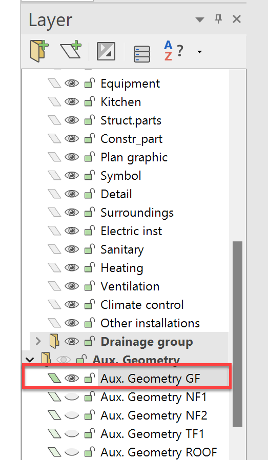
Switch to solid mode, activate the elements and make all floors visible via the storey manager. Then switch the layer Aux. Geometry GF visible via the layer manager by clicking on the eye symbol or with a Right mouse button -> Show.
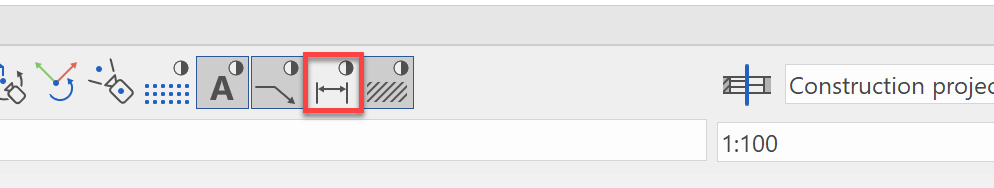
If the chain dimensions bother you while modeling, you can hide them using the switch in the image properties.
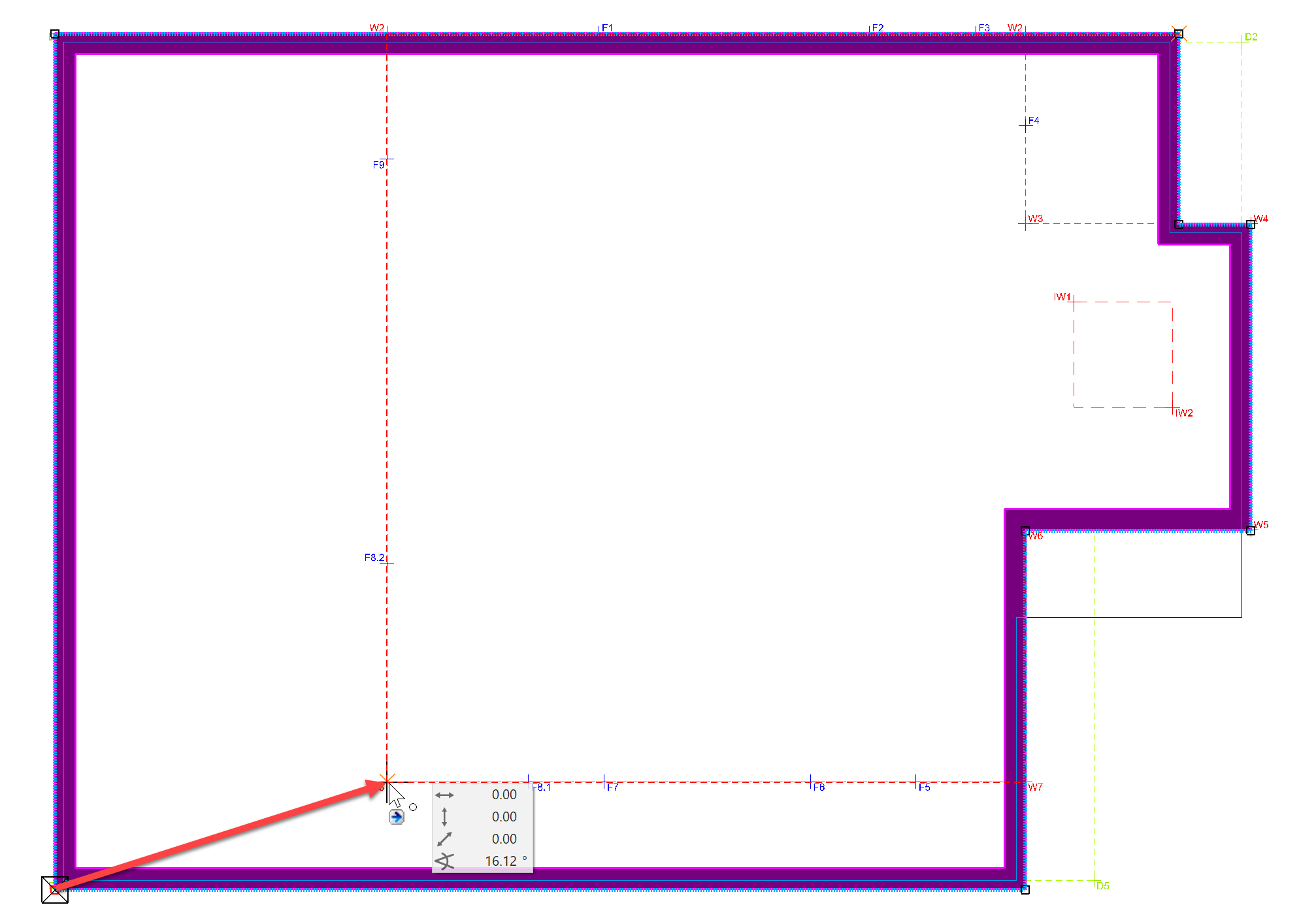
Click on the ground floor wall to activate it. If it is coloured as in the picture below, click on the wall axis in the front area. Now we can move them.
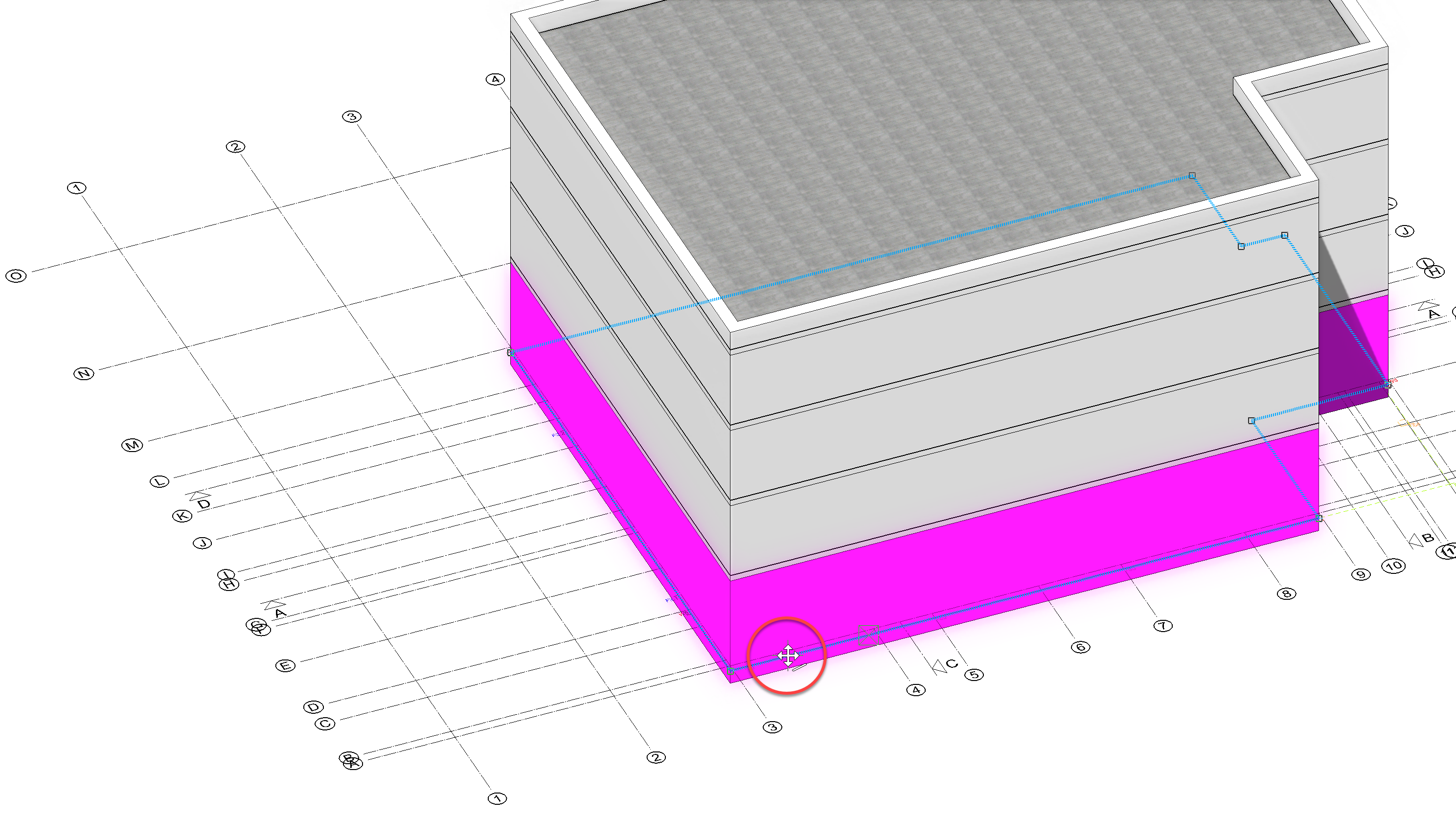
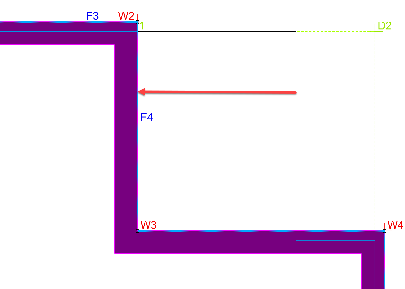
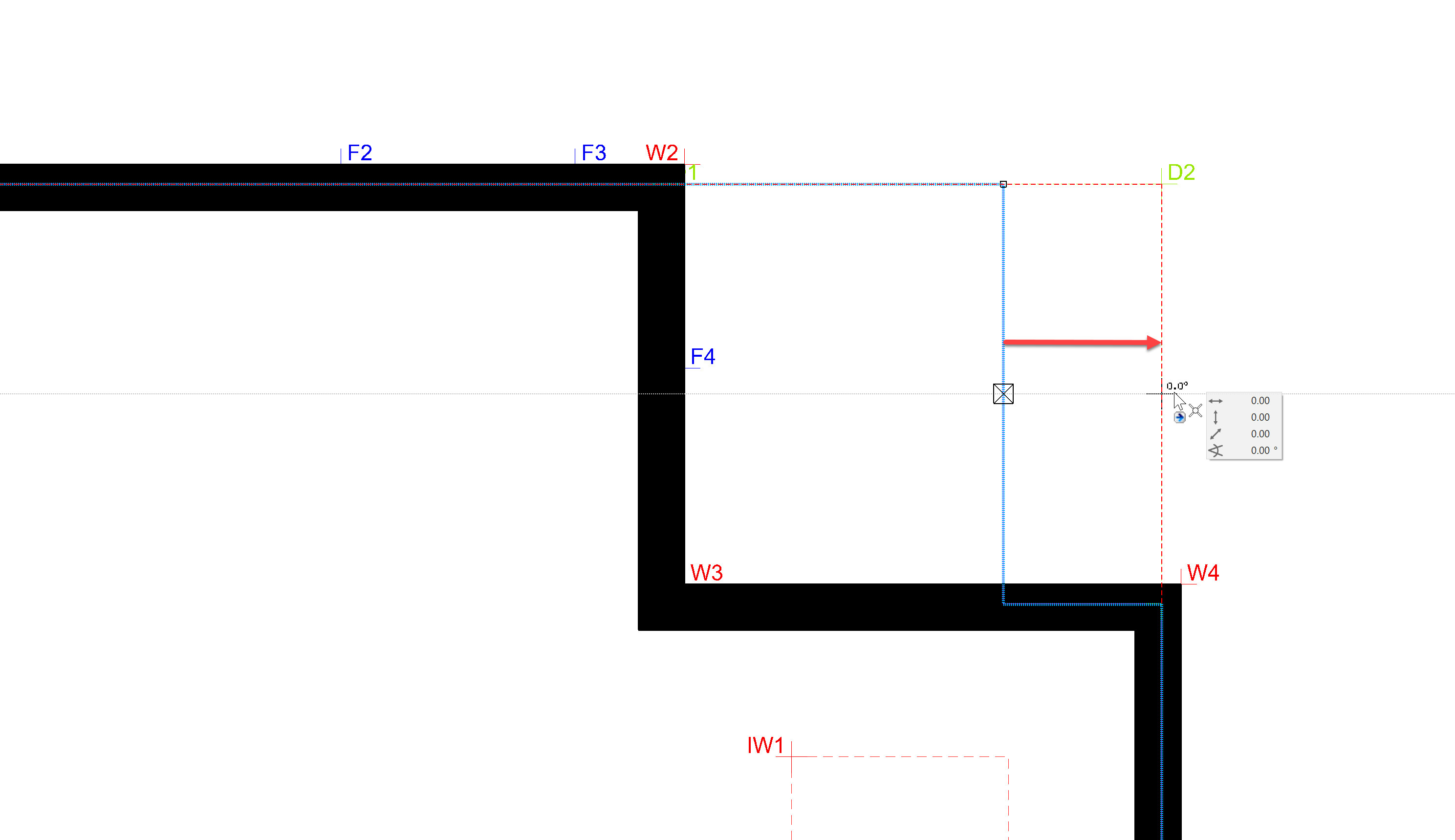
In our case, the wall should be shifted to Axis D on the axis grid. Click on the end of the line as shown in the below picture.

If you selected the correct axis, the result should look like this:
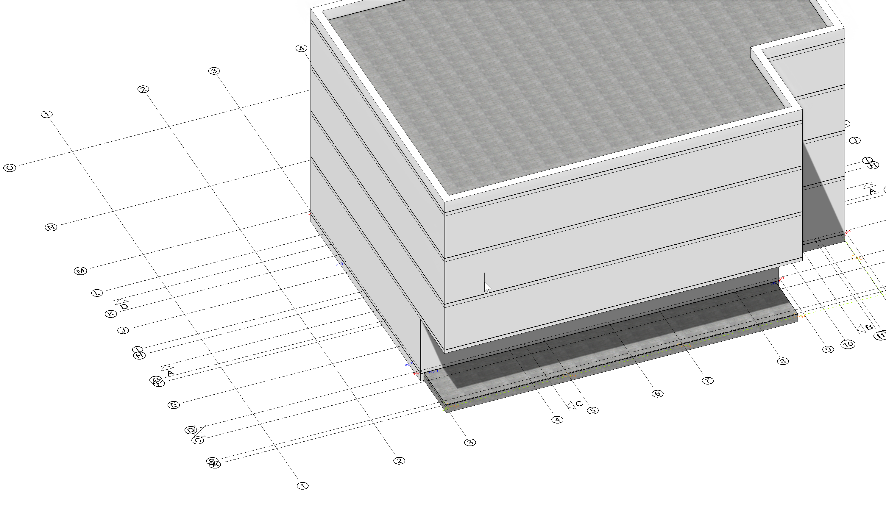
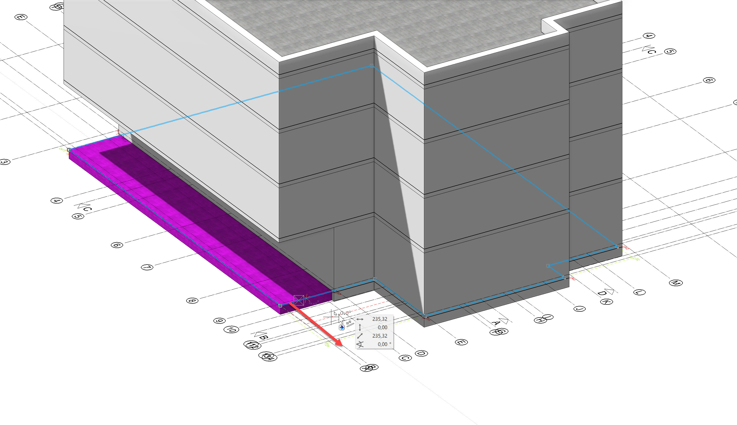
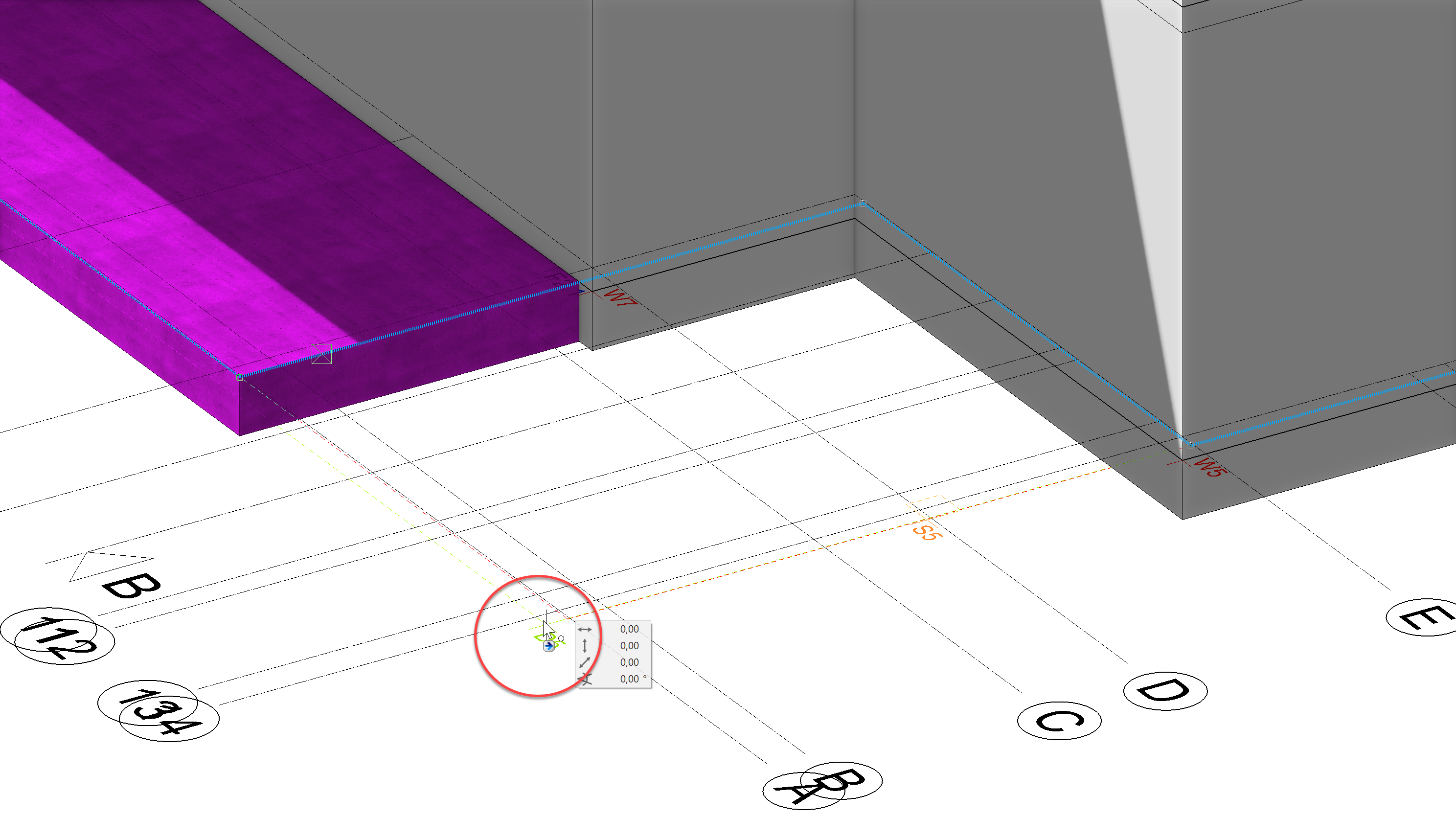
In the next step, the foundation slab should be extended, so that we can place support columns later. First, select the foundation slab then select the contour and drag this to Point D5 of the auxiliary geometry.
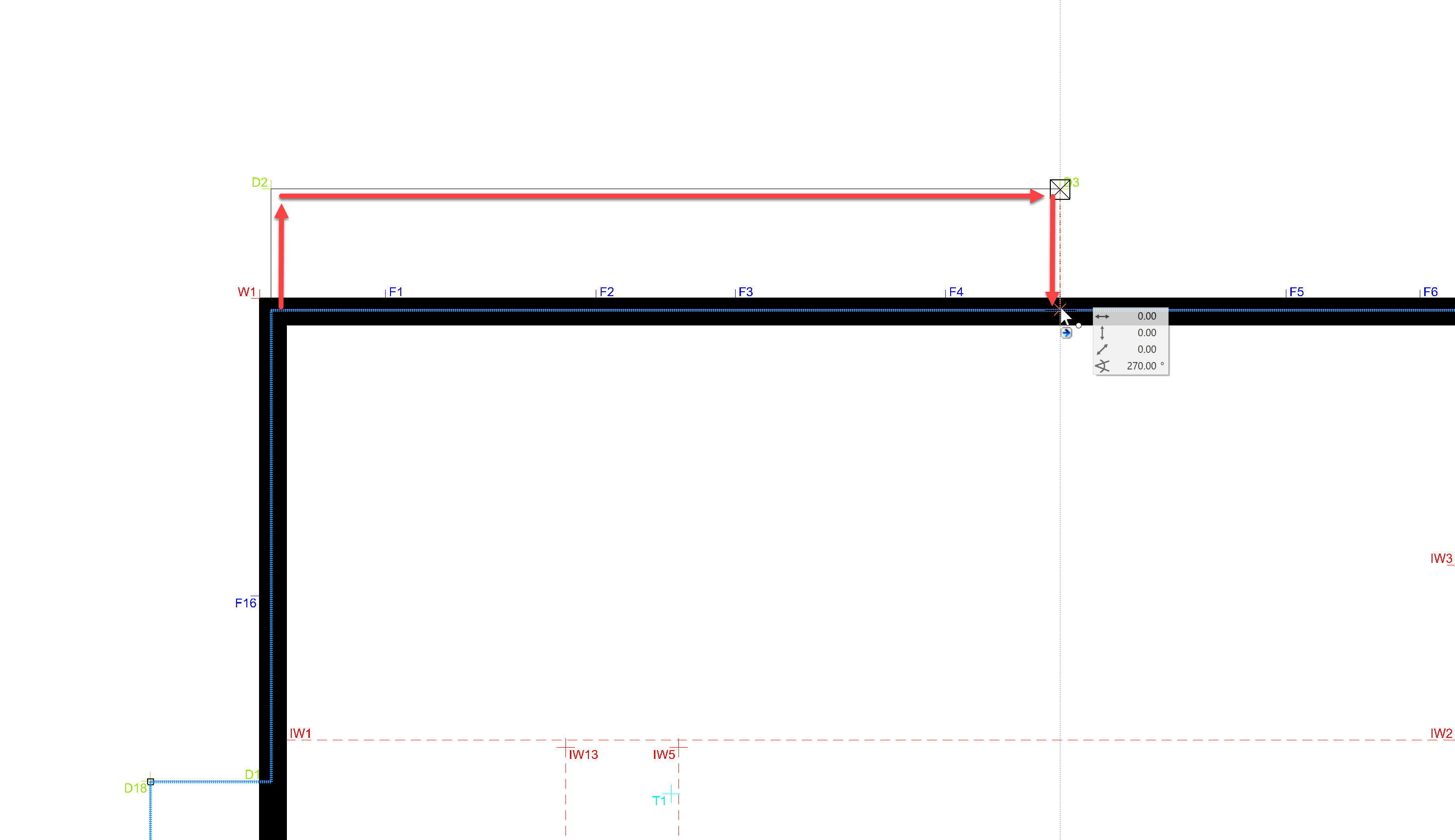
Also, on the backside, the foundation slab needs to be extended to Point D2. You can extend this from any side. Attention - The slab must already be selected or else you will not be able to capture the contour.
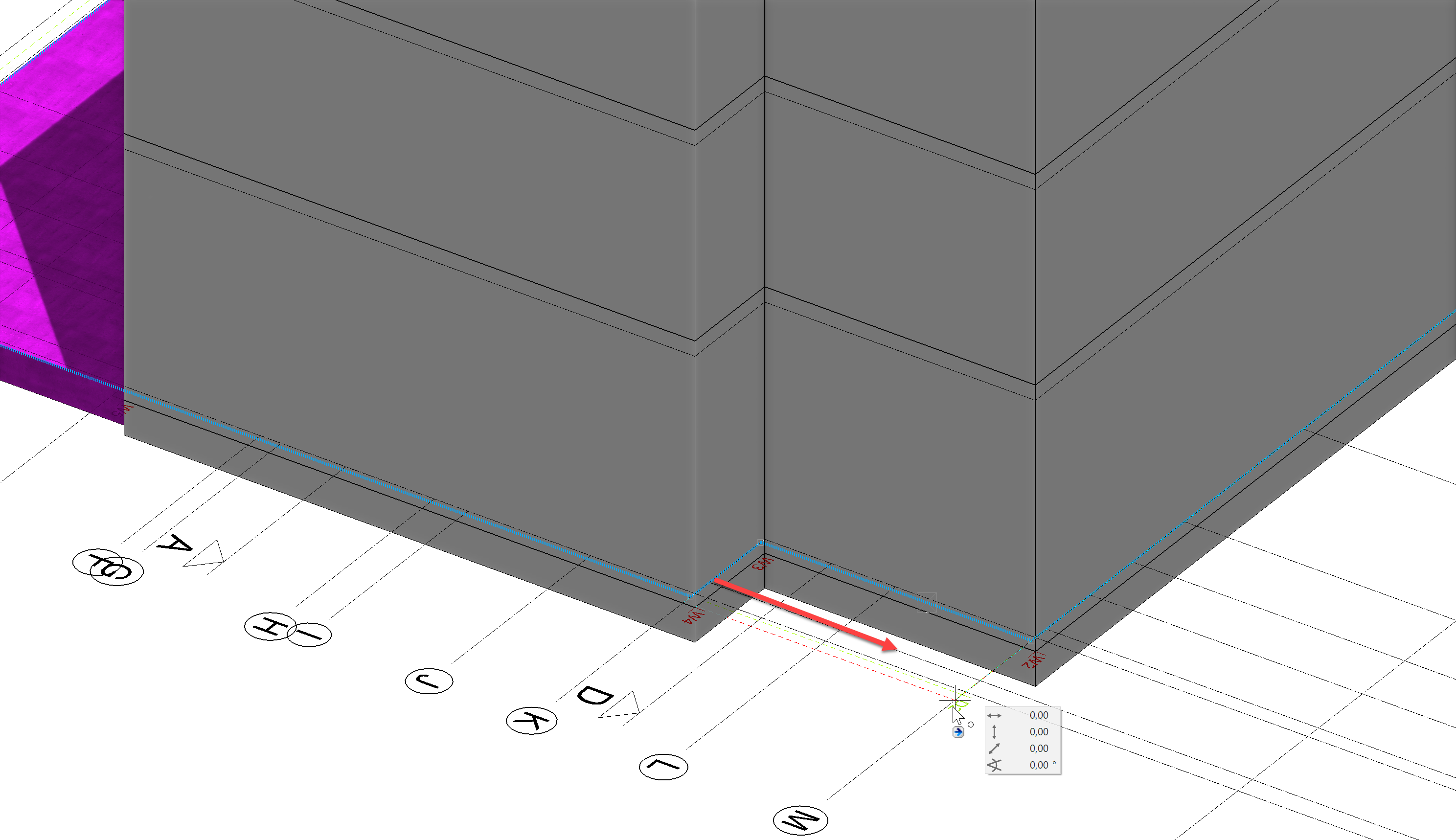
The result should look like this:
First floor
In ELITECAD, you always work on a central building model, regardless of whether you are drawing in the 2D floor plan view or on the 3D model, the other depiction is created automatically. We modeled the ground floor directly in the 3D view. For the first floor, we will now manipulate the slabs and walls in the 2D view.
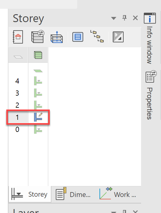
To this end, we will show the first floor using a double click in the storey manager. Using Ctrl+Space, bring the model back to the origin floor plan view and to wire model view with Ctrl+D.
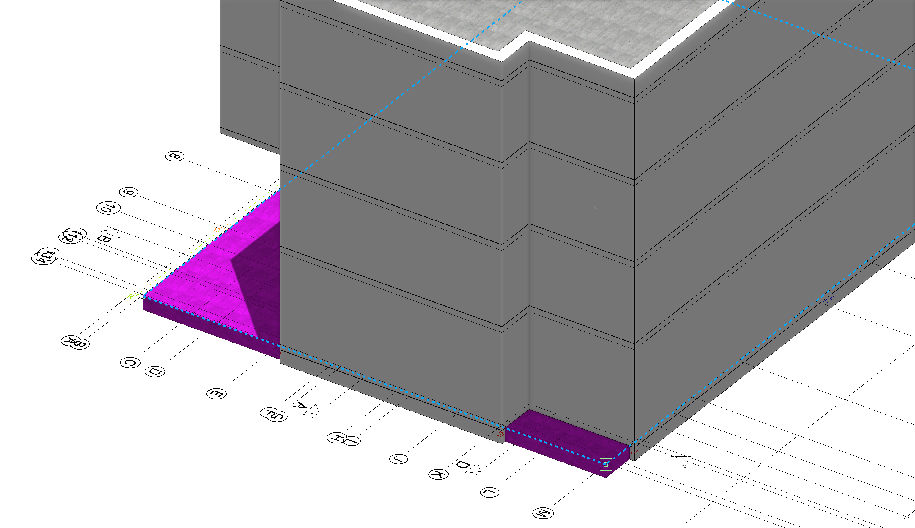
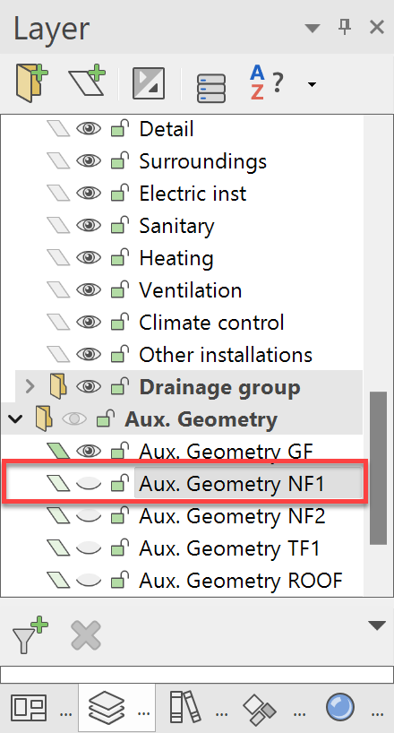
Afterwards, switch the layer Aux. Geometry NF1 visible. This contains the capture points for the next steps.
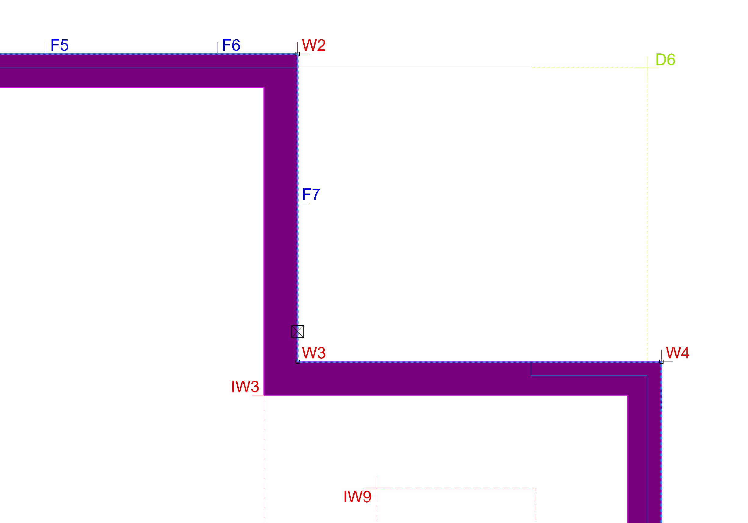
Next, there should be a balcony on the back. First, select the wall then move the contour Point W3.
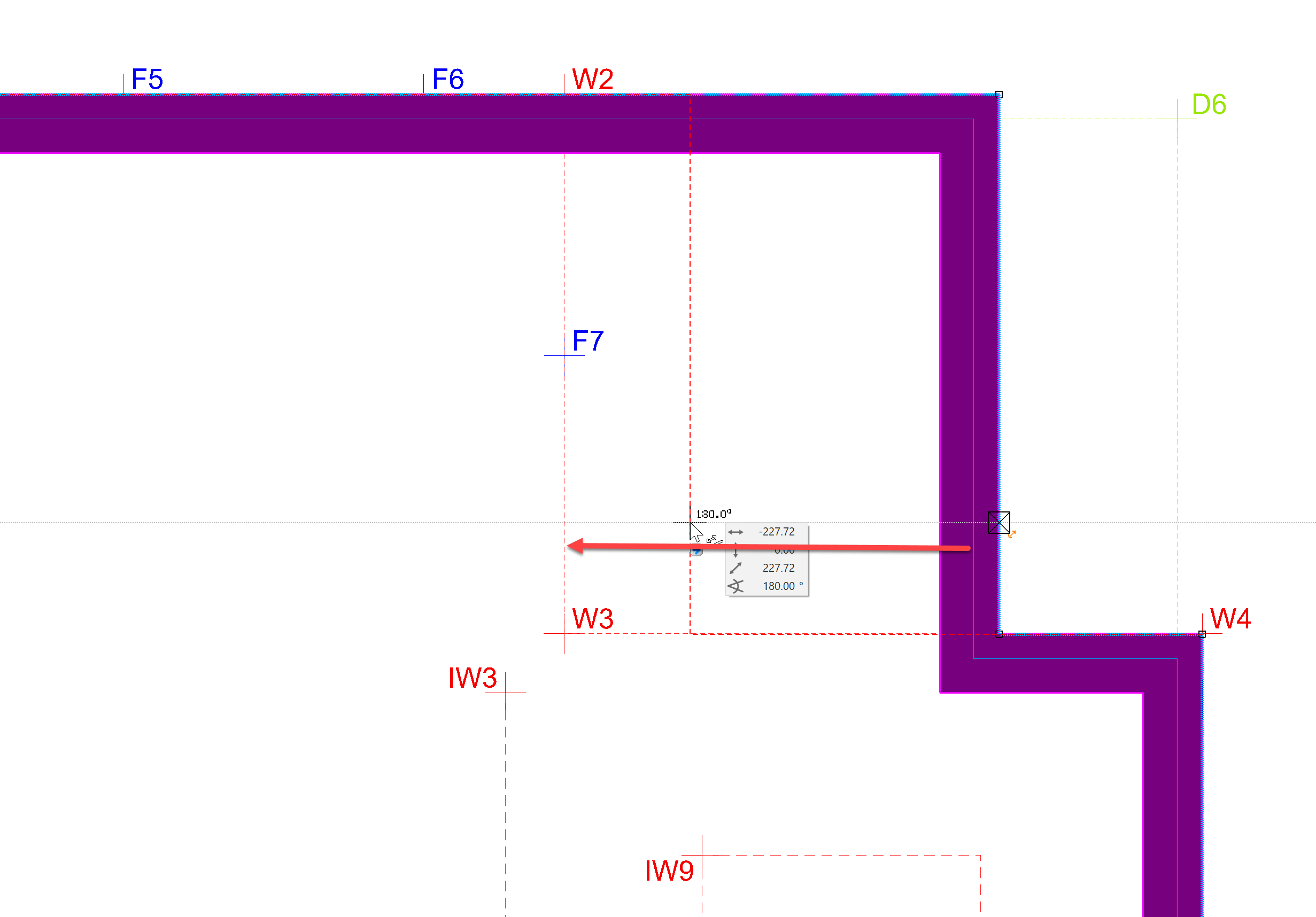
The wall should look like this:
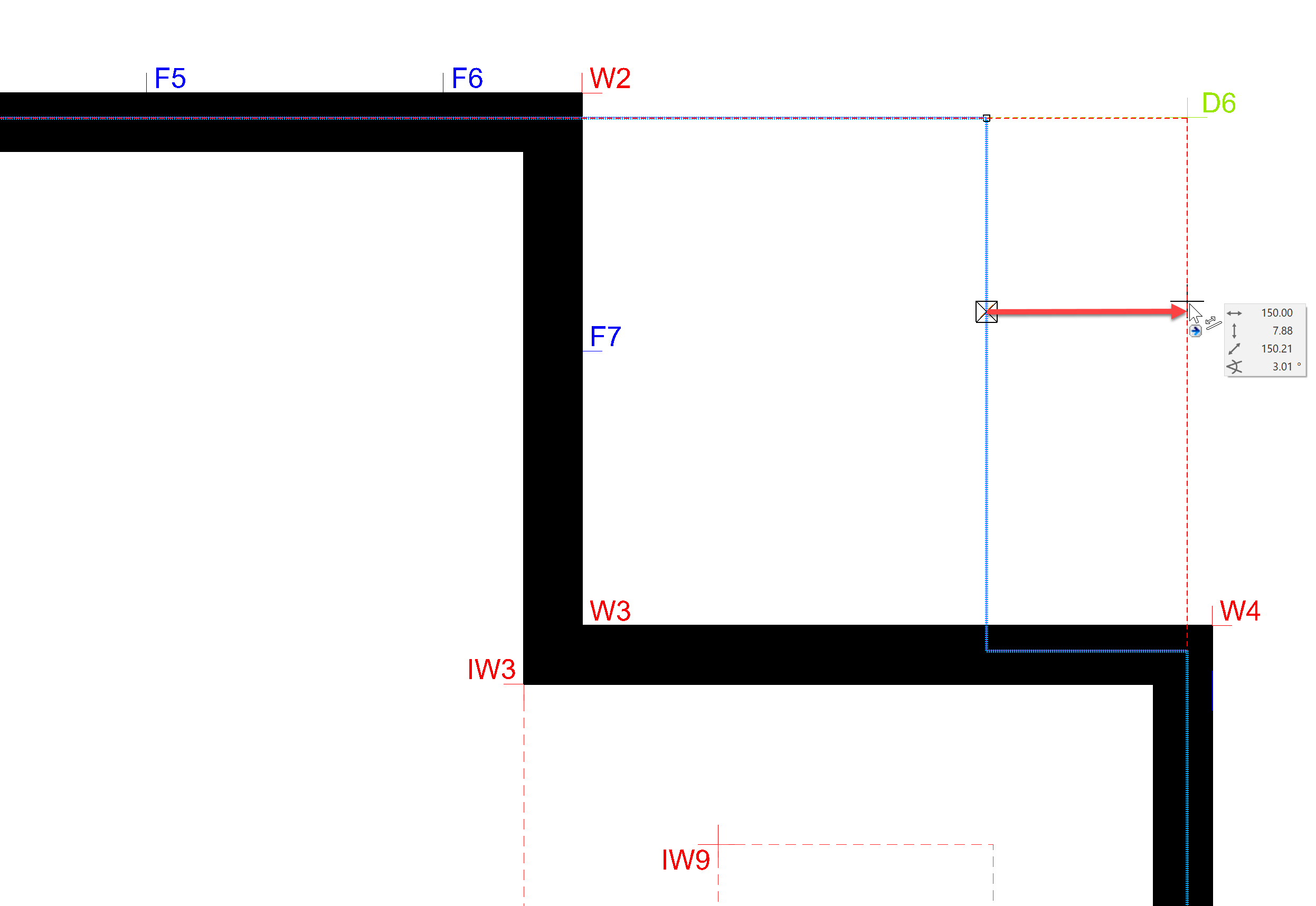
Now, the slab should be stretched outward. Select the contour of the slab and pull this, as shown, to Point D6.
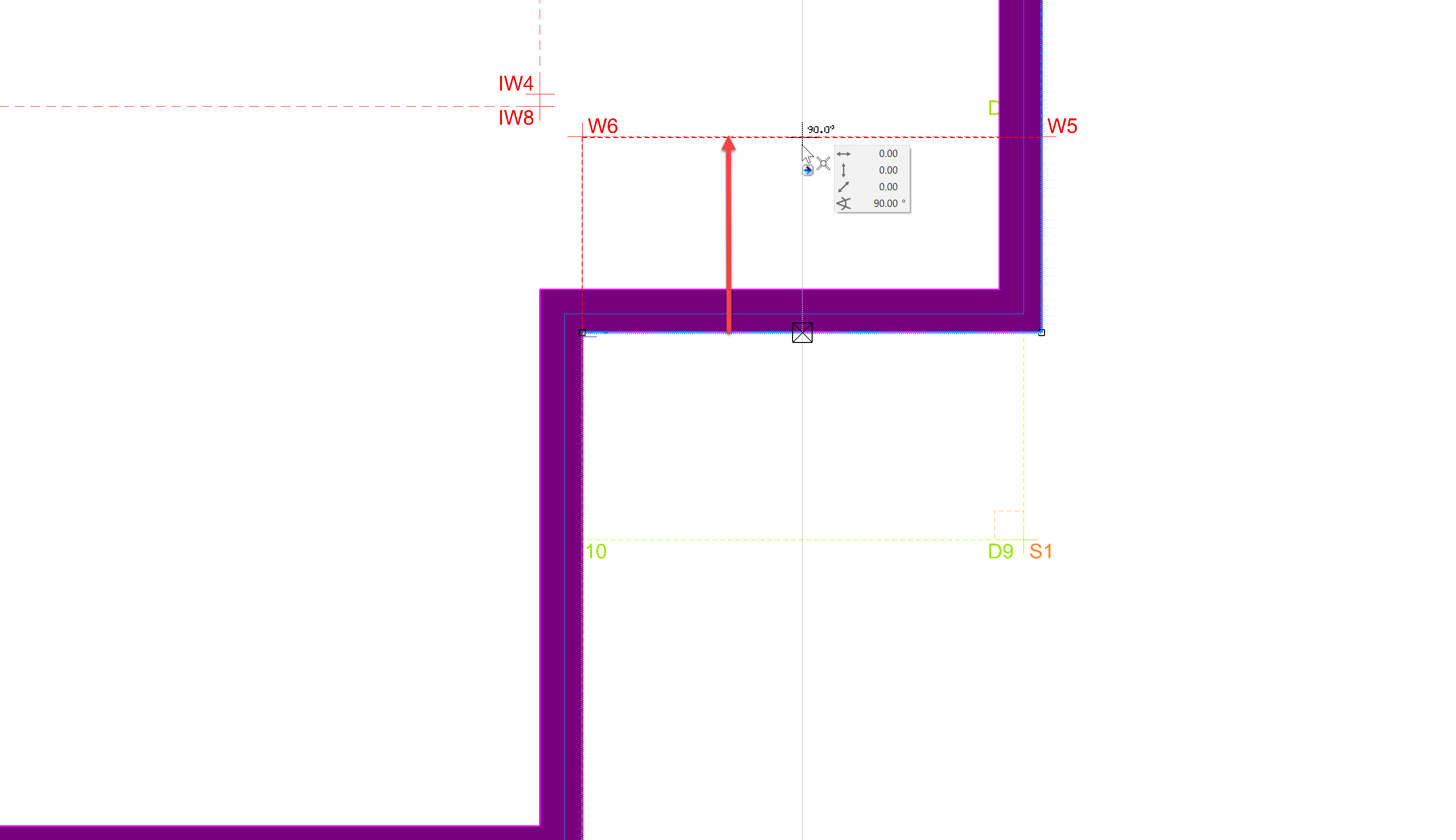
The wall and slabs of the front area should be adjusted similarly.
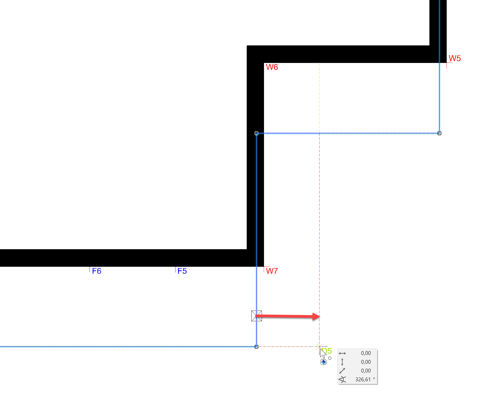
Pull the wall from the bottom to Point W6.
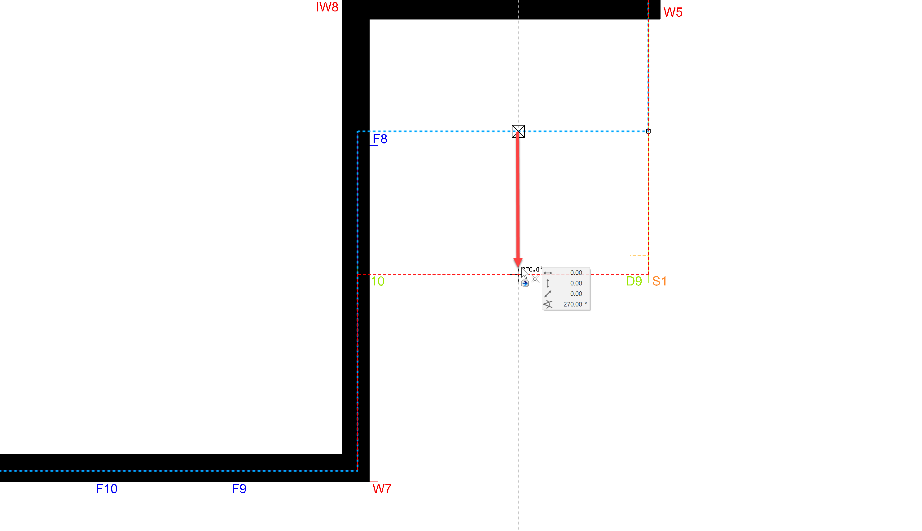
Pull the slab to Point D9.
In the next step, a balcony should be added to the front area. The storey slab will need a rectangle added for this. Select the contour of the slab as shown.
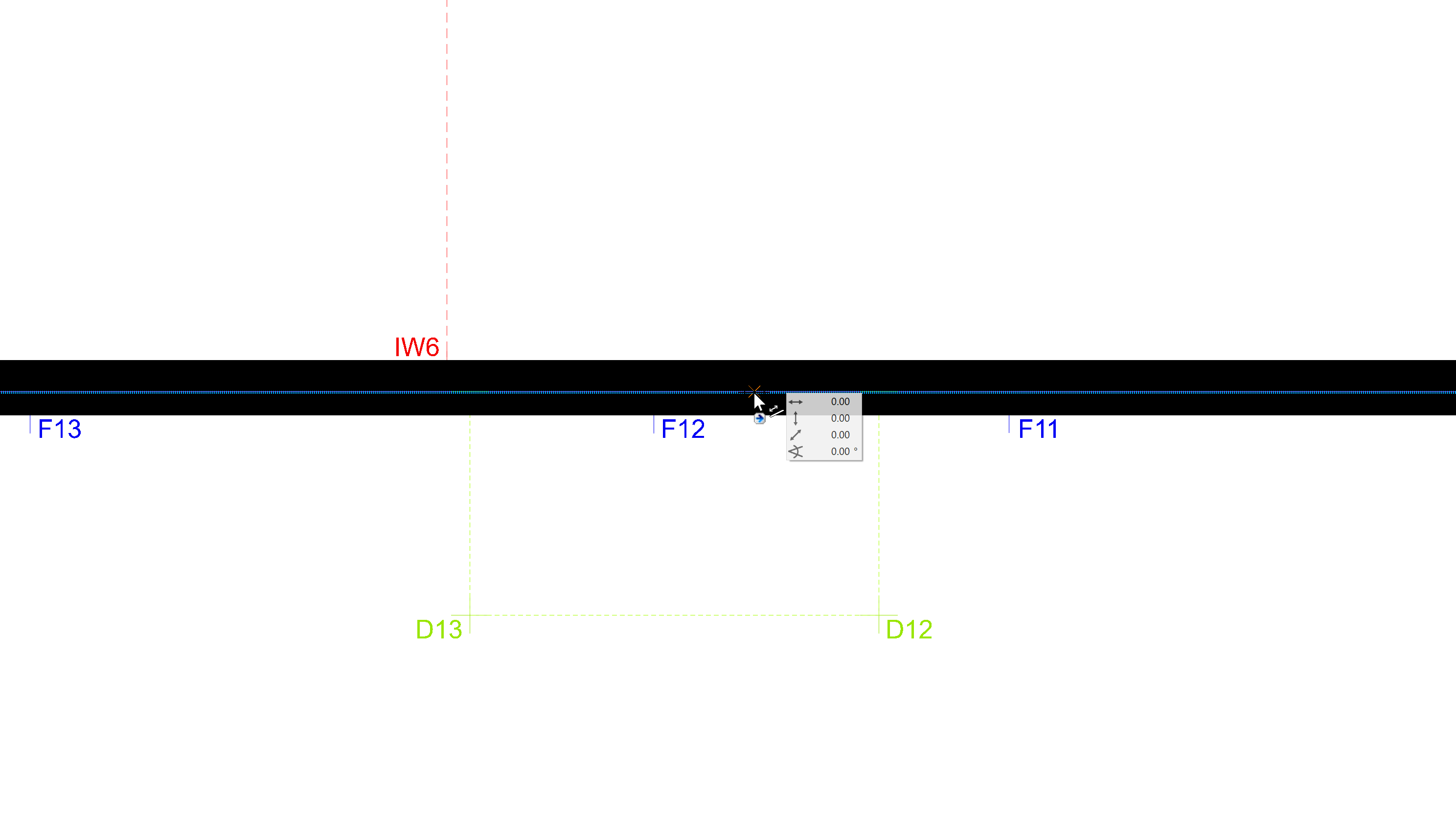
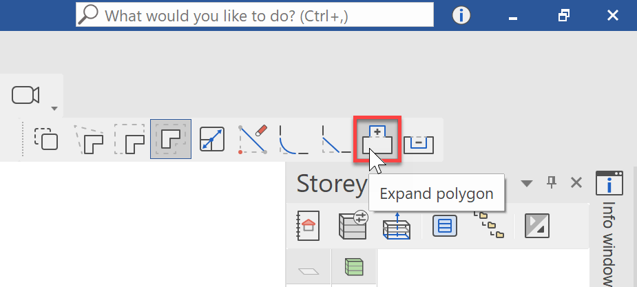
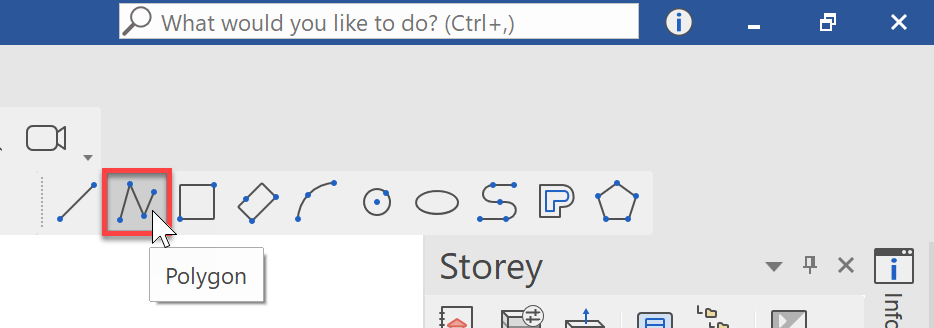
When the contour of the slab is selected and you move the mouse, the Move function is automatically started. For our project, we do not what to move the polygon, but rather extend it. To do this, select the Expand polygon function from the input assistant.
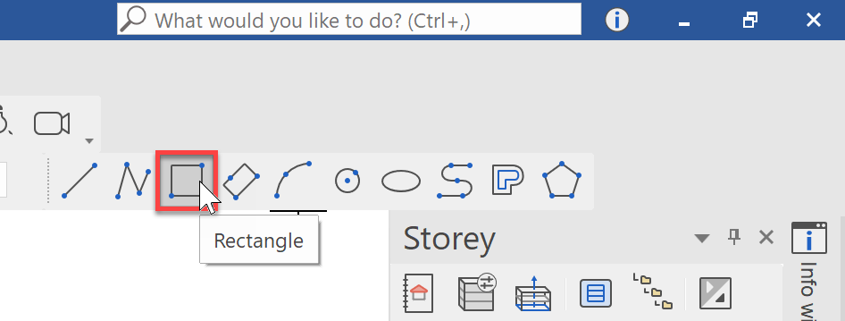
Now we can begin to enlarge the polygon with a polygonal chain of our choosing. But we already know that we need a rectangle and set this at the top right:
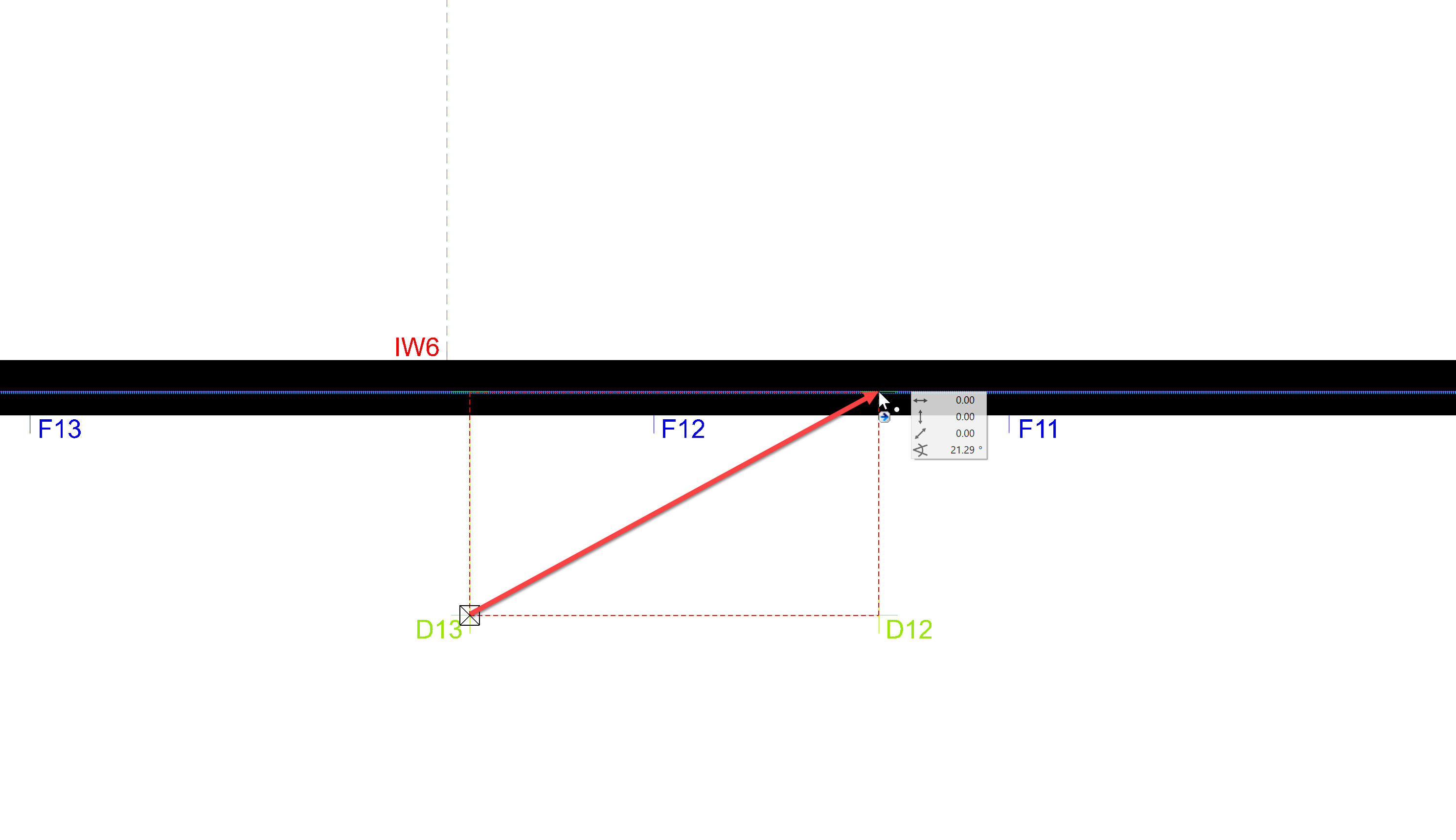
Now draw the rectangle diagonally from Point D13 to the edge of the slab at Point D11.
It is that simple to extend the storey slab to include the balcony. A second balcony should be built over the front corner of the building. This time, however, we will expand the polygon using a free polygon.
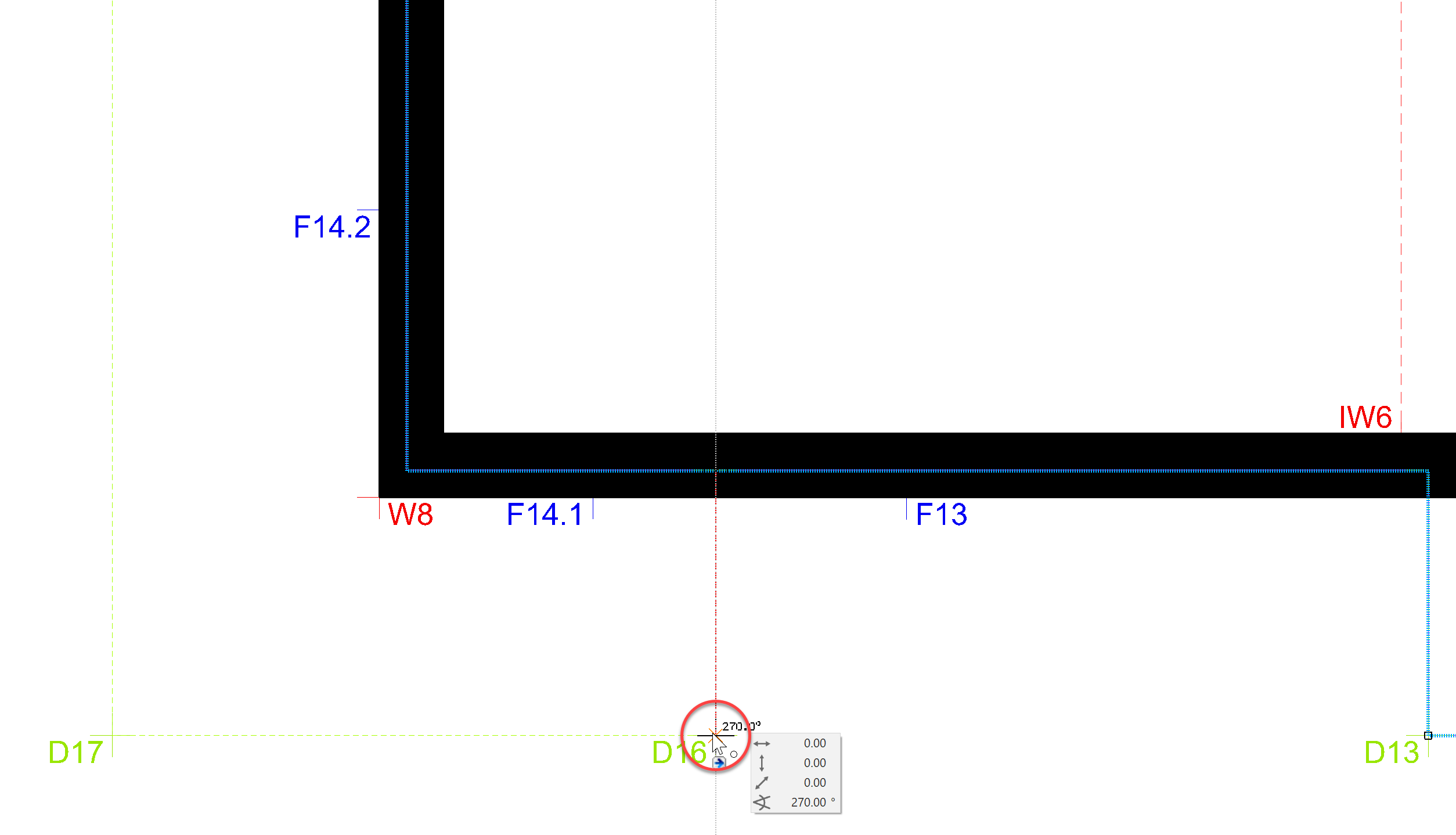
The slab should be drawn orthogonally to Point D16, then to Point D17, to Point D18 and finally to Point D19 to be reconnected to the existing Slab.
In order to capture the first connection point, we need the projection of Point D16 on the slab. To do this, move the mouse to *D16 and wait approx. 2 seconds until a temporary reference point appears. Now you can move orthogonally from the slab and capture the intersection. This is the first point of our polygon.
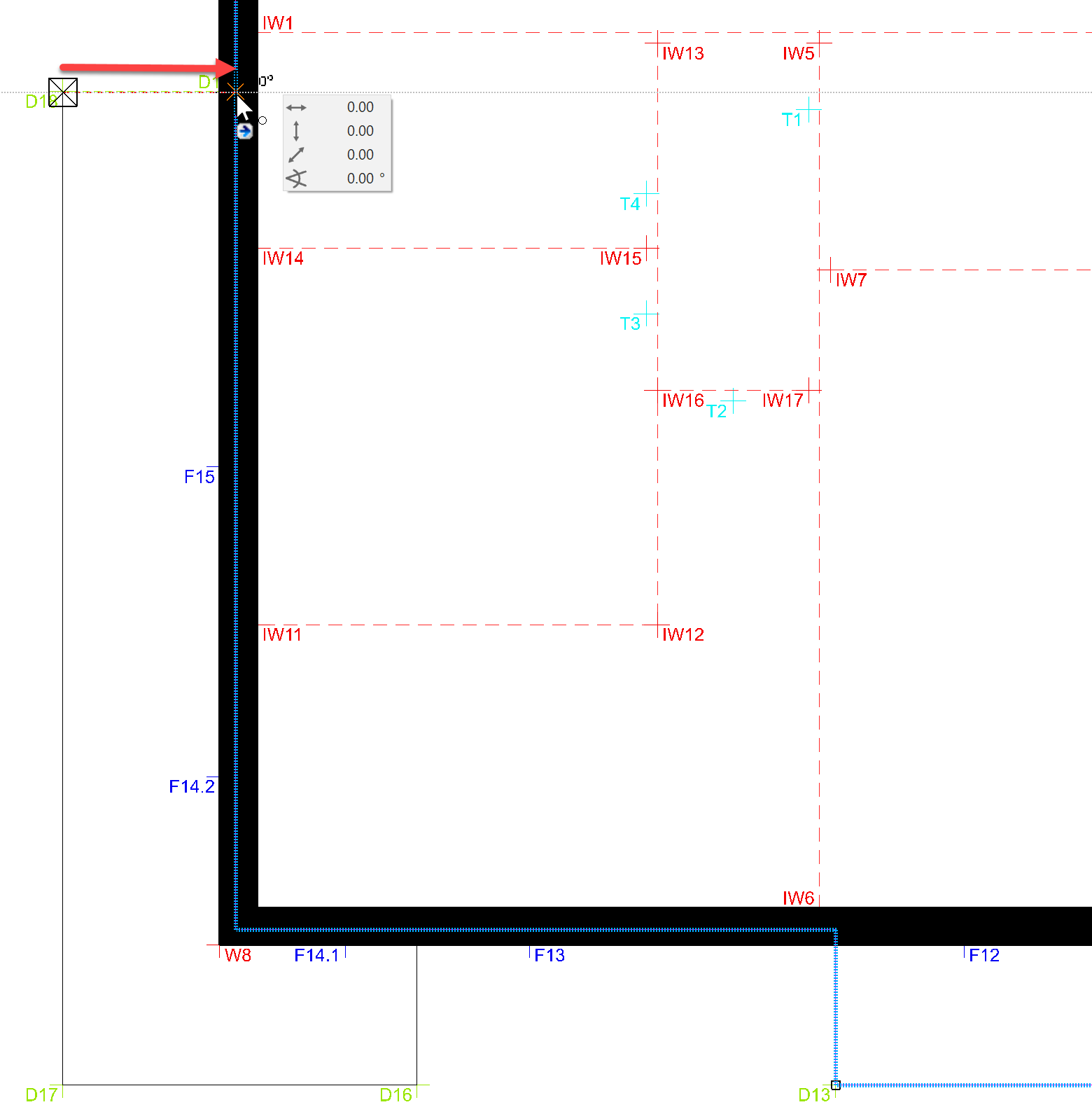
Follow the contour to D19, as described above.
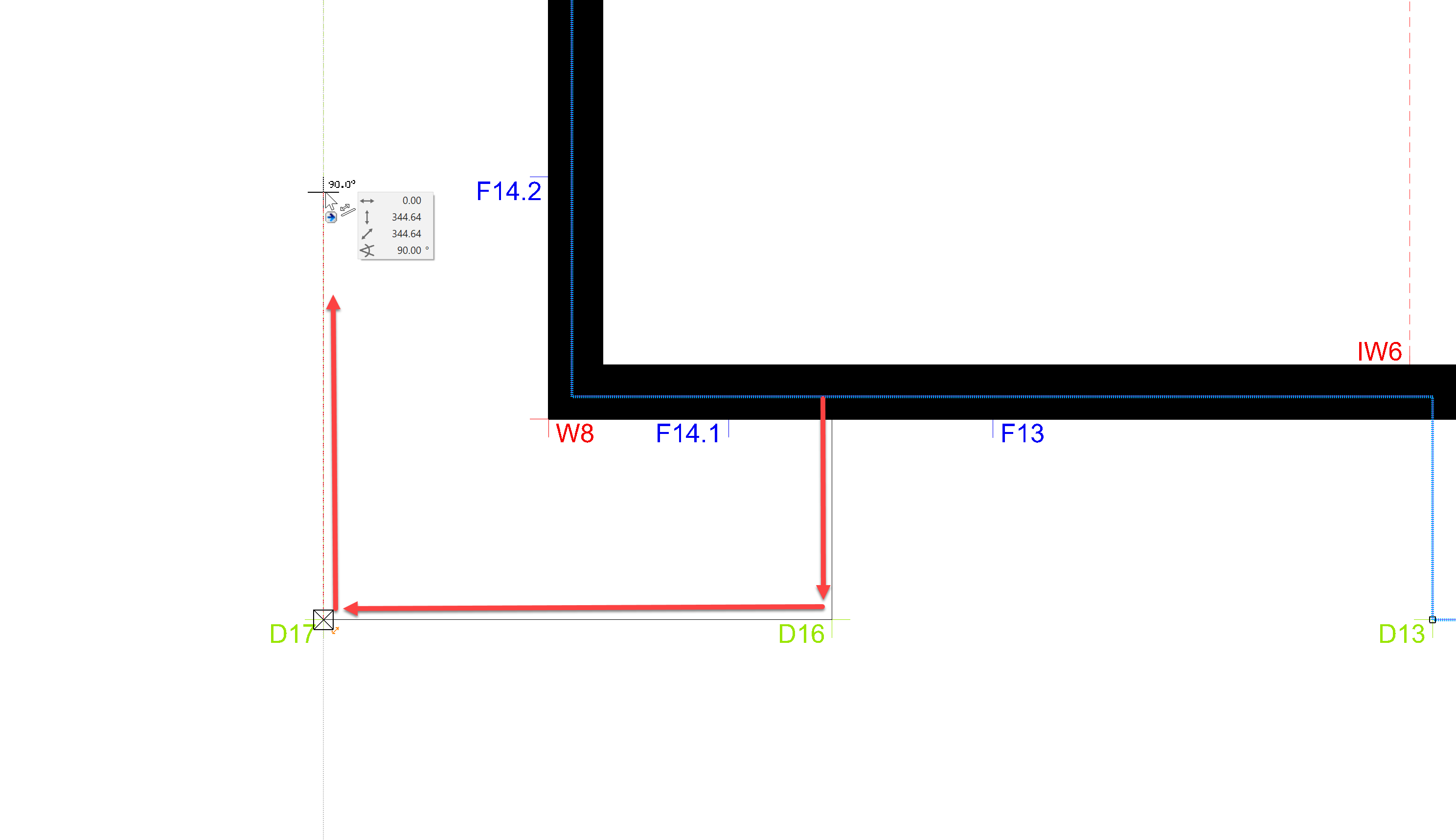
The polygon is closed with a double click on the final position.
The final balcony will be placed on the back side over the points D2 and D3. Use either a polygon or a rectangle.
Now your first floor should look like this:
Second floor
The second floor should be a copy of the first floor. We could now make the changes manually again, or we could use the practical copy function of ELITECAD and copy the walls and slabs to this storey.
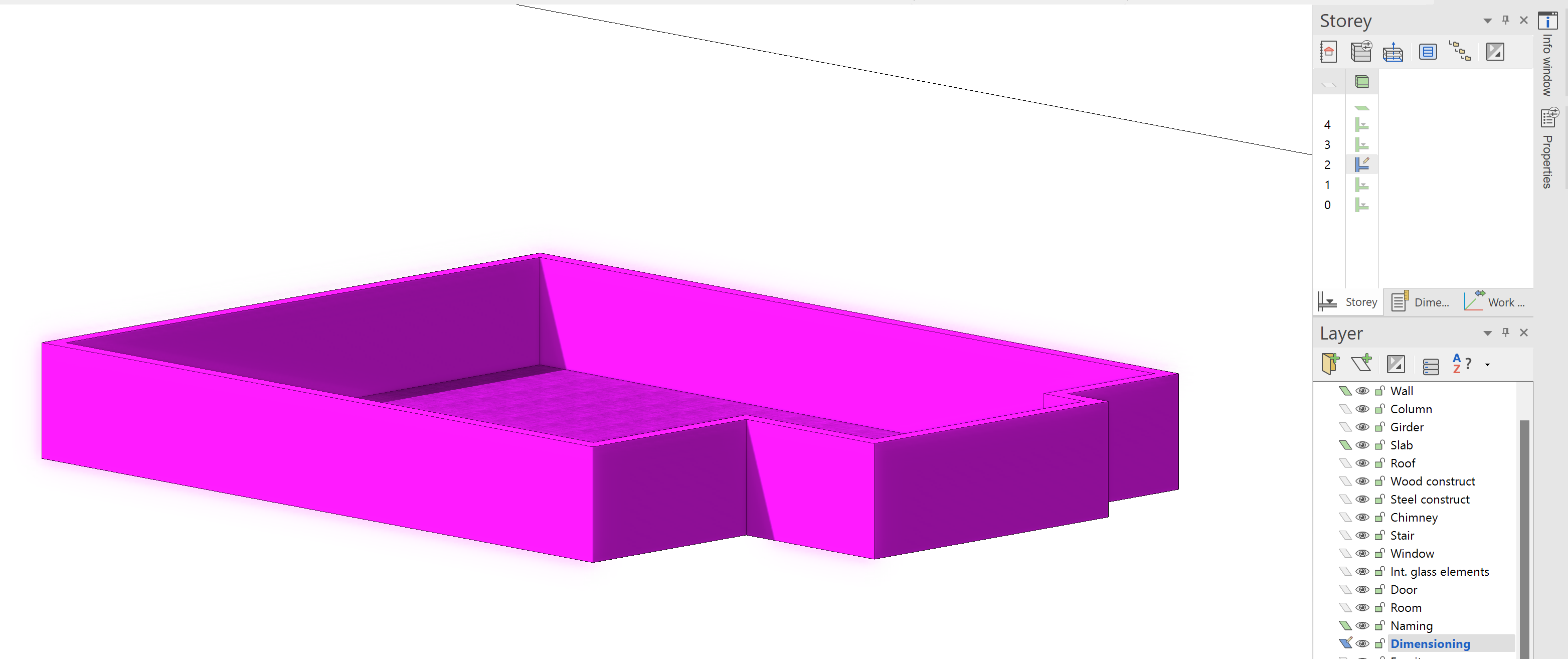
First, show the second floor alone, mark the wall and the slab and remove them with Del.
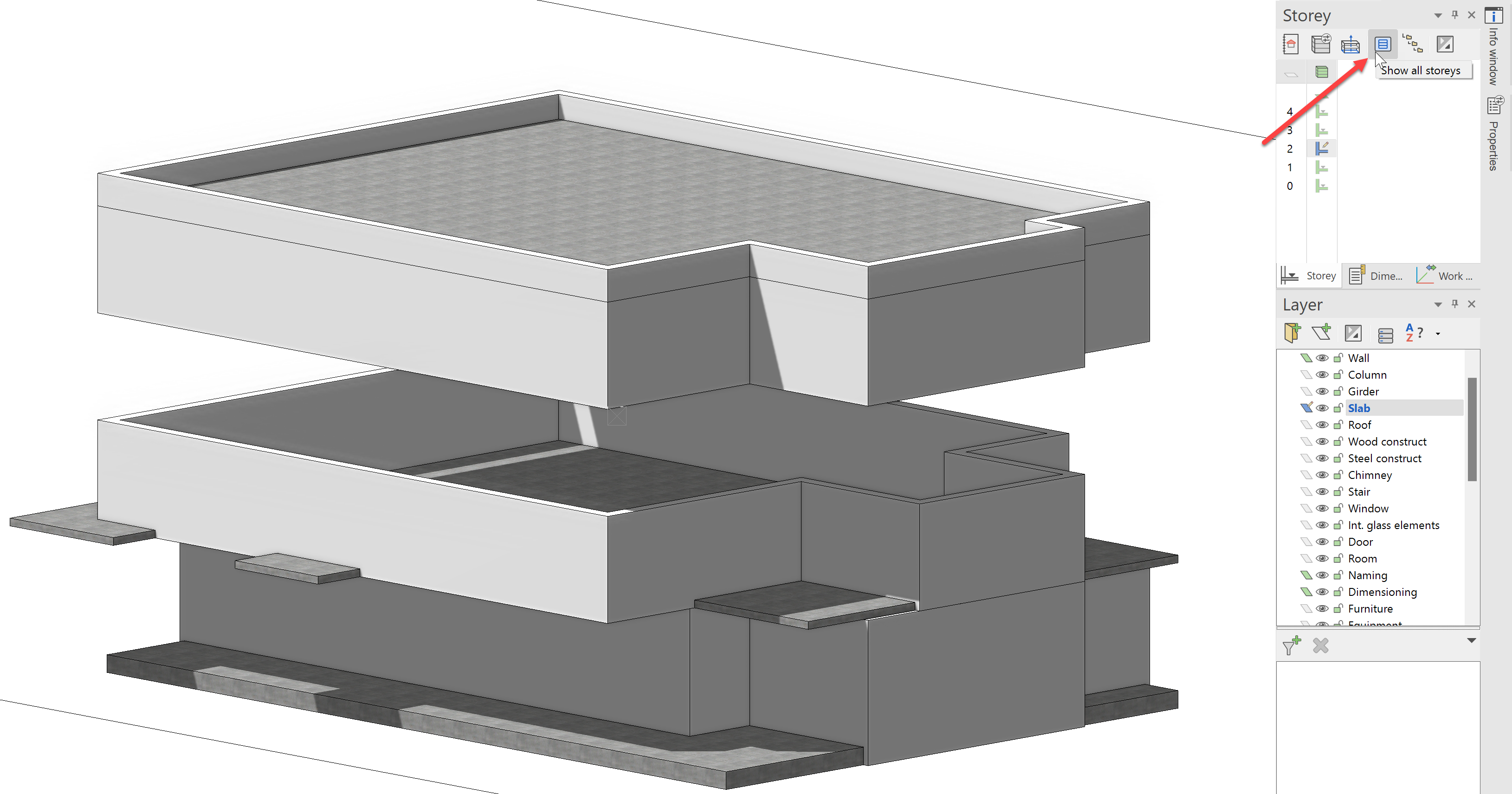
Afterwards, make the complete structure visible again with Show all storeys. The second floor should now be missing, as we deleted it in the last step.
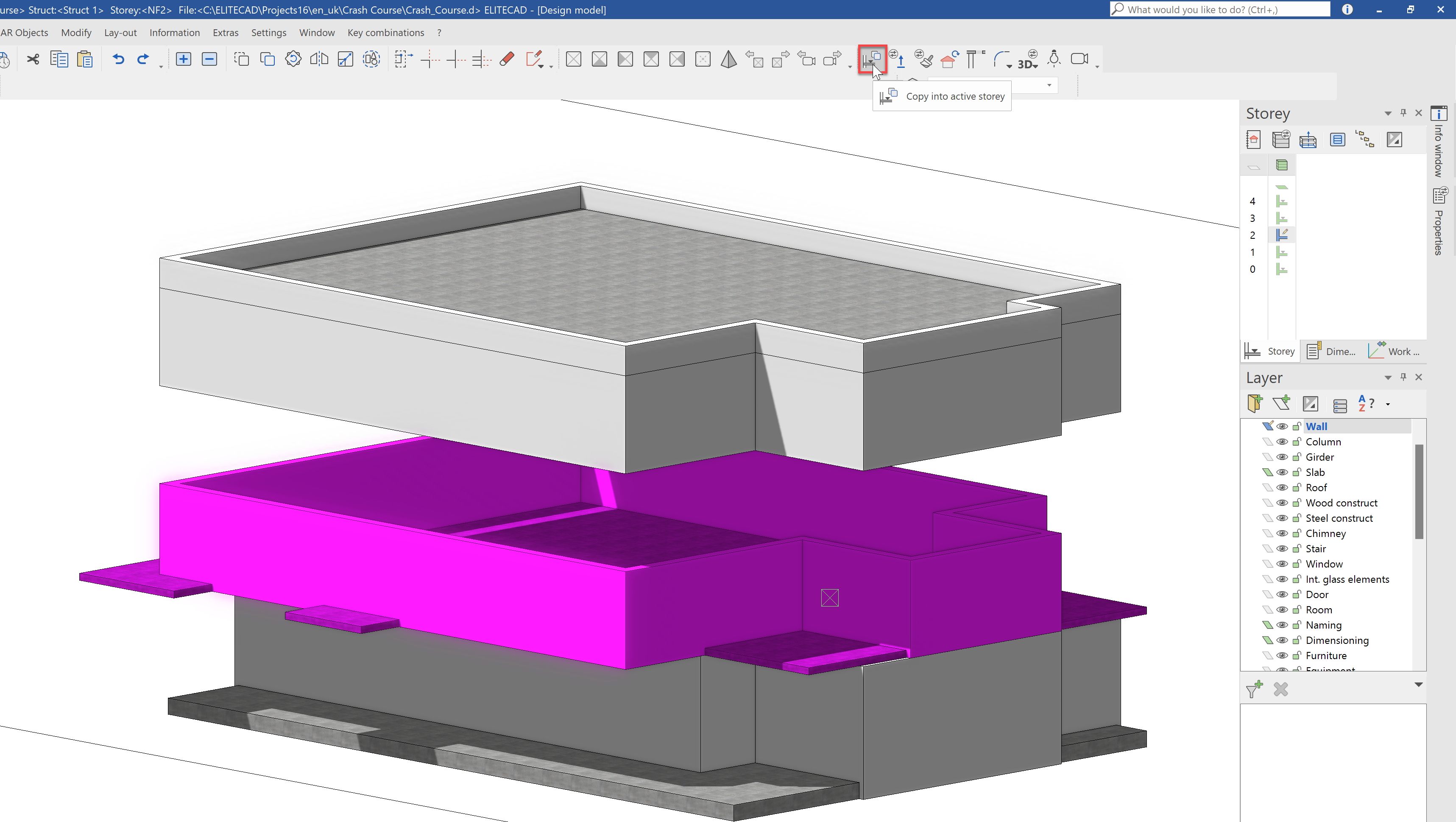
Make certain that the second floor is active. Select the slab and the wall of the first floor, then select the function; Copy into active storey. This function copies all selected construction elements into the currently active storey.
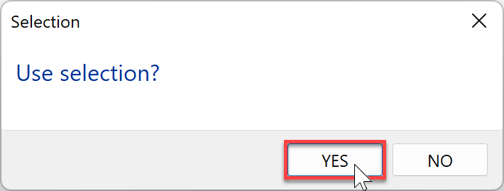
If the selection is correct, confirm the dialog with YES.
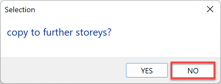
The selection can also be copied into further storeys. But as we have a penthouse apartment planned for the top floor, we will end the function with NO.
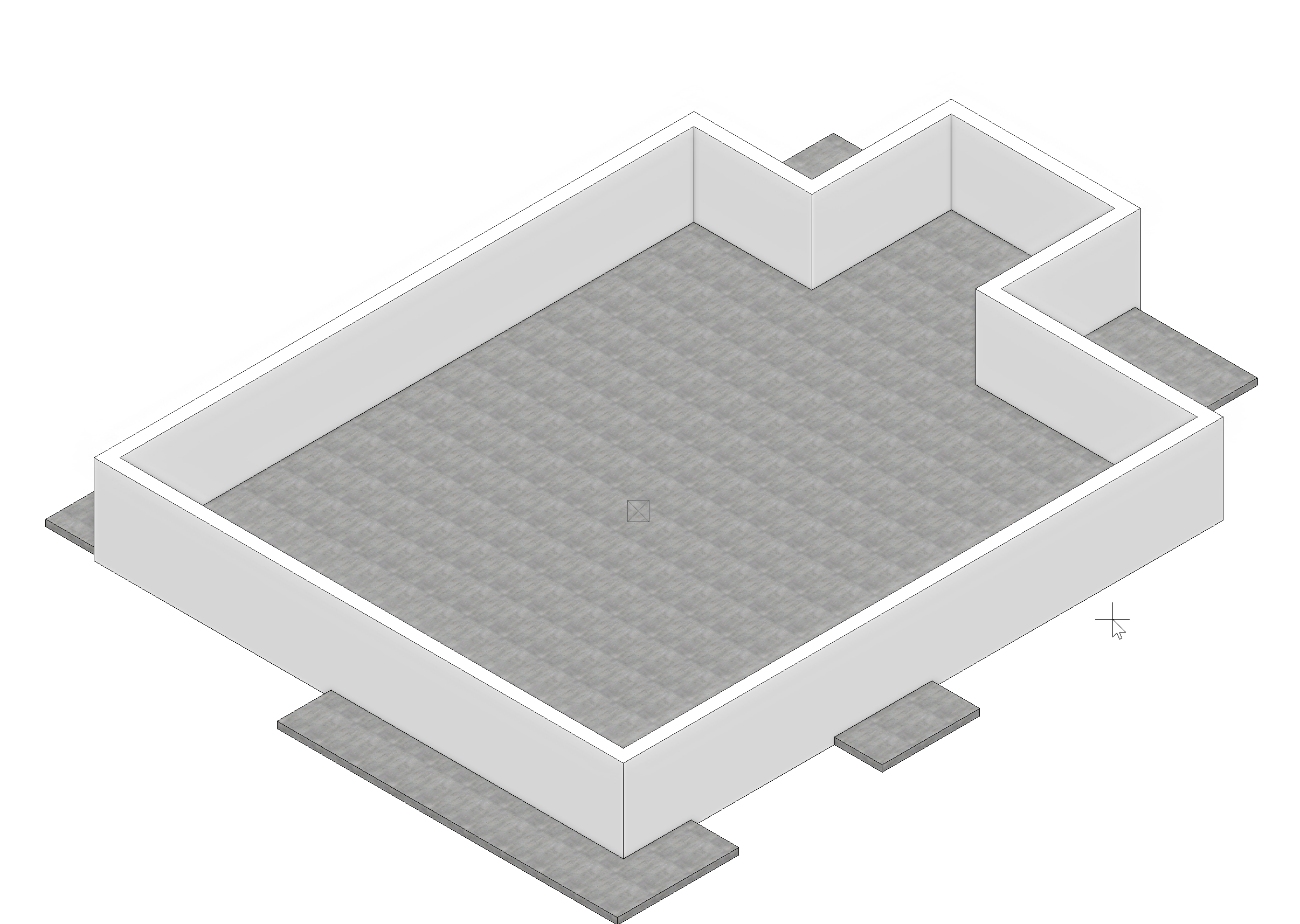
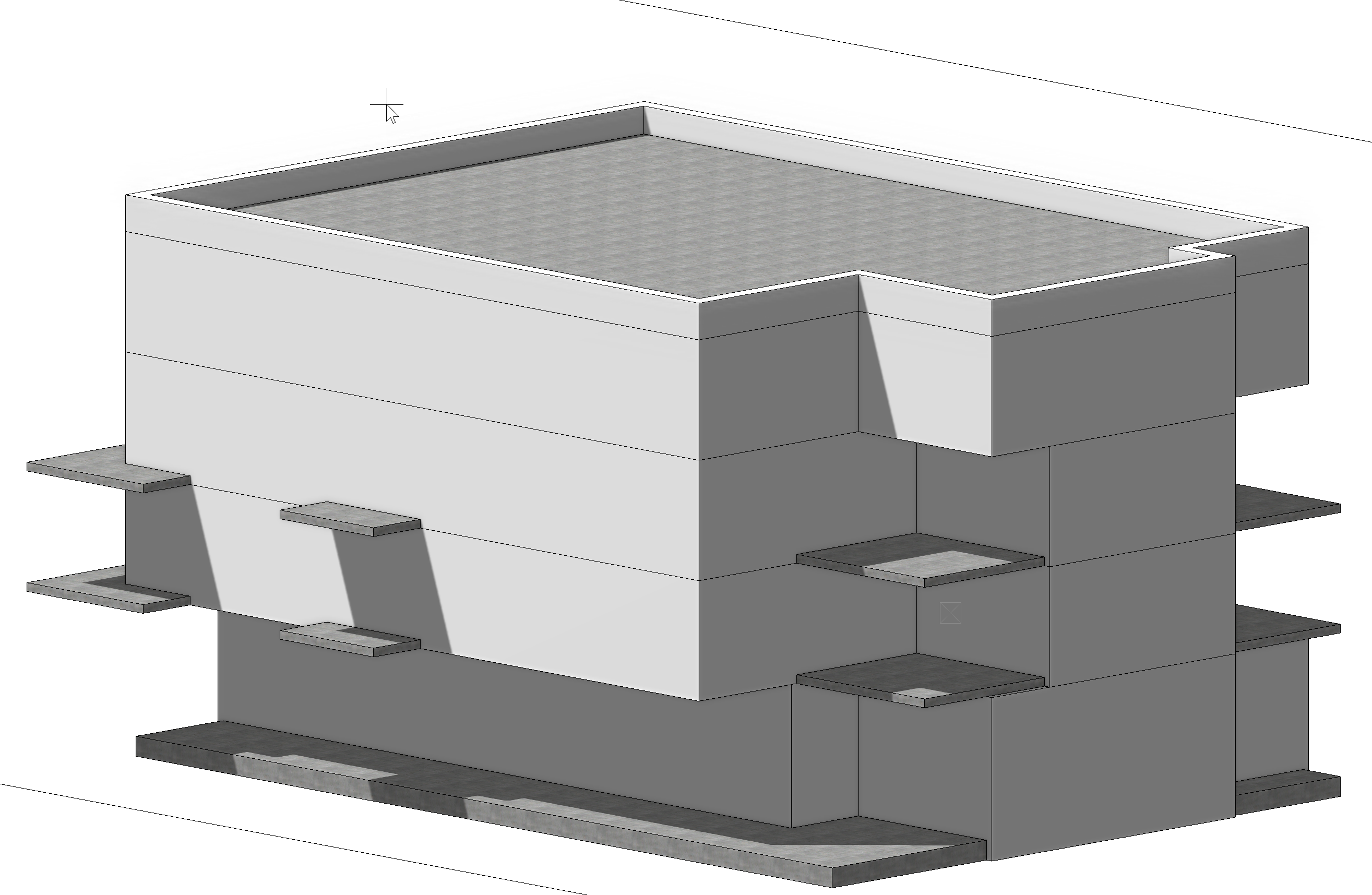
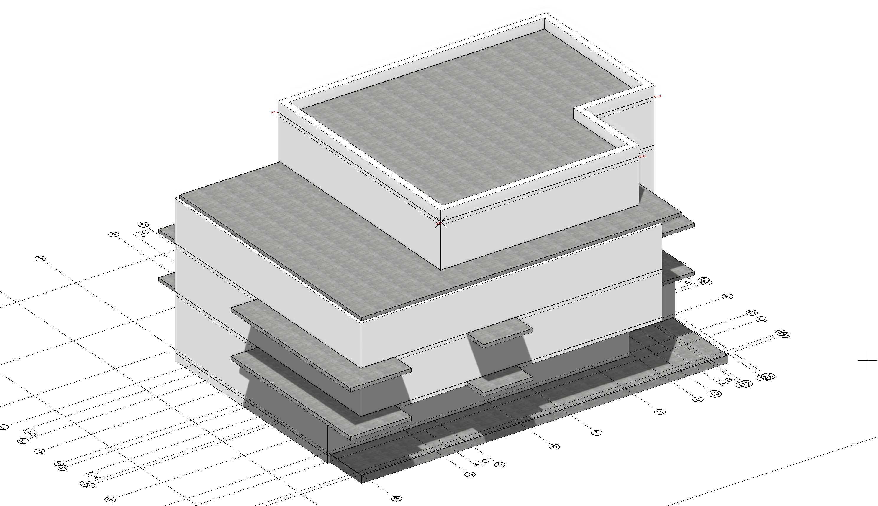
Our building model should look like this now:
Top floor
Now for the top floor, where a penthouse apartment will be constructed. Here, we will be working again in 3D on the entire model. If you would prefer to model in 2D, you can complete the steps also in the floor plan view.
First, we pull the wall of the front area back so that it is flush with the lower storeys.
Next, we must also pull the wall of the story above (the flat roof) backwards.
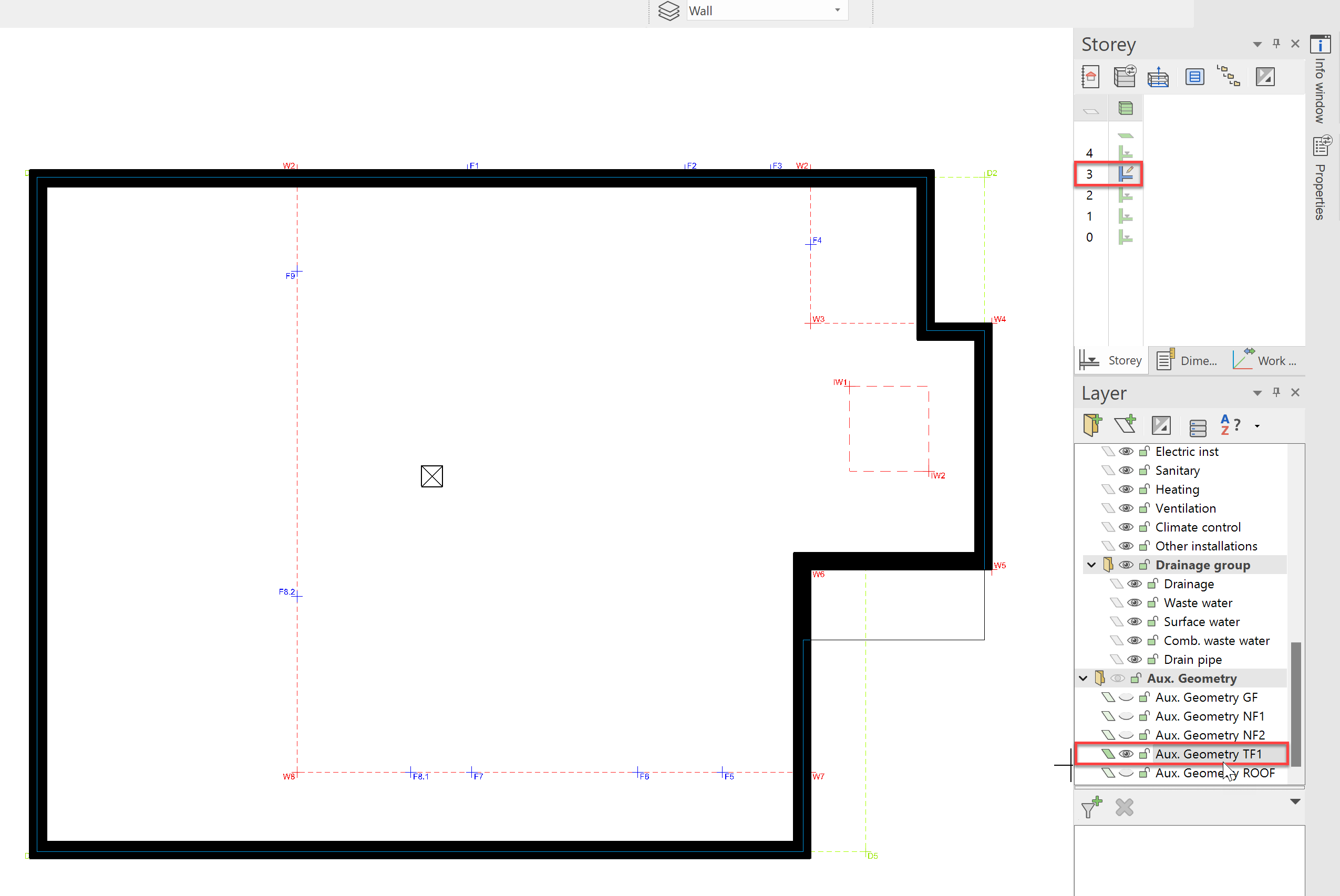
The roof terrace is our next modeling project. To do this, we will make the third floor visible alone and also make the Aux. Geometry TF1 visible. We will work in the floor plan view again for this. This is activated with Ctrl+D and Ctrl+Space.
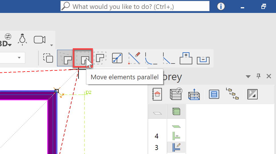
Firstly, both side walls should be moved inward. We could do this in 2 steps, or we could use the function; Move elements parallel. That this function, capture the wall at the bottom left.
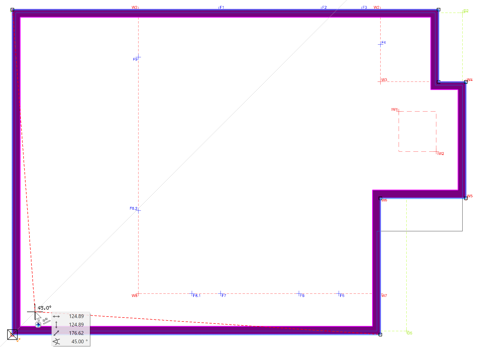
When you move the mouse, you will notice, that only the point is moved. But we also want to move the walls parallel. To do this, select the Move elements parallel function from the input assistant.
When you move the mouse in the direction of Point W8, the walls will also move parallel. Click on W8 to confirm the new position of the wall.
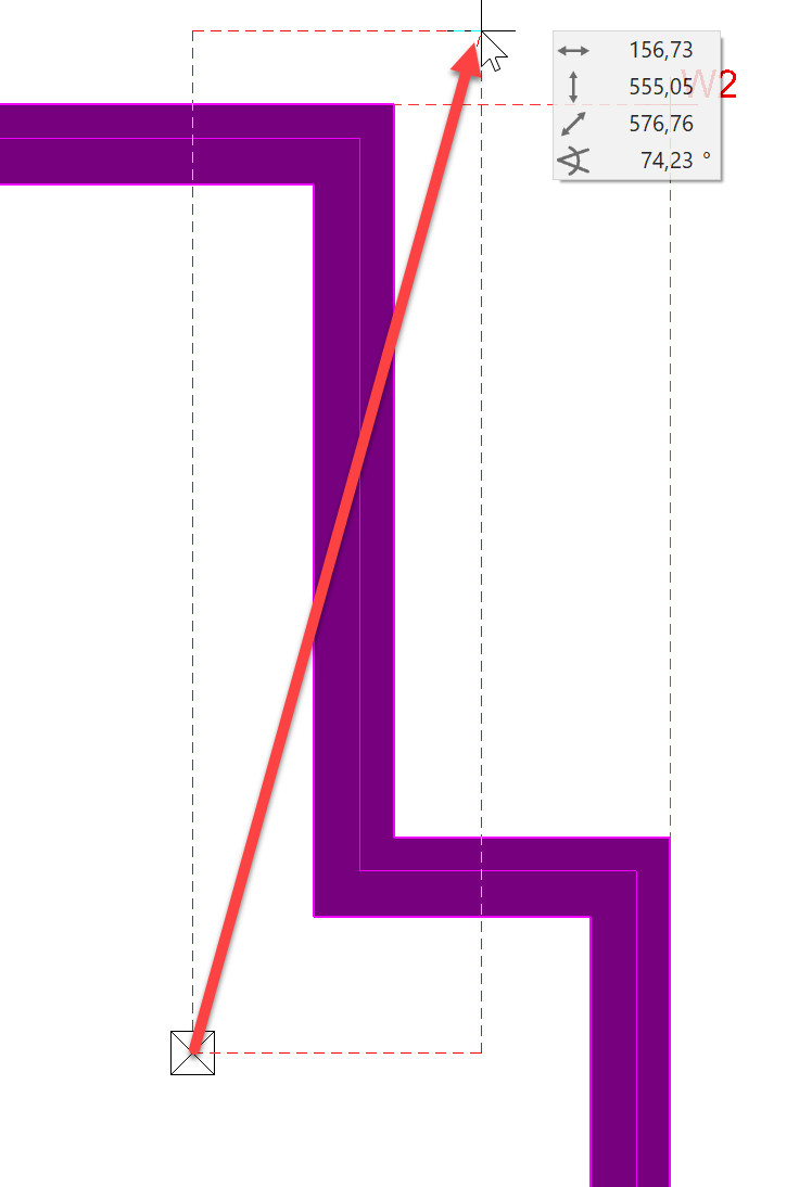
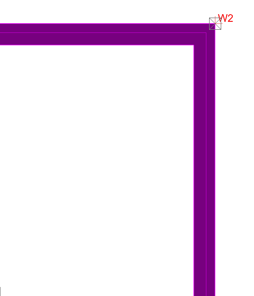
For the next step, the upper right wall should be stretched to Point W2.
Stretch the slab to Point D2 by selecting the outer contour.
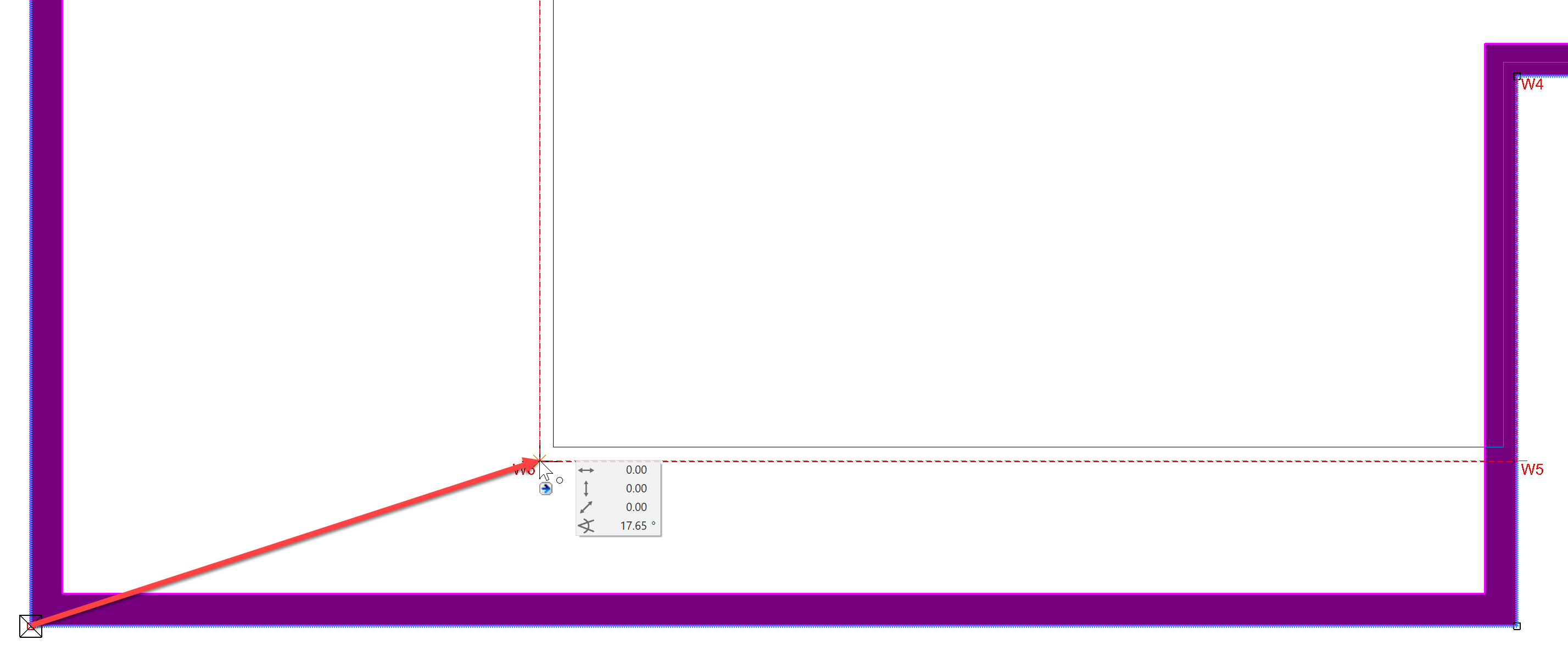
In the front area, we pull the slab outwards to Point D5.
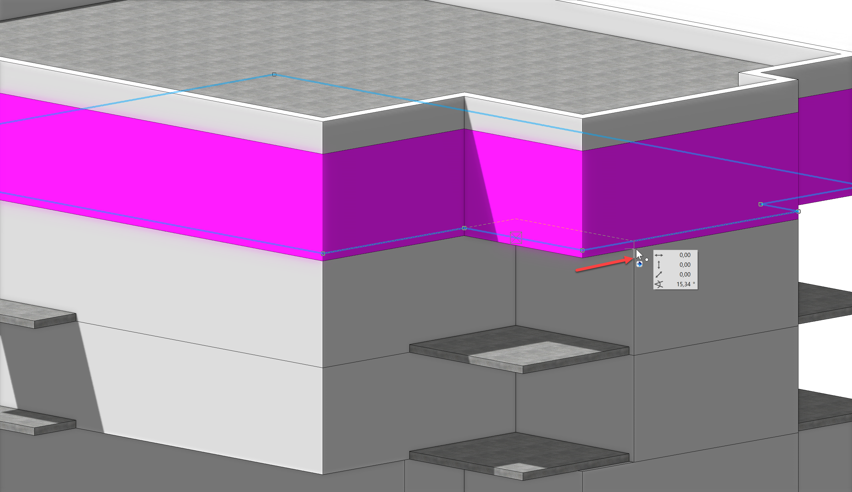
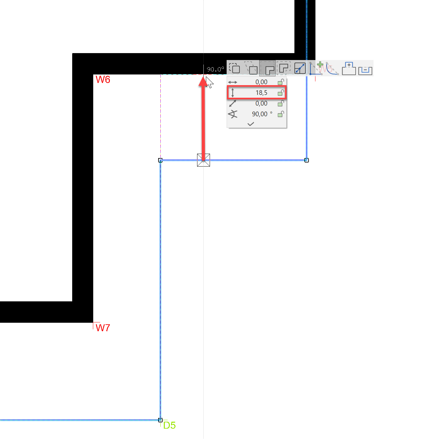
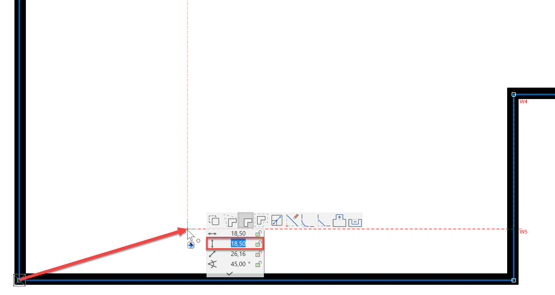
Finally, the slab should be pulled inwards. Since a brick wall with 18.5 cm of thermal insulation will be installed later, the slabs should be moved further inwards by the corresponding thickness of the insulation. First select the contour of the slab and pull it up to the outer edge of the wall.
Prior to confirming, wait approx. 2 seconds and them open the input assistant using the Tab key. Now you can enter a value by which you want to move the slab even further. Enter the value 18.5 here and confirm with Enter.
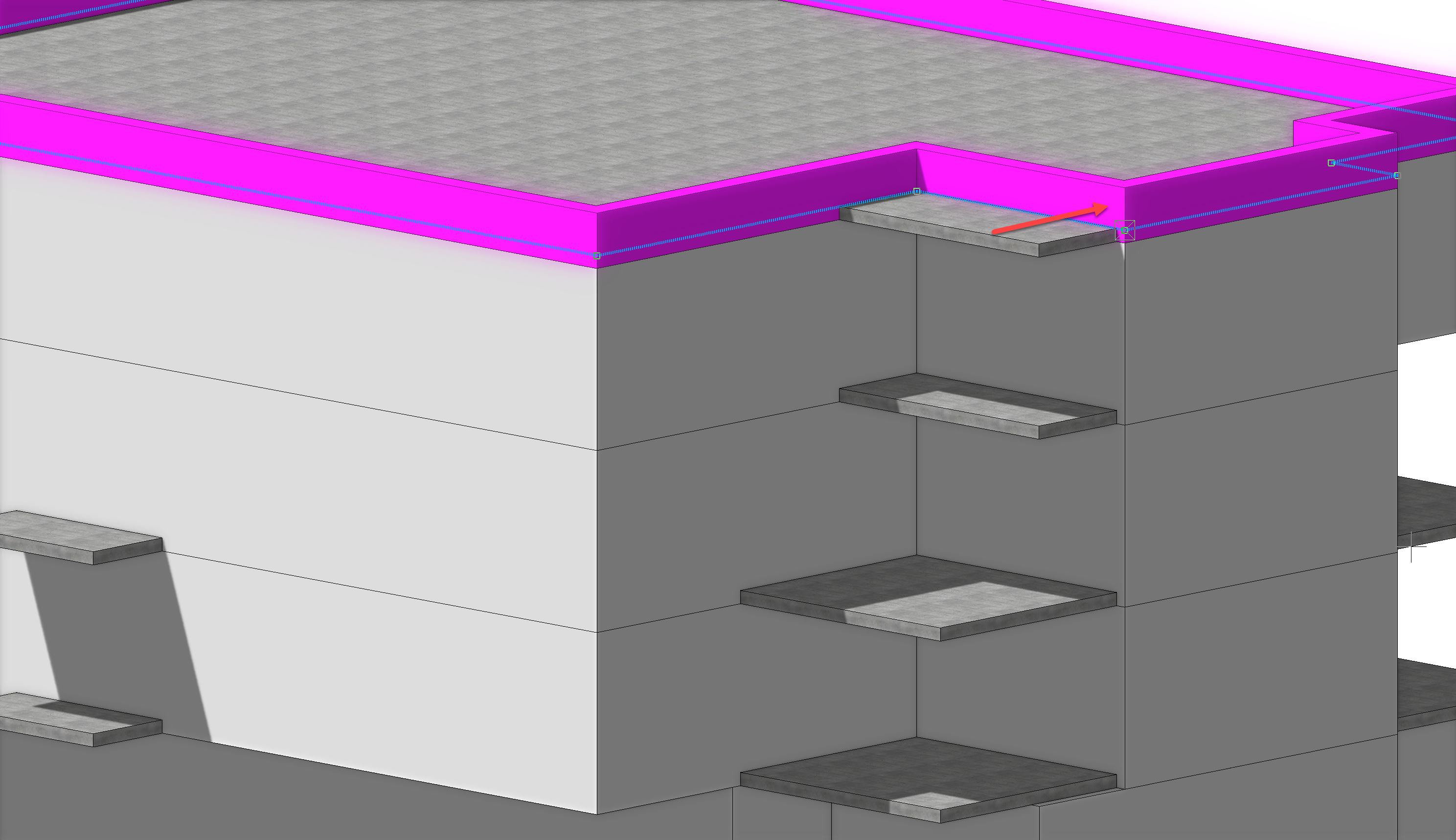
The result should look like this: If we later change the wall structure to a multi-layer wall with thermal insulation, the insulation will also enclose the slab.
Roof
Finally, we take care of the roof. Since our building is a flat-roofed house, we have defined it as its own storey.
Next, show the roof alone and make the layer Aux. Geometry ROOF (Roof top view) As with the previous storey, we first pull the slab flush against the wall and then 18.5 cm inwards so that it lies within the planned insulation.
In ELITECAD, there are a variety of way to execute every task. If the basic function has been completed, several work steps can also be carried out with one function . CHECK TRANSLATION AND ORIGINAL TEXT An example of this is the stretch function. Instead of moving slabs and walls in two steps, this can also be done across construction elements by means of the stretch function.
To do this, select the wall and slab using the rectangle selection from the bottom right to the top left as shown below.
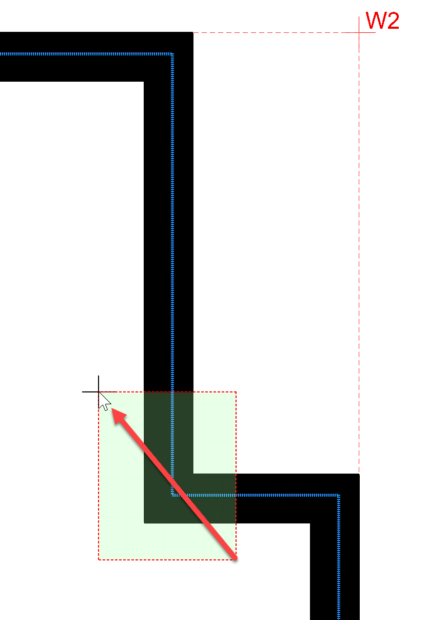
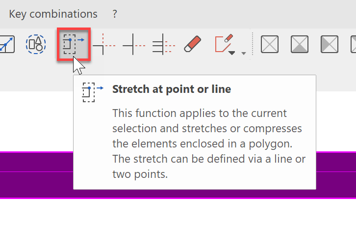
Now from the menu bar, start the function; Stretch at point or line
In order for the function to know how the geometry should be changed, several inputs are necessary. First, a point on the original geometry is queried.
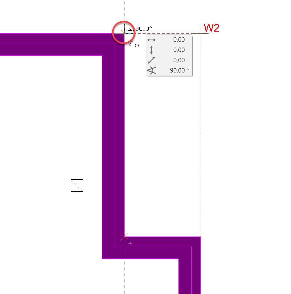
Then a position, to which the first point should be moved. In our case, this is W2.
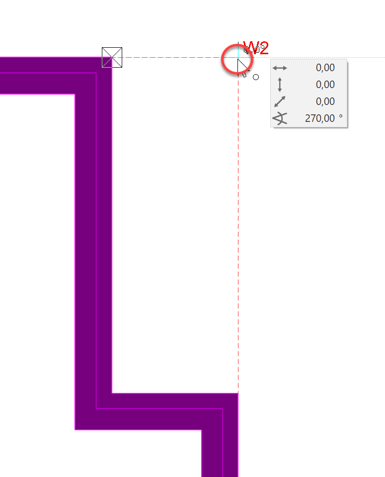
Finally, we must specify the area to be stretched. This is done by rectangle selection from the bottom left to the top right. Select the area as specified and complete with a double click:
As a result, we see that not only the wall, but also the slab was stretched accordingly.
The stretch function is a central element in ELITECAD, because it also allows stretching in 3D over several storeys. This makes it possible, for example, to adapt walls and slabs over several storeys with just one step.
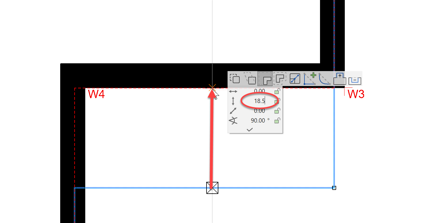
Similar to the top floor, the roof slab should also be moved at Point W6 to incl. a 18.5 cm offset. This offset can be re-drawn using the input assistant opened with the Tab key.
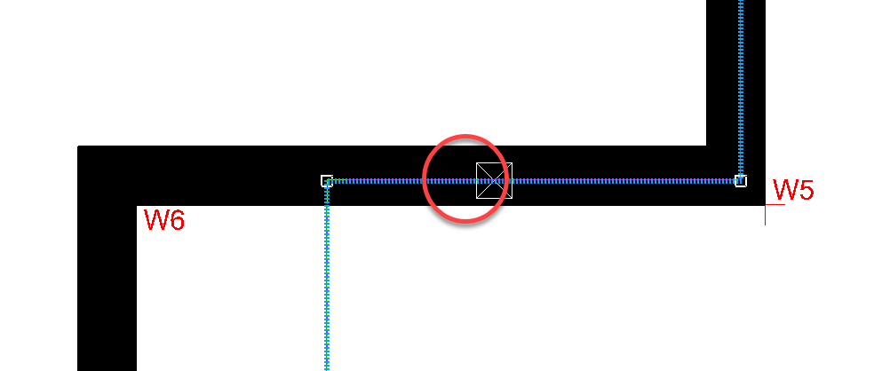
Finally, we pull the wall to Point W6.
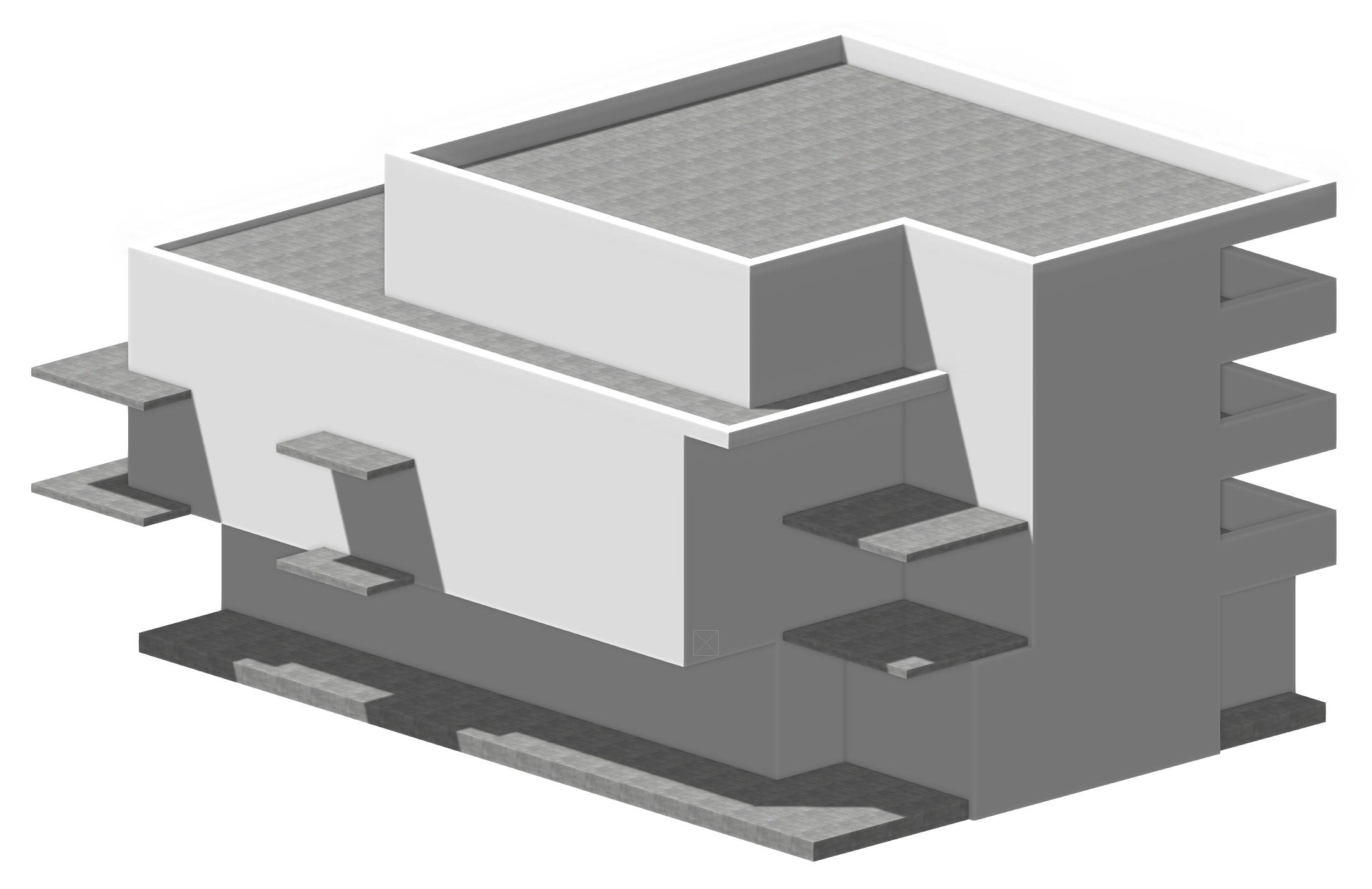
Your structure should now look like this:
Parapet walls
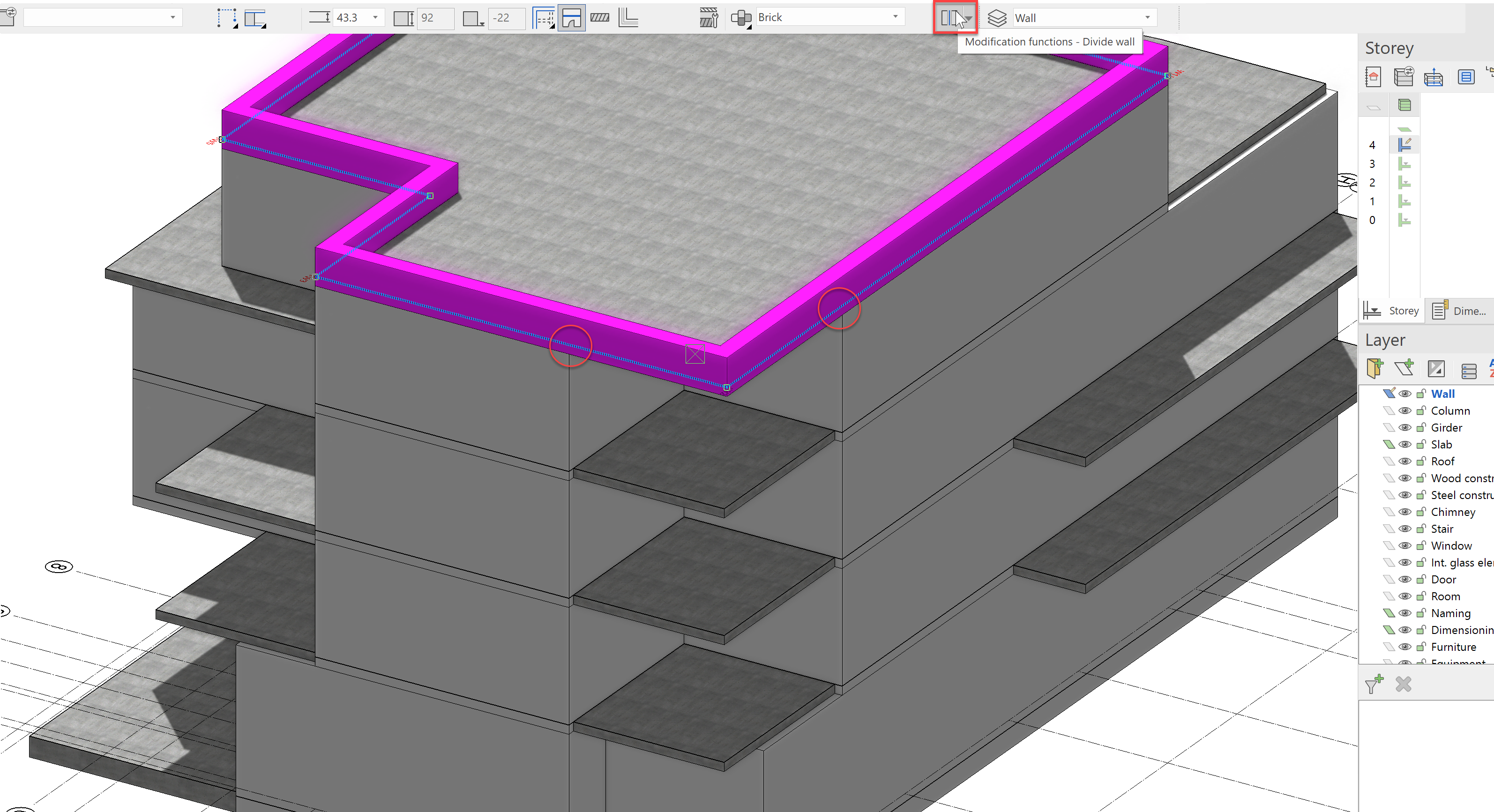
Next, we should create guard rails for the balconies. There are many possibilities how to implement this. In our case, we will do this with the functions; Divide wall and Copy.
First, select the wall of the roof and start the Divide wall function from the property bar and then enter the two division points as shown here:
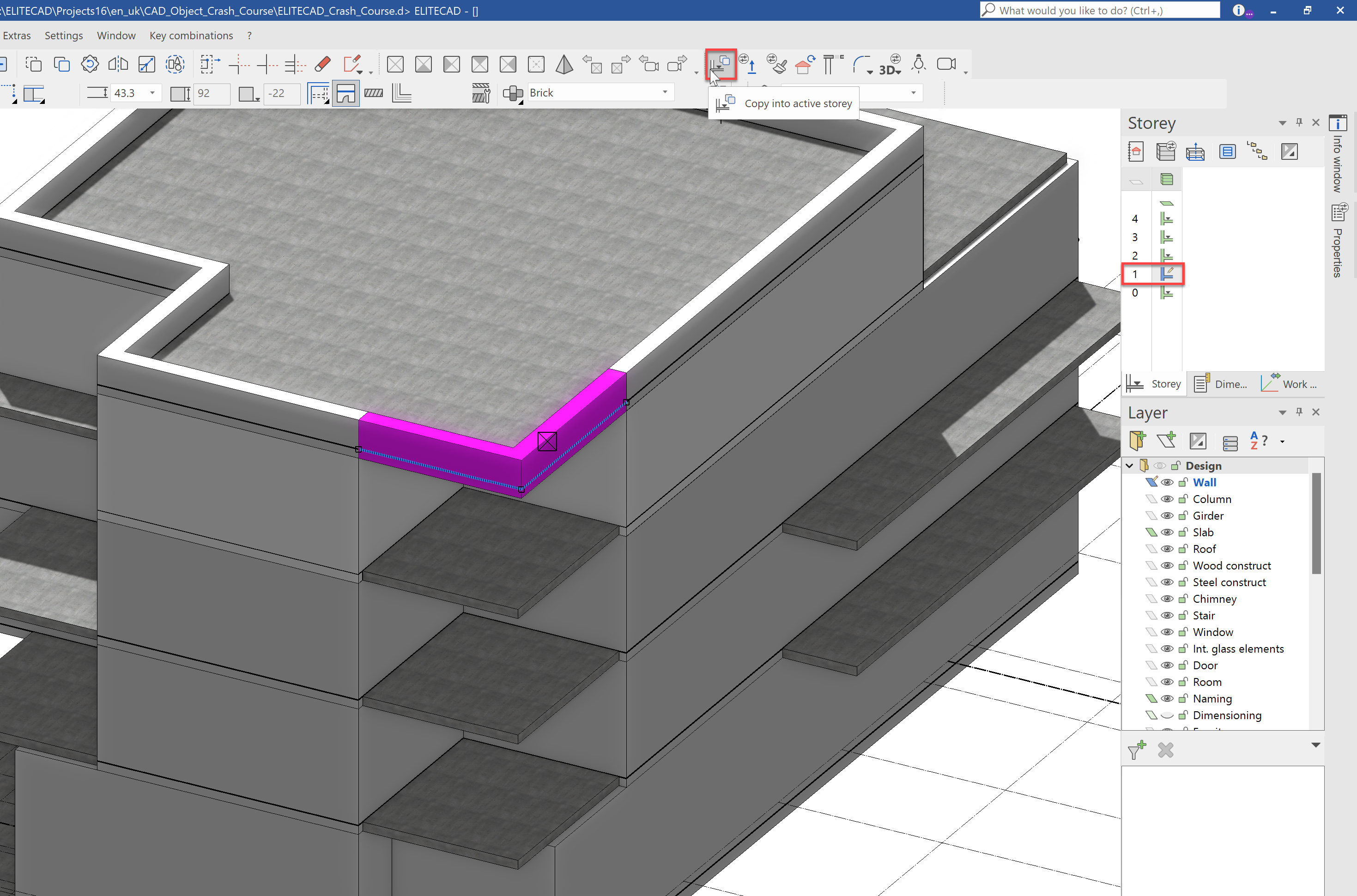
Now activate the first floor, select the divided wall of the roof and use the Copy into active storey function. Now we see that the wall is room-high. We will not copy this into other storeys yet, so end the function.
Why did that work like that? Although the wall of the roof appears to be a parapet wall, it is actually a regular wall with a height reference to the underside of the slab of the storey. This is why, in the project settings, we entered, that the roof only has a height of 92 cm. Should the wall, as we have done here, be copied into a lower storey, it will automatically align to the storey height. We must only change it to a parapet wall.
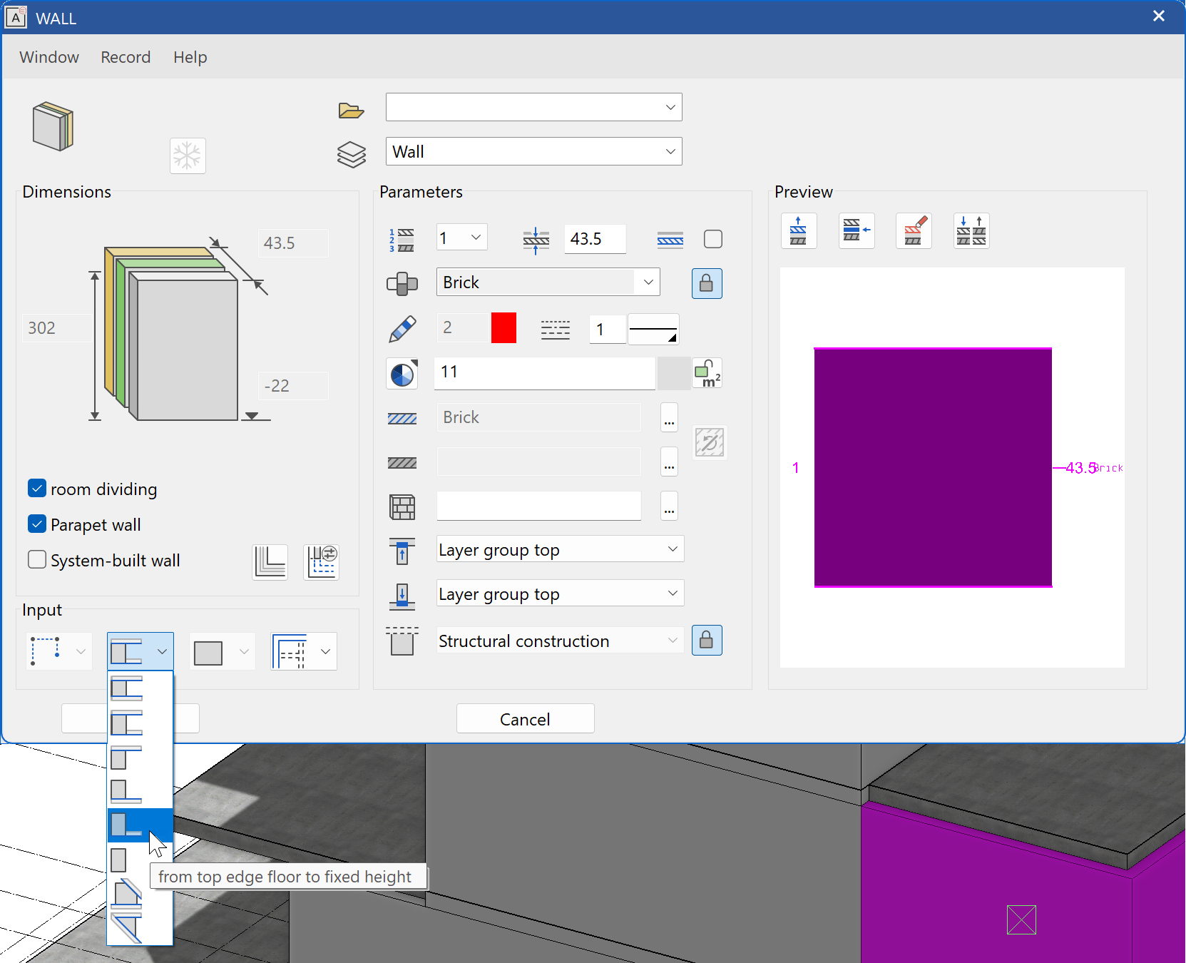
The properties of an object can be adjusted by either double clicking on it or by activating it and opening the parameters dialog from the property bar. Select the new wall in the NF1 and open the parameters dialog.
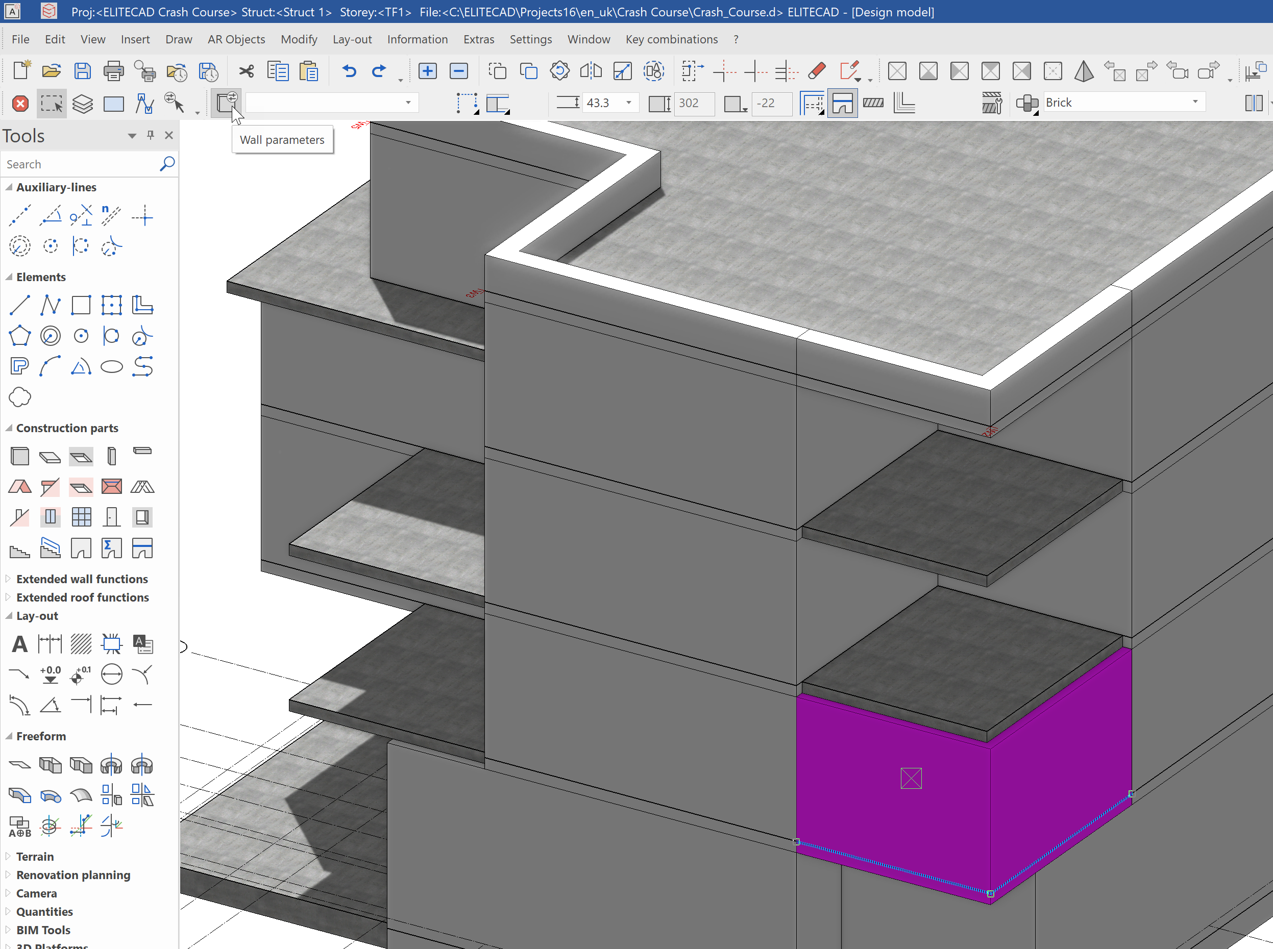
Our wall is set so that it will automatically use the storey height. To make it a parapet wall, we must change the height reference of the wall on the first floor to from top edge floor to fixed height.
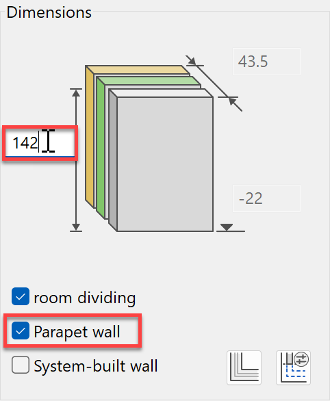
After that, we set the height to 142 cm and define the wall as a parapet wall.
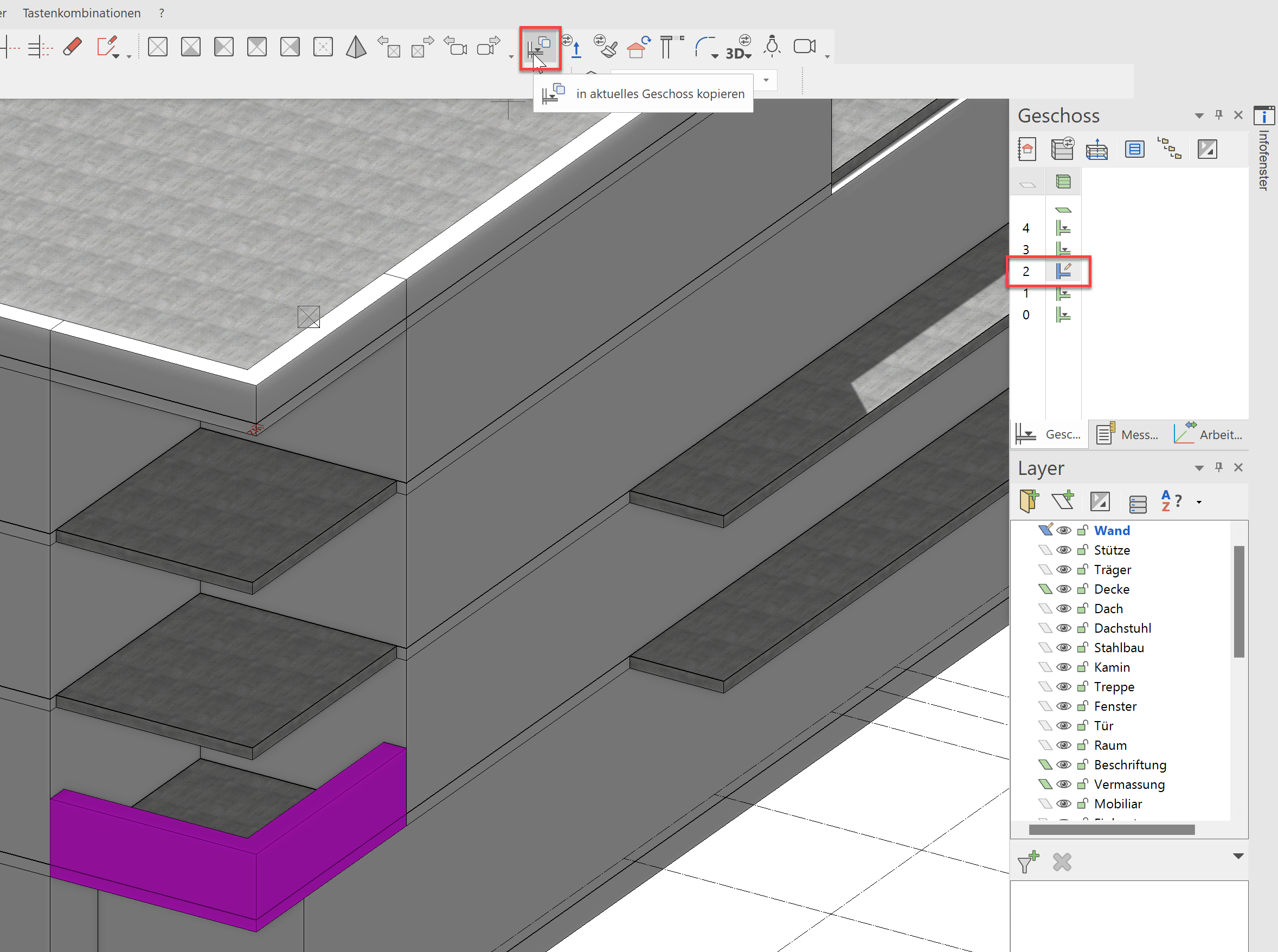
By doing this, the parapet wall is completely configured and we can copy this into the upper storeys. As we did earlier, we must first activate the desired storey, then select the construction element and start the Copy into active storey function.
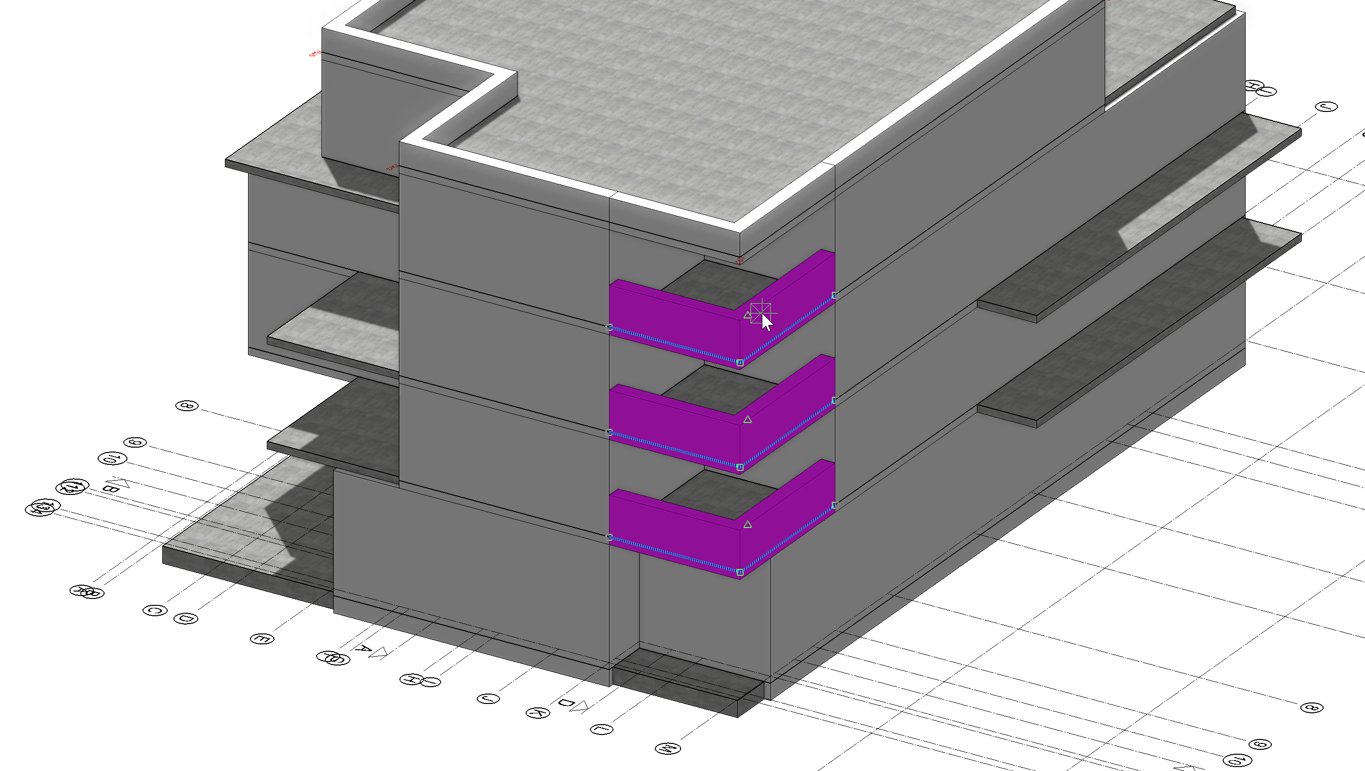
The parapet wall is needed for the first floor, second floor and top floor. For the roof, a different height is already determined.
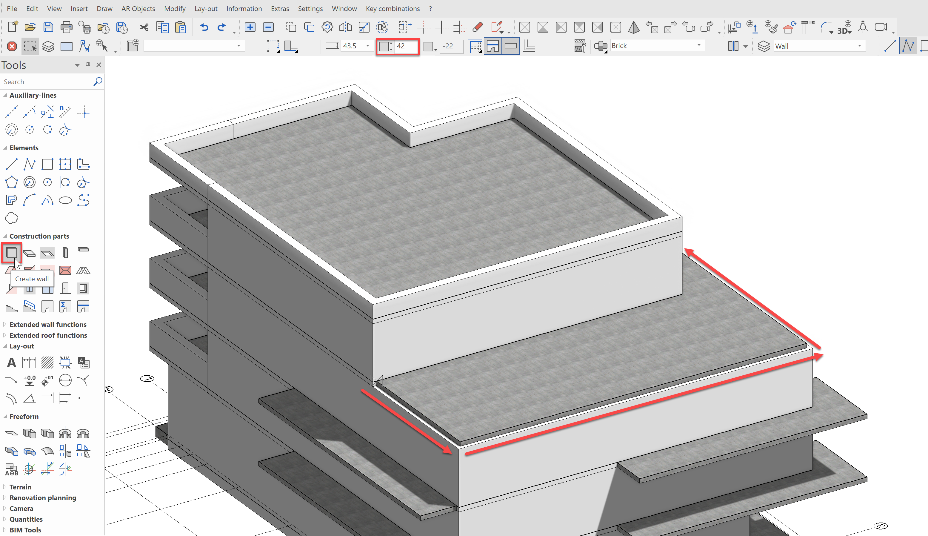
Now a parapet wall is needed in the top floor for the penthouse apartment, on which a railing will later be placed. To do this, we first activate the TF1, start the wall function and enter the height as 42 cm. Follow the contour of the balcony slab up to the corresponding wall connection.
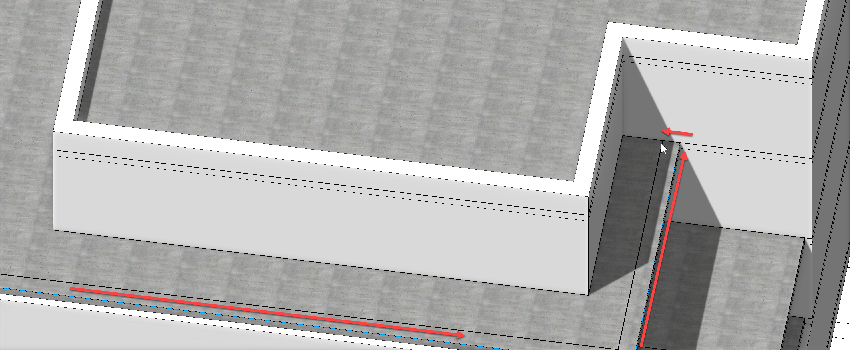
The contour connects to the outer wall and is finished with a double click. We must then indicate whether the wall axis should be left, right or centre. Move the mouse to the left (i.e. towards the terrace) so that the wall axis is on the right (outside). The contour of the wall is displayed as a graphical preview. With another click, the wall will be generated.
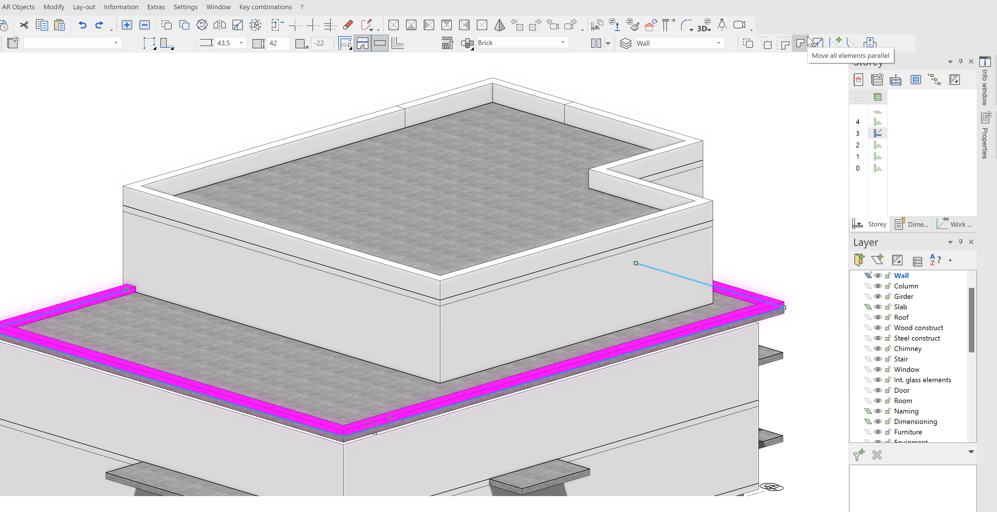
Since we followed the contour of the slab, we still have to offset the wall outwards by the thickness of the insulation (18.5 cm).
This is done by selecting the wall followed by the Move all elements parallel function in the input assistant.
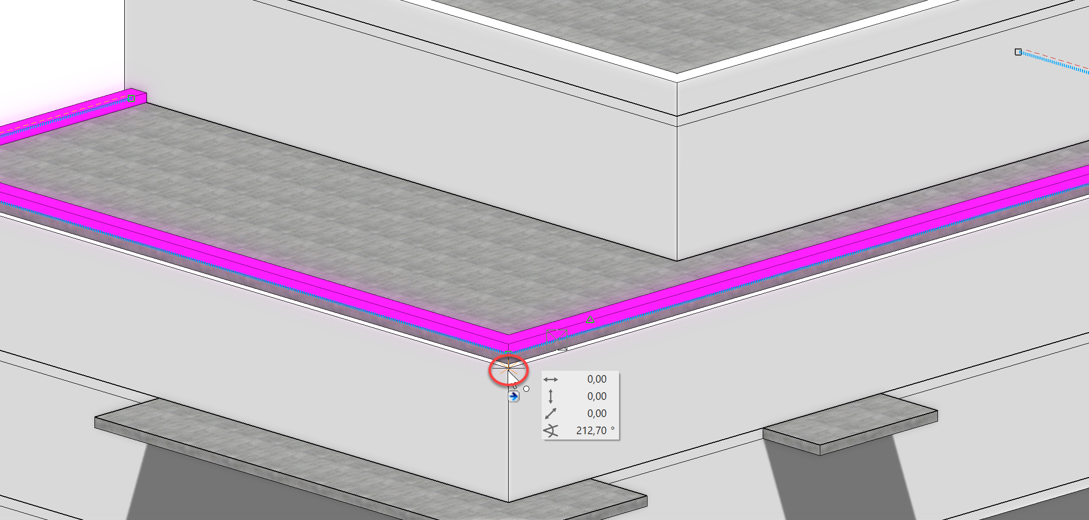
Now all you have to do is capture the corner point of the wall from the storey below and the wall will be pulled out accordingly.
Alternatively, we could have traced the contour of the underlying wall when first creating the wall, then no later displacement would have been necessary.
The shell construction of our model is now almost finished.
Columns
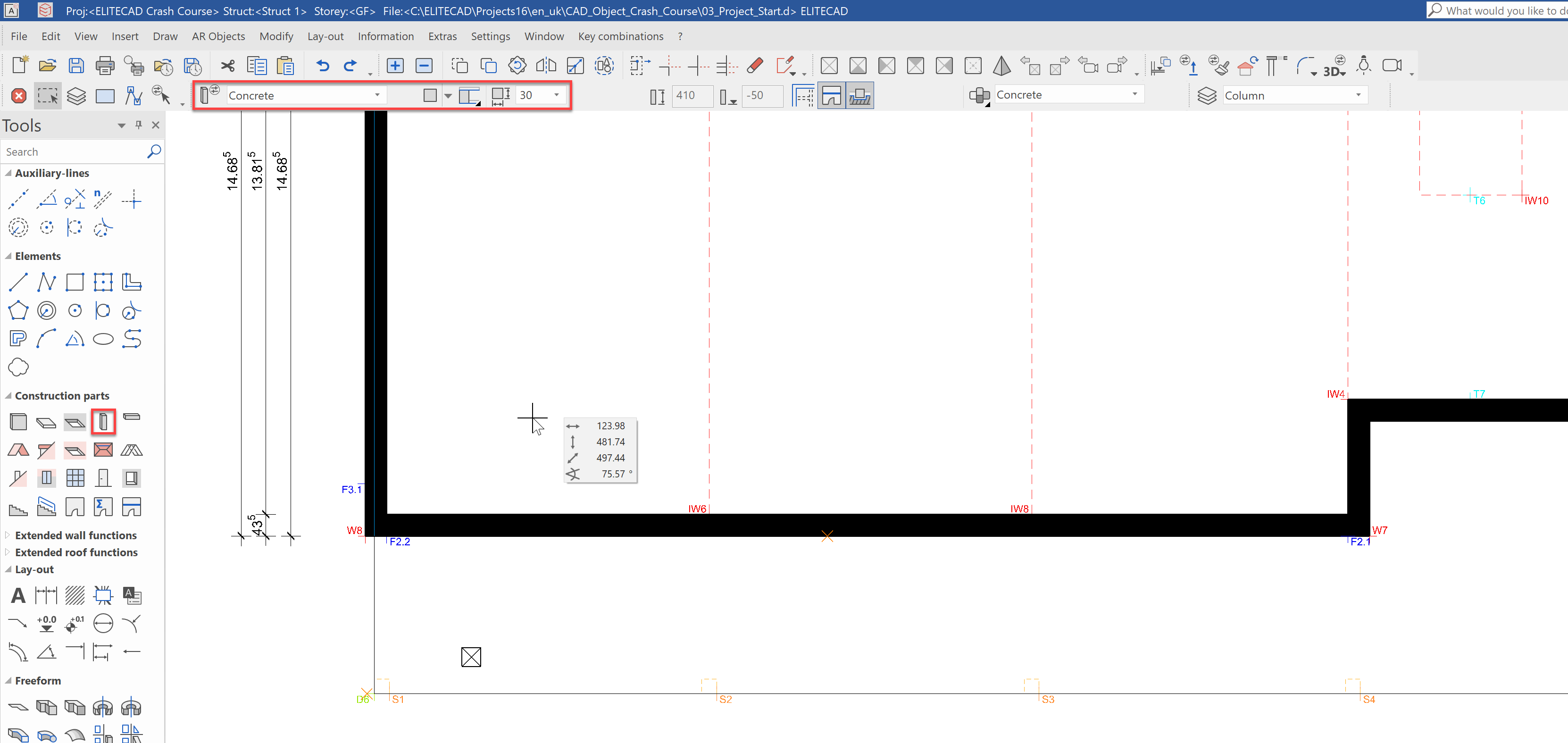
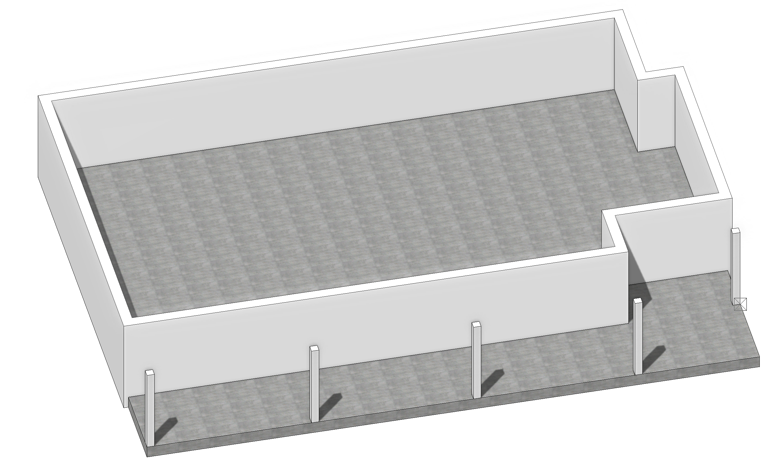
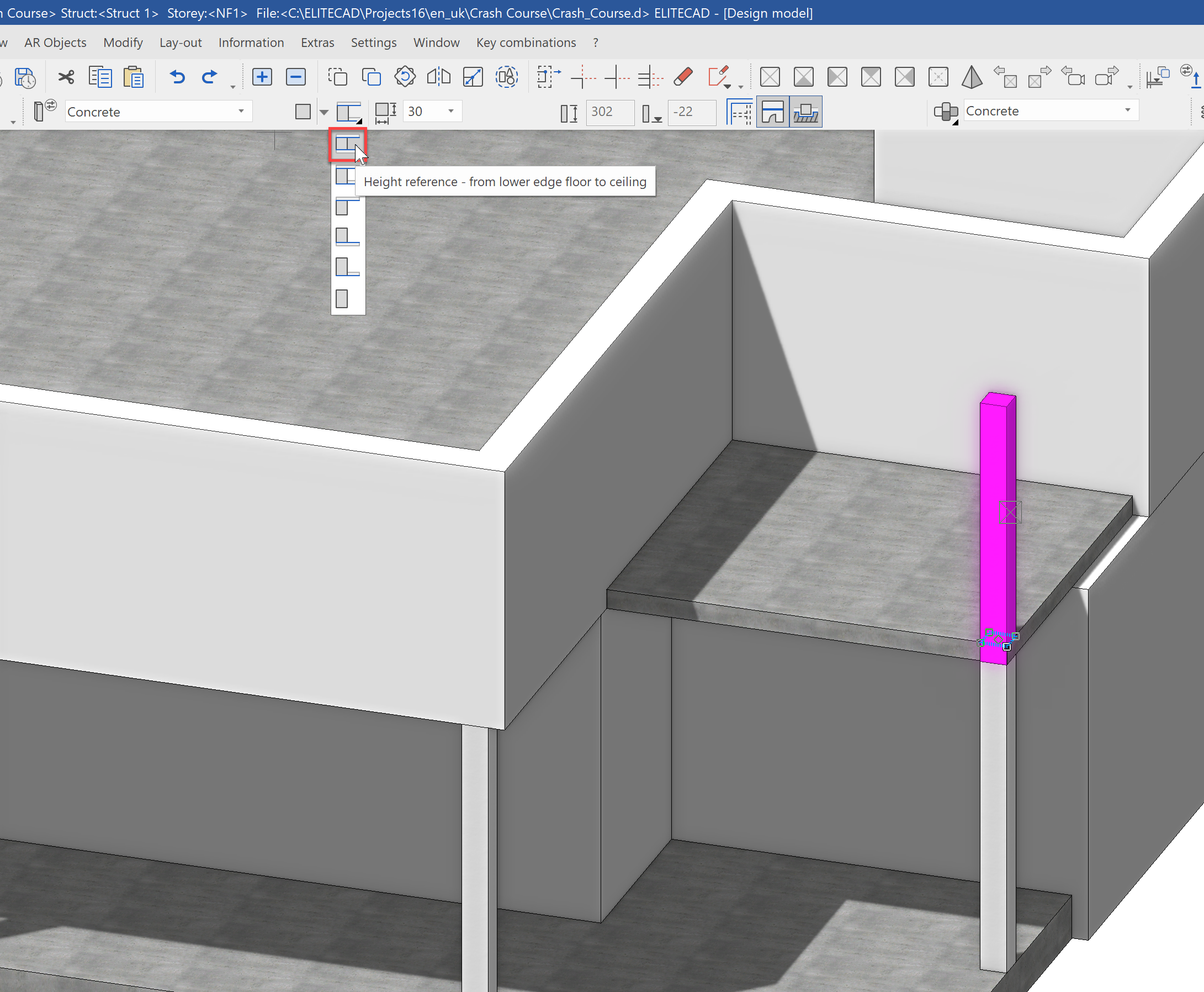
In order to support the slab of the first floor, a few support columns should be placed. This, as well, can be done in either 2D or 3D as you prefer. Next, we will show the GF alone and make the corresponding auxiliary geometry visible using the layer manager. Select the construction part column and check the settings in the property bar. We would like a concrete column with a thickness of 30 cm and a height reference setting of From lower edge floor to ceiling.
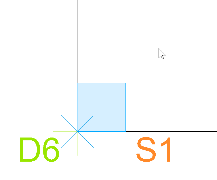
Place the first column on the Point S1.
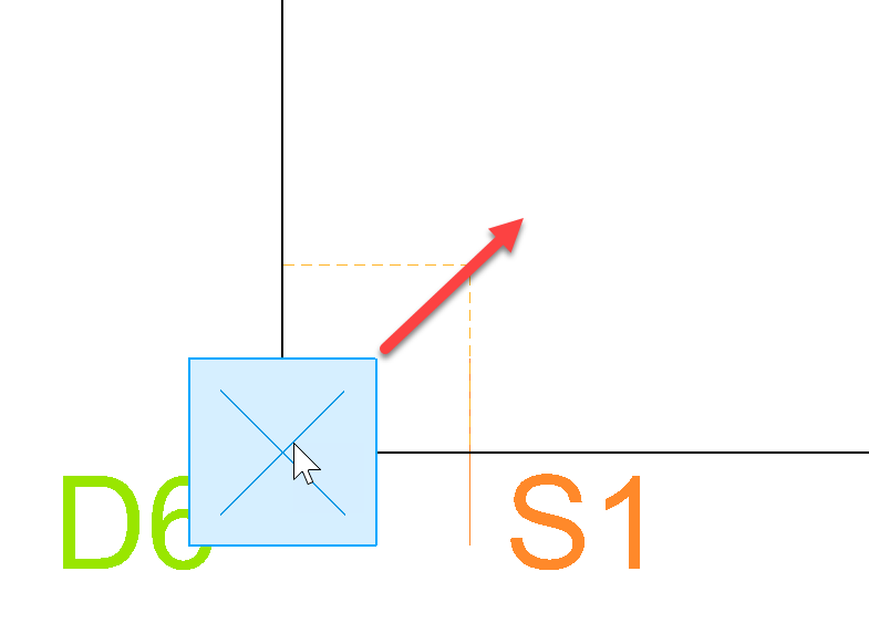
With a second click, you enter the direction - for this case, inward.
Place the columns for Points S2 - S5 in the same manner.
The column from S5 will also be copied into the NF1
But here we notice a problem immediately - the height reference is not correct. The columns in the GF were from lower edge floor to ceiling, but in the first floor, we need to correct this to from floor to ceiling.
Our complete construction shell now looks like this: