Windows and doors
Next, our building model will need some windows and doors. Here, too, there are numerous variants and setting options in ELITECAD. For this course, we have already predefined the required data records, so that you only have to place them into the model and possibly adjust them slightly.
Ground floor doors
We will start with the interior doors in the GF. Next we will show the GF alone and switch to the 3D solid mode. The layer Aux. Geometry GF should be visible. If you do not see the auxiliary points in solid mode, you may first have to make the elements visible using Ctrl+E.
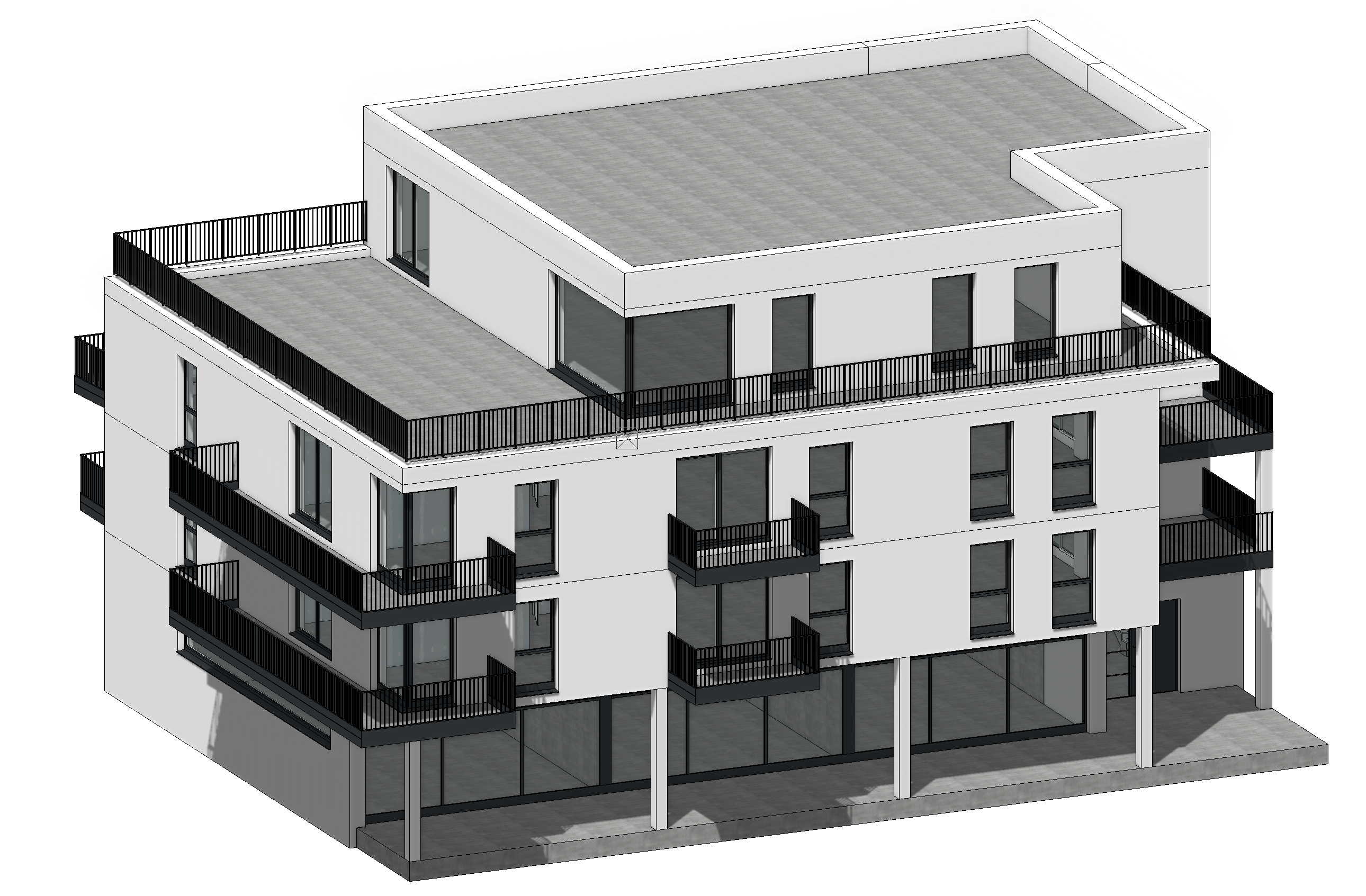
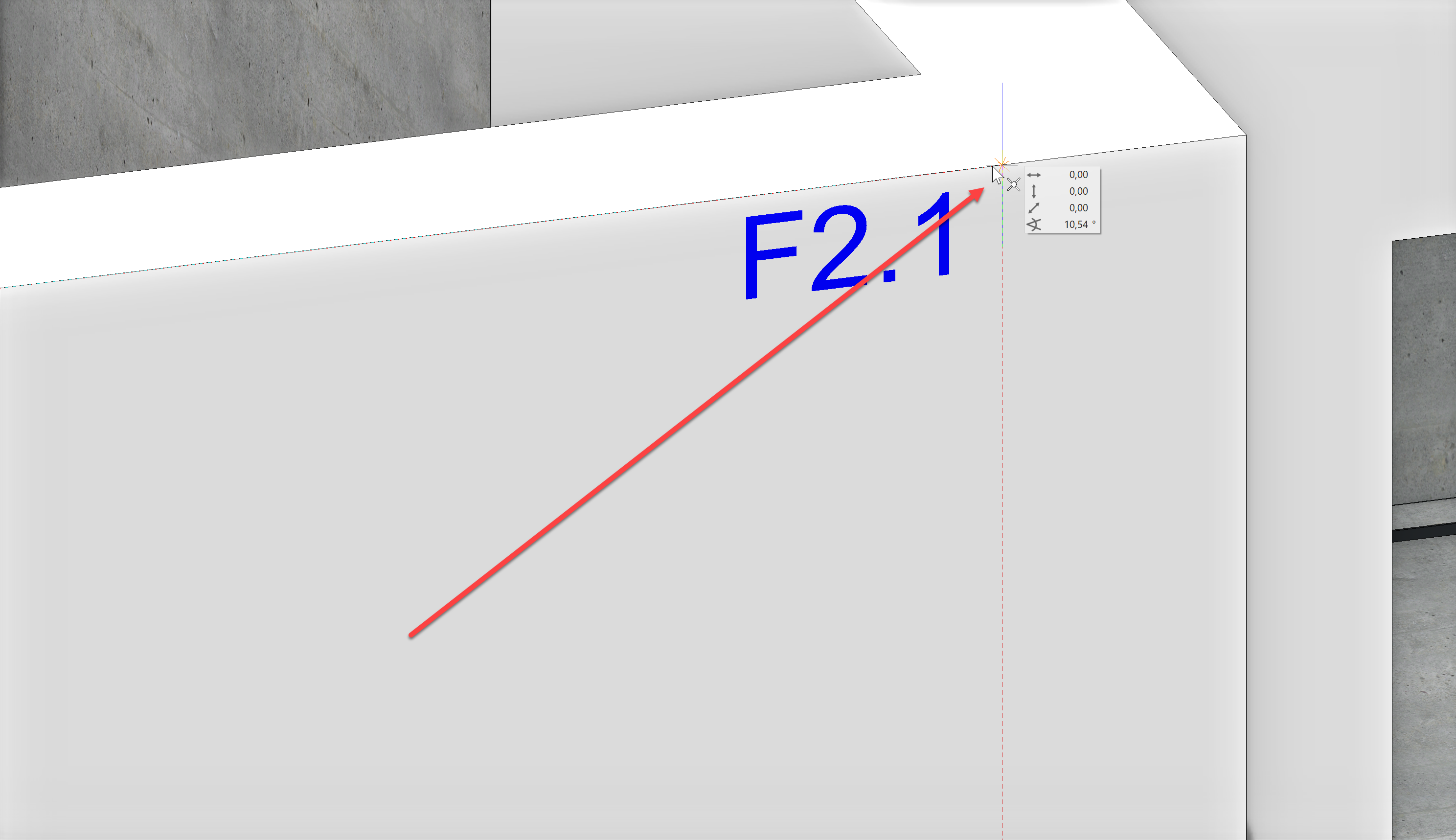
To set the first interior door, select the construction part Create door from the tools manager Construction parts. We will use the data record Standard and a reveal width of 90 cm.
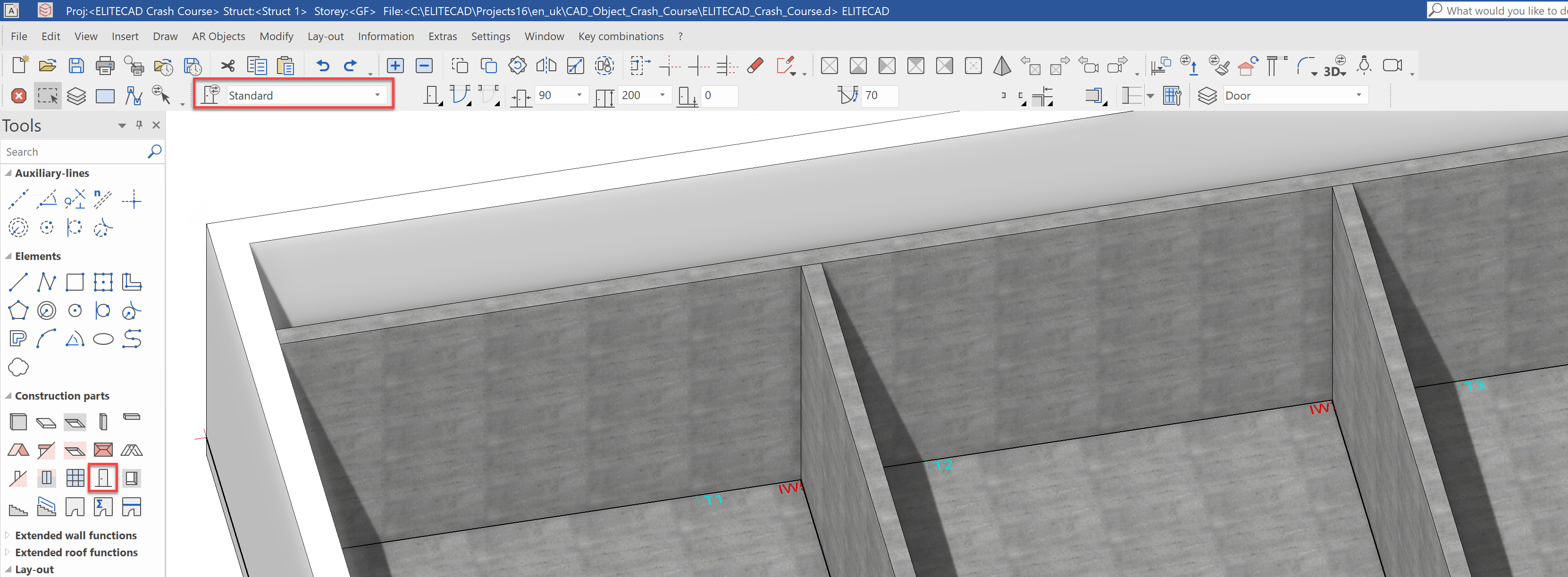
Set the first door with a click on Point T1. Now, you can use the mouse to chose the position of the stop. In our case, the door should sit in the centre and open into the room.
When you have reached the desired position, click a second time to set the door.
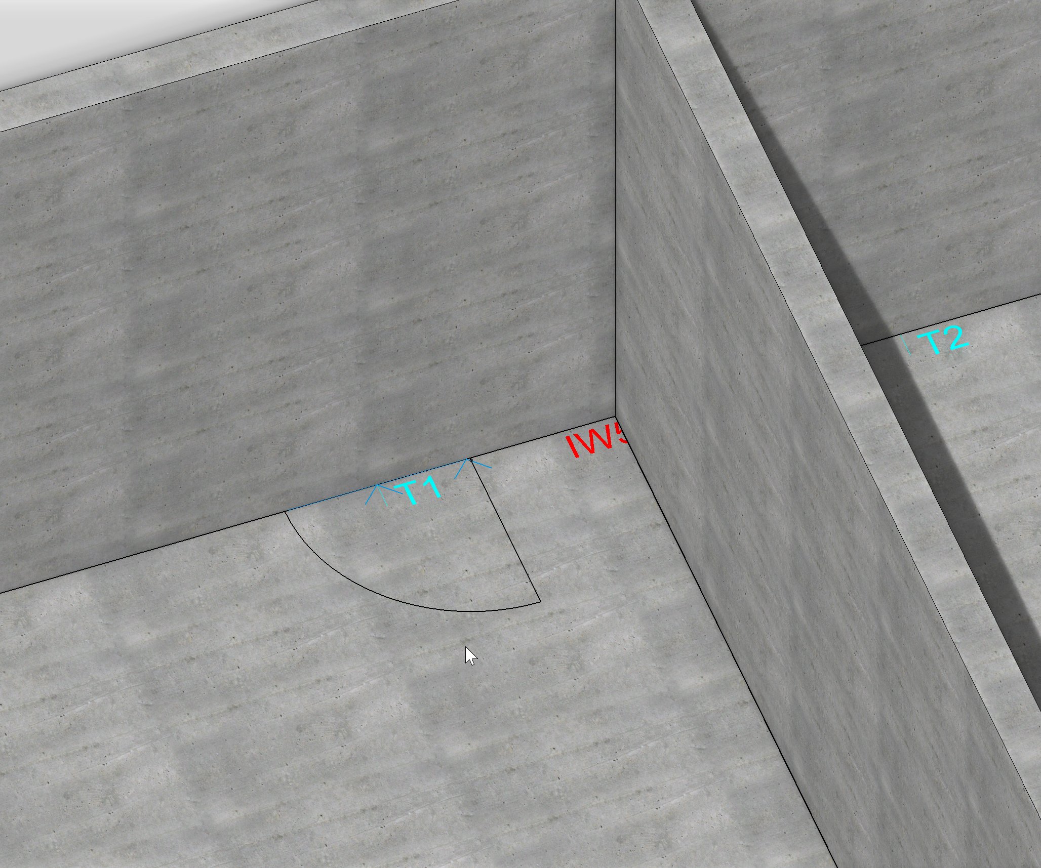
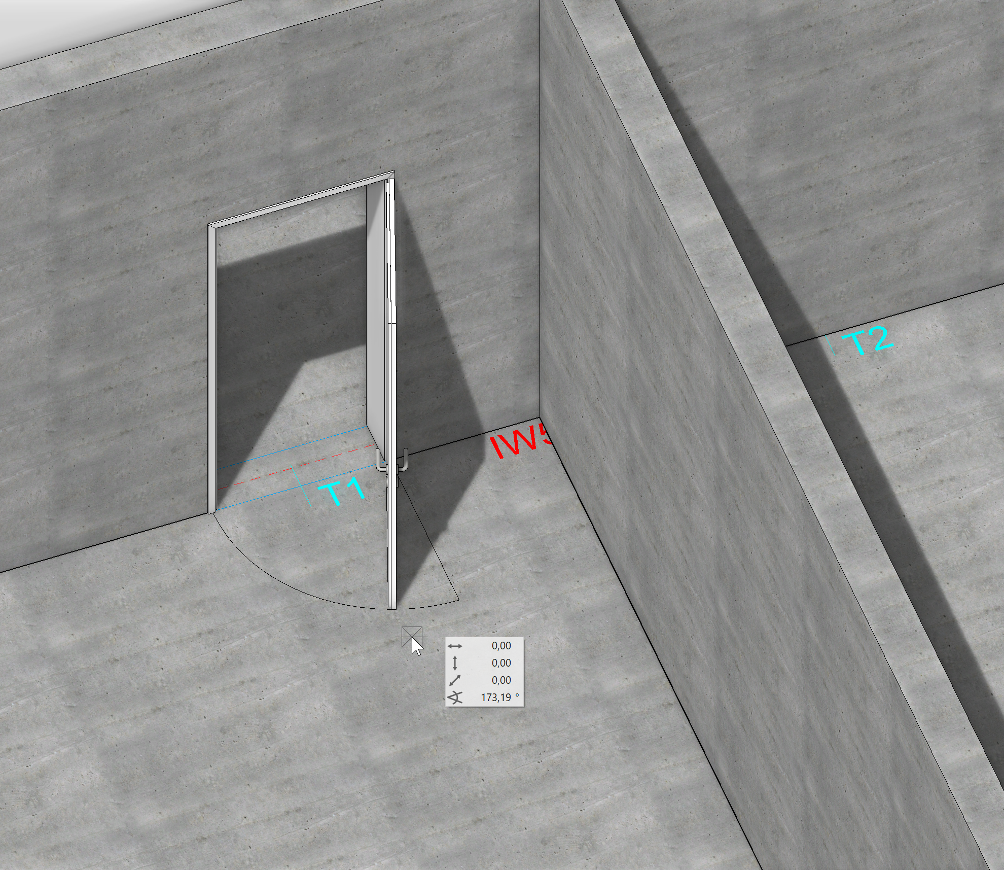
The result should look like this:
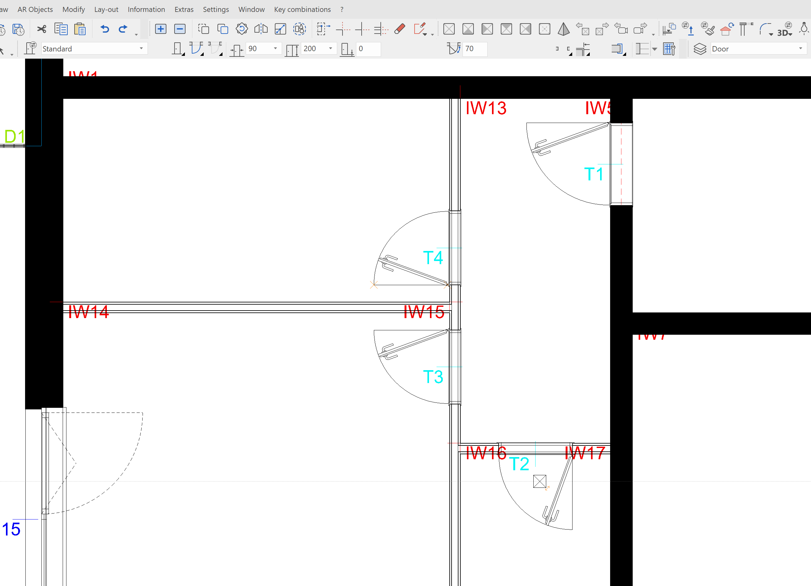
Also place the doors T2, T3 and T4 using the data record Standard and the opening directions as shown:
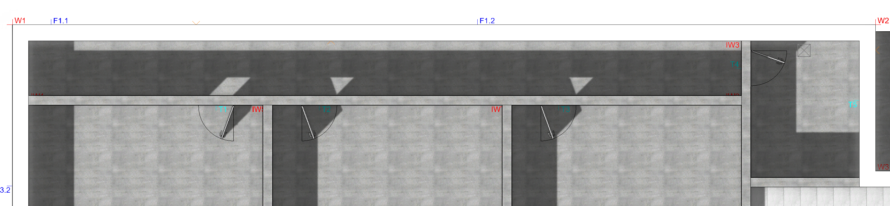
In the back entryway, a storeroom door should be placed. Select the data record CC_Storeroom_Door for this and place it at Point T5
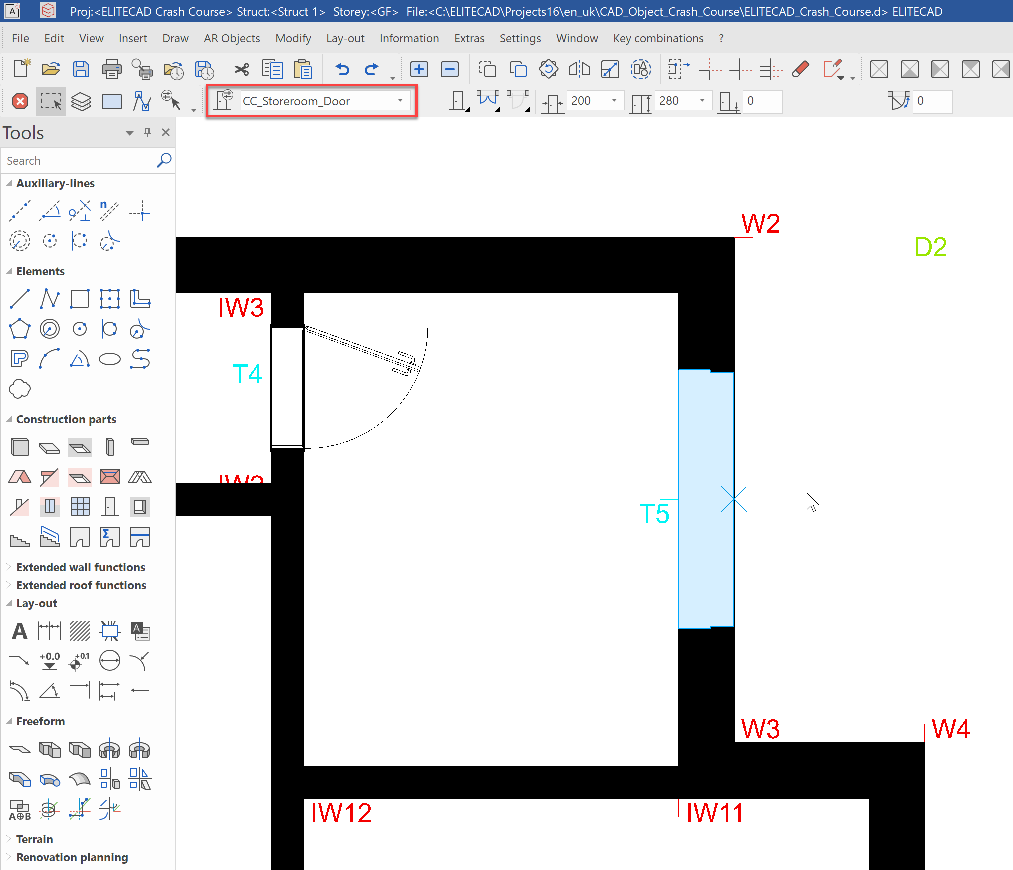
The door should open outward:
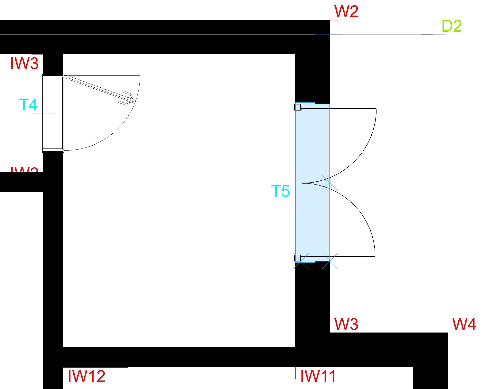
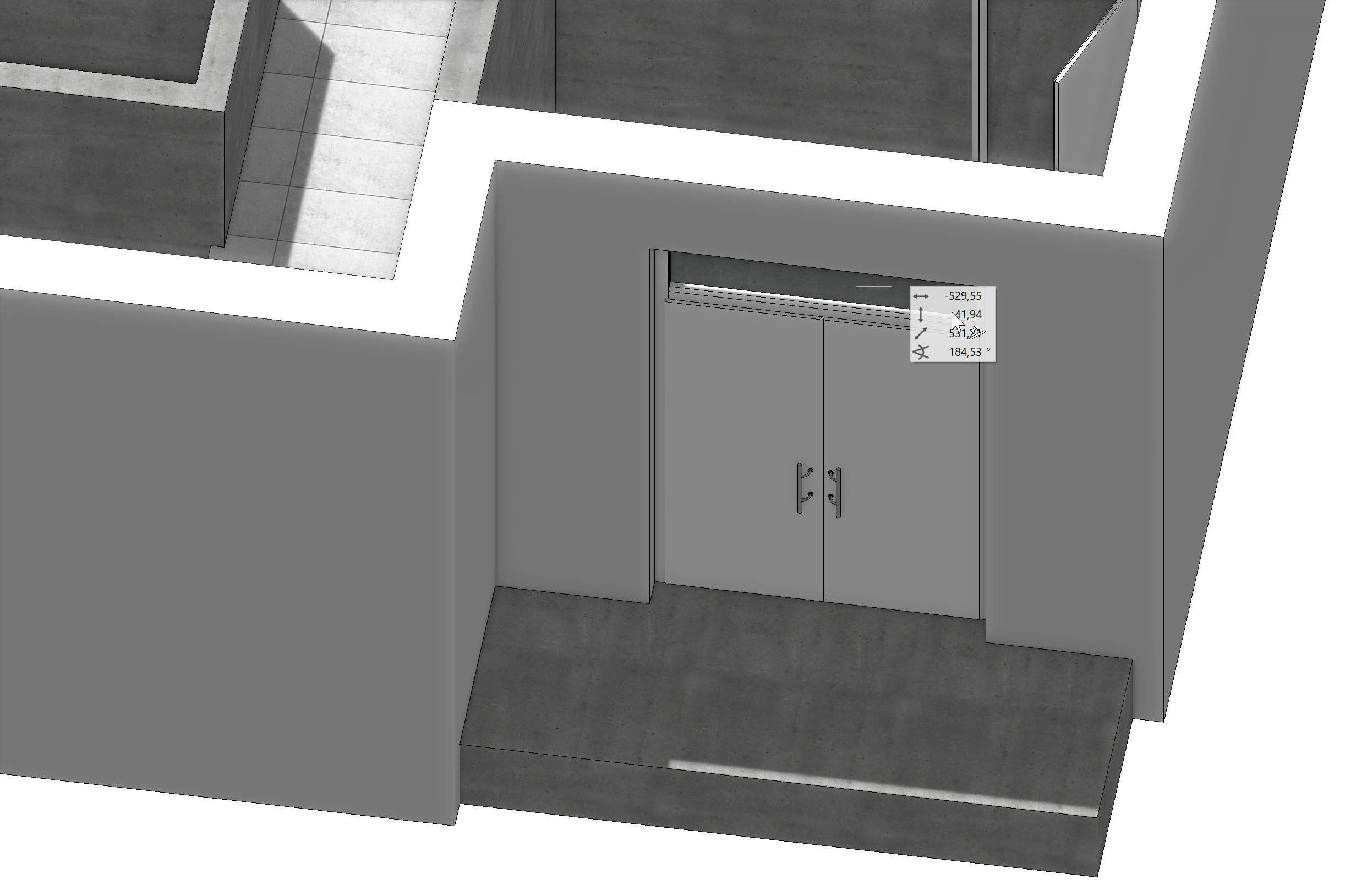
The finished doors should look like this:
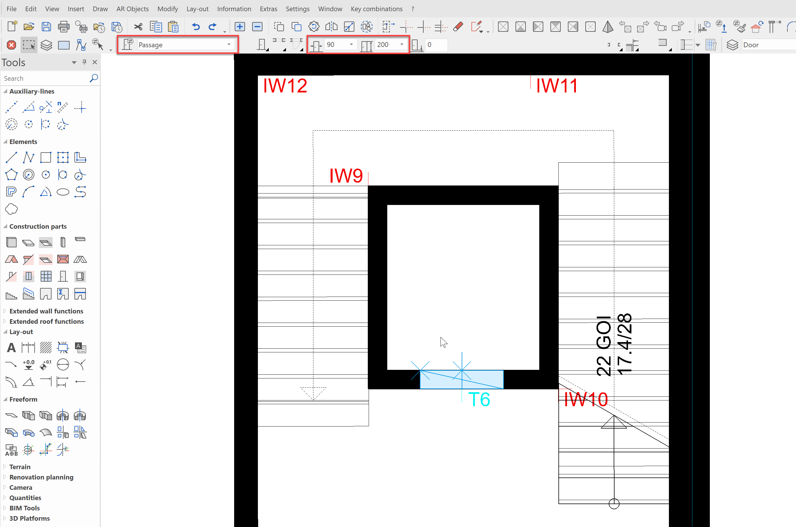
Next, we will define an opening for the elevator shaft. Select the data record Passage with a width of 90 cm and position it on Point T6.
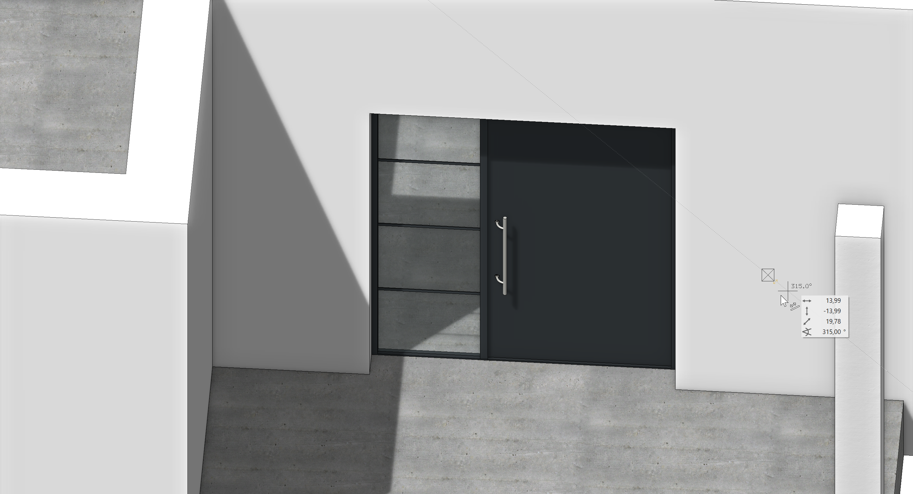
For the entrance, we want a nice-looking house door with a side-panel. Select the data record CK_Entrance_Door. Place the door at Point T7, centred and opening inwards:
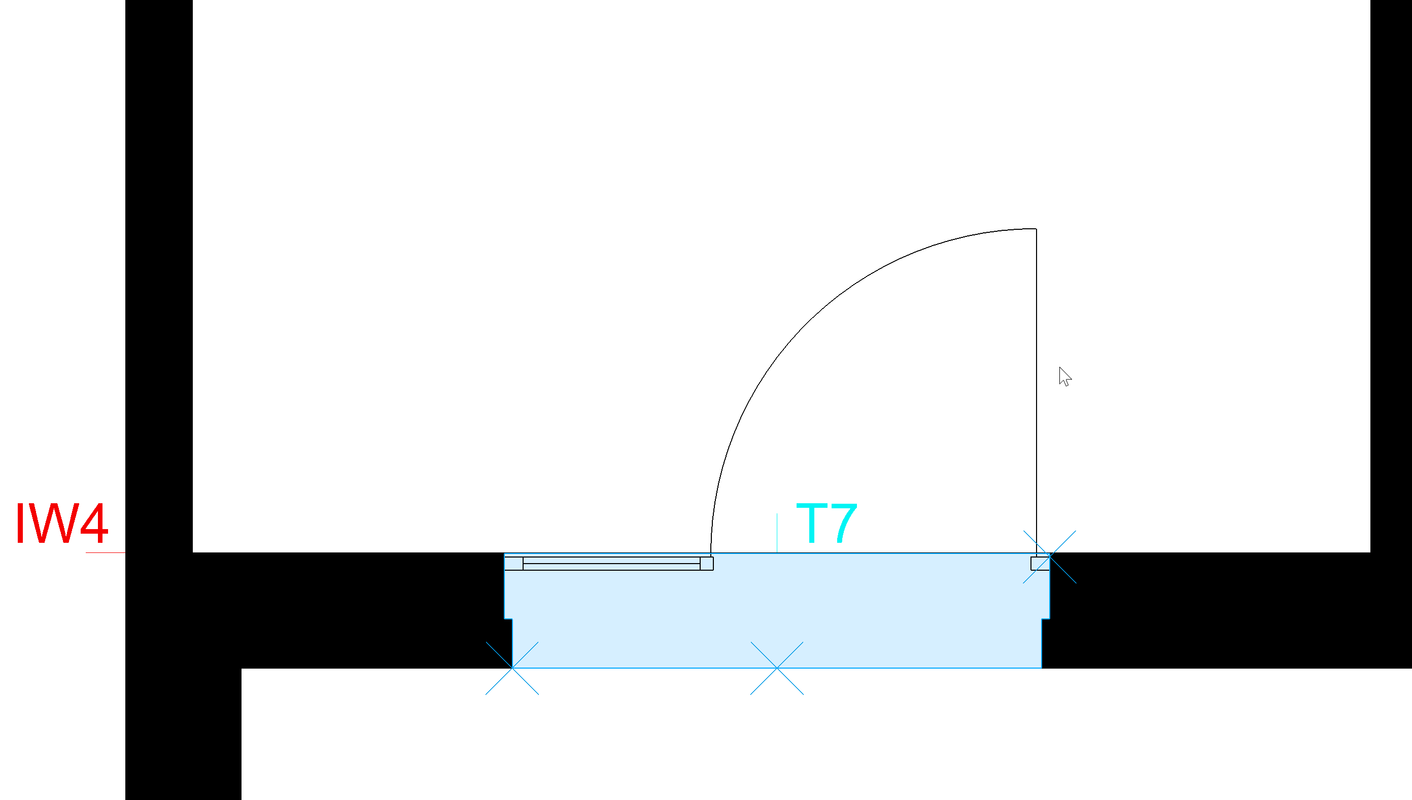
The finished door should look like this:
Ground floor windows
We now come to the windows. To begin with, we want to make a large glass element on the front side of the GF, which is to later serve as a sales floor. Windows can, in ELITECAD, be placed as predefined construction parts or dynamically adjusted in size. Since our glass element is a special size, we want to define the window using a rectangle.
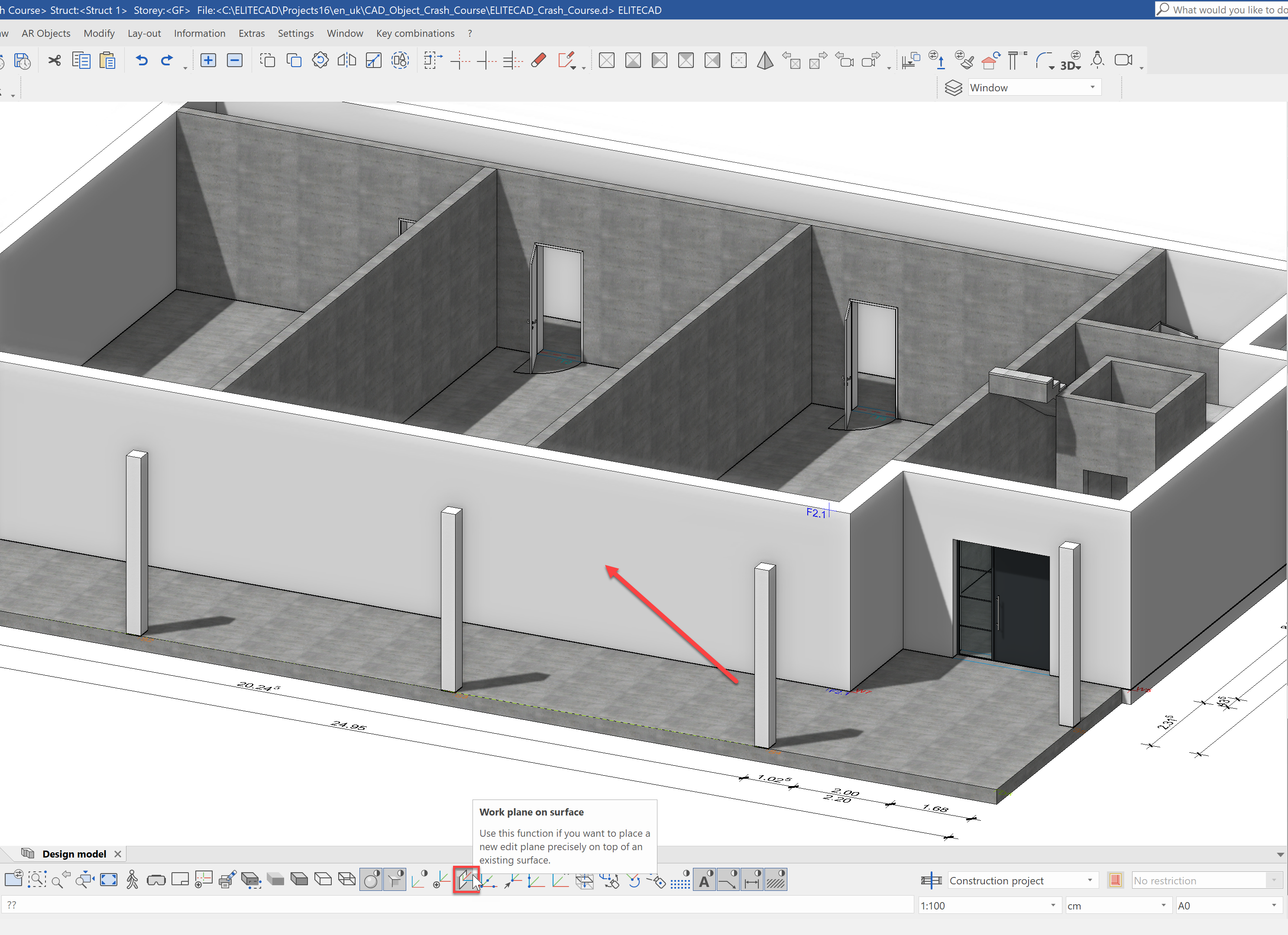
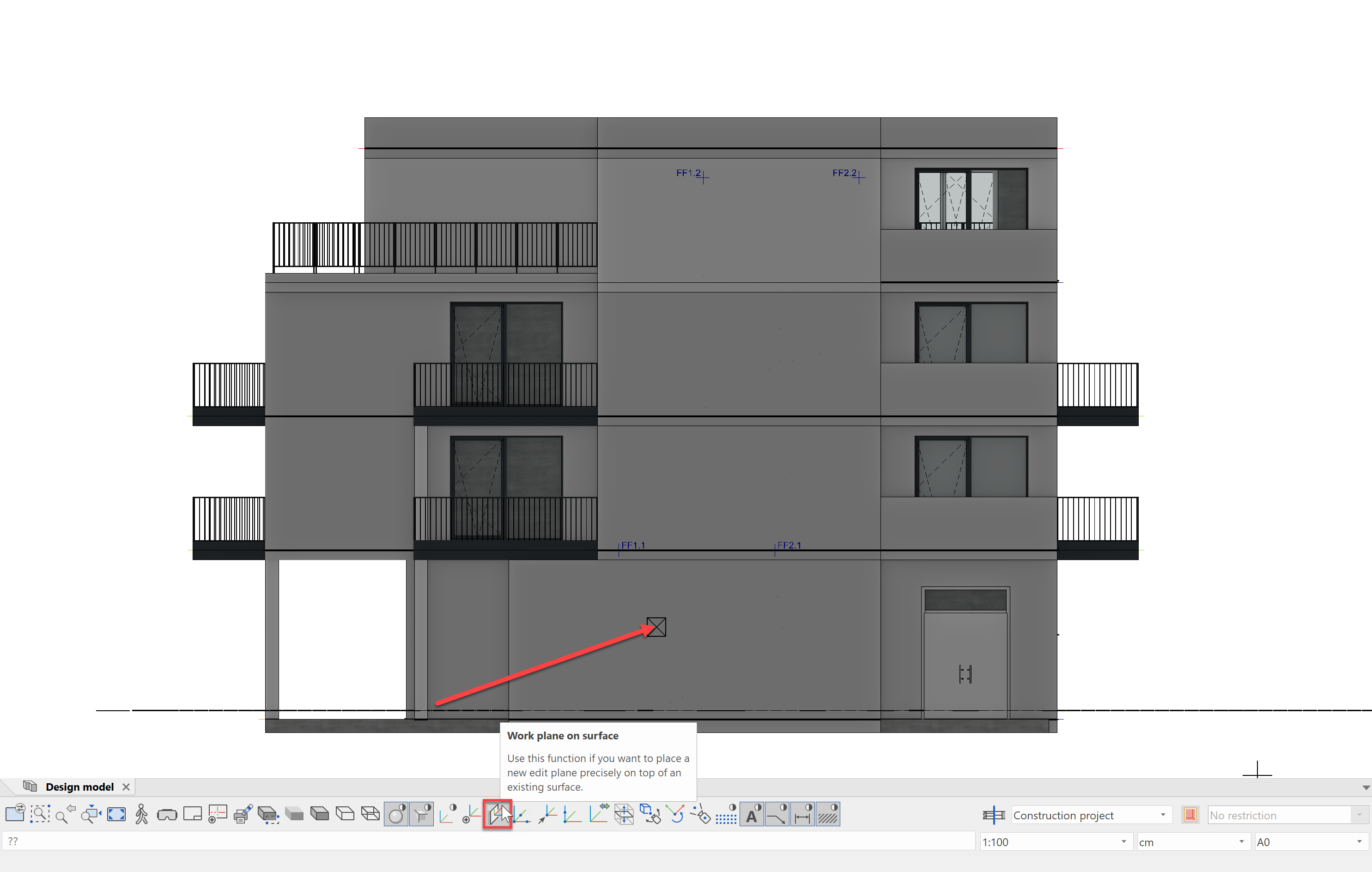
For the 2D drawing in ELITECAD, the work planes are used. By activating a storey, the working plane, for example is placed in the floor plan of that storey. As a result, the drawn 2D contours of walls and slabs are automatically at the correct height. Since we now want to create a window on the facade, we need to lay the work plan on the facade surface.
To accomplish this, we will use the function Work plane on surface from the image properties. Then click on the facade, to select the surface.
Now when you use the shortcut Ctrl+D, the view will not turn to the top view as normal, but rather to the facade. If we now draw 2D elements, they are on the facade surface, even if we are in the 3D representation.
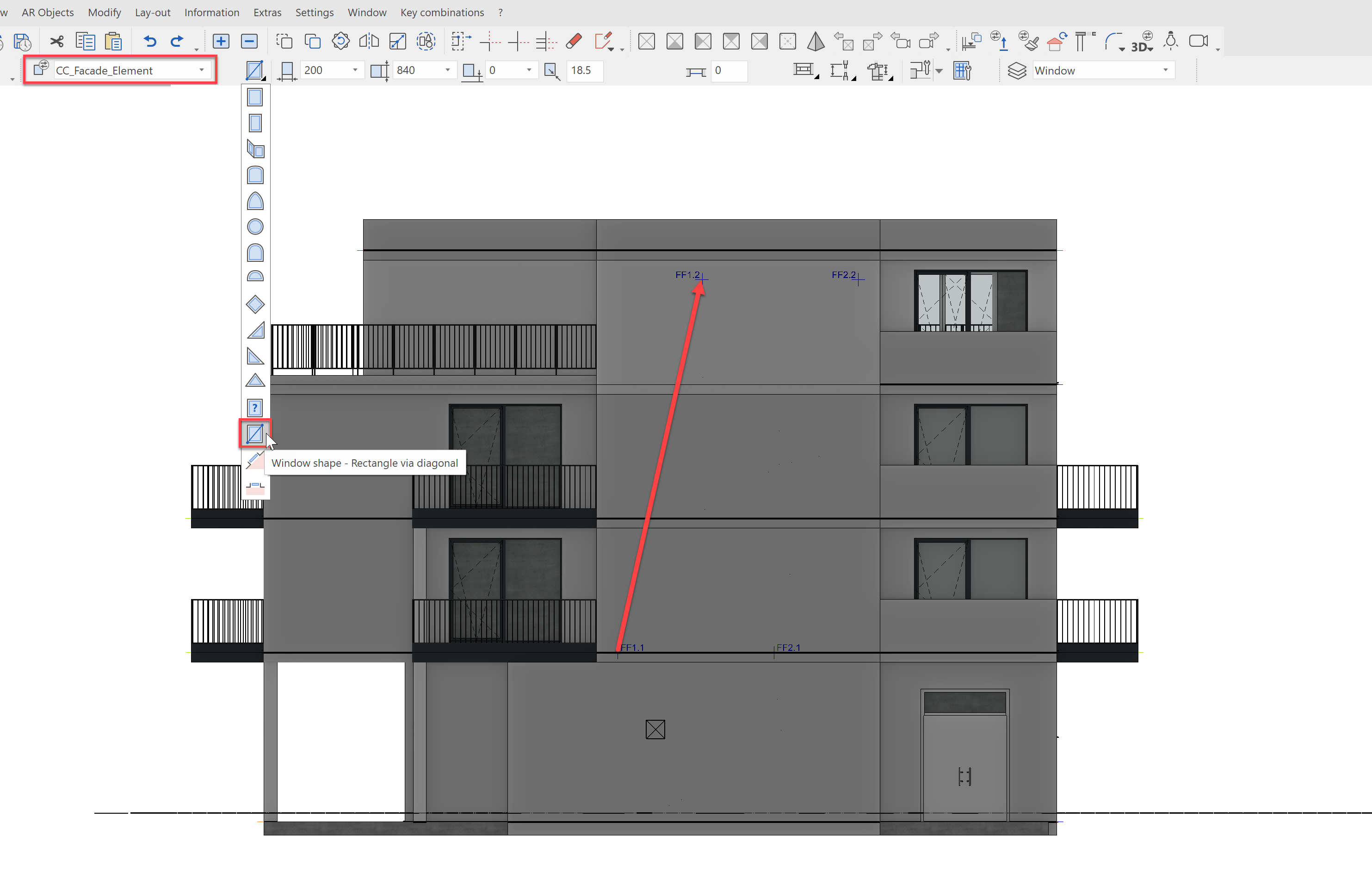
Let's draw the window with a rectangle. Select the construction part Create window from the tools manager Construction parts and select the data record CC_Glass_Element. From the window shape drop-down menu, select Window shape - Rectangle via diagonal.
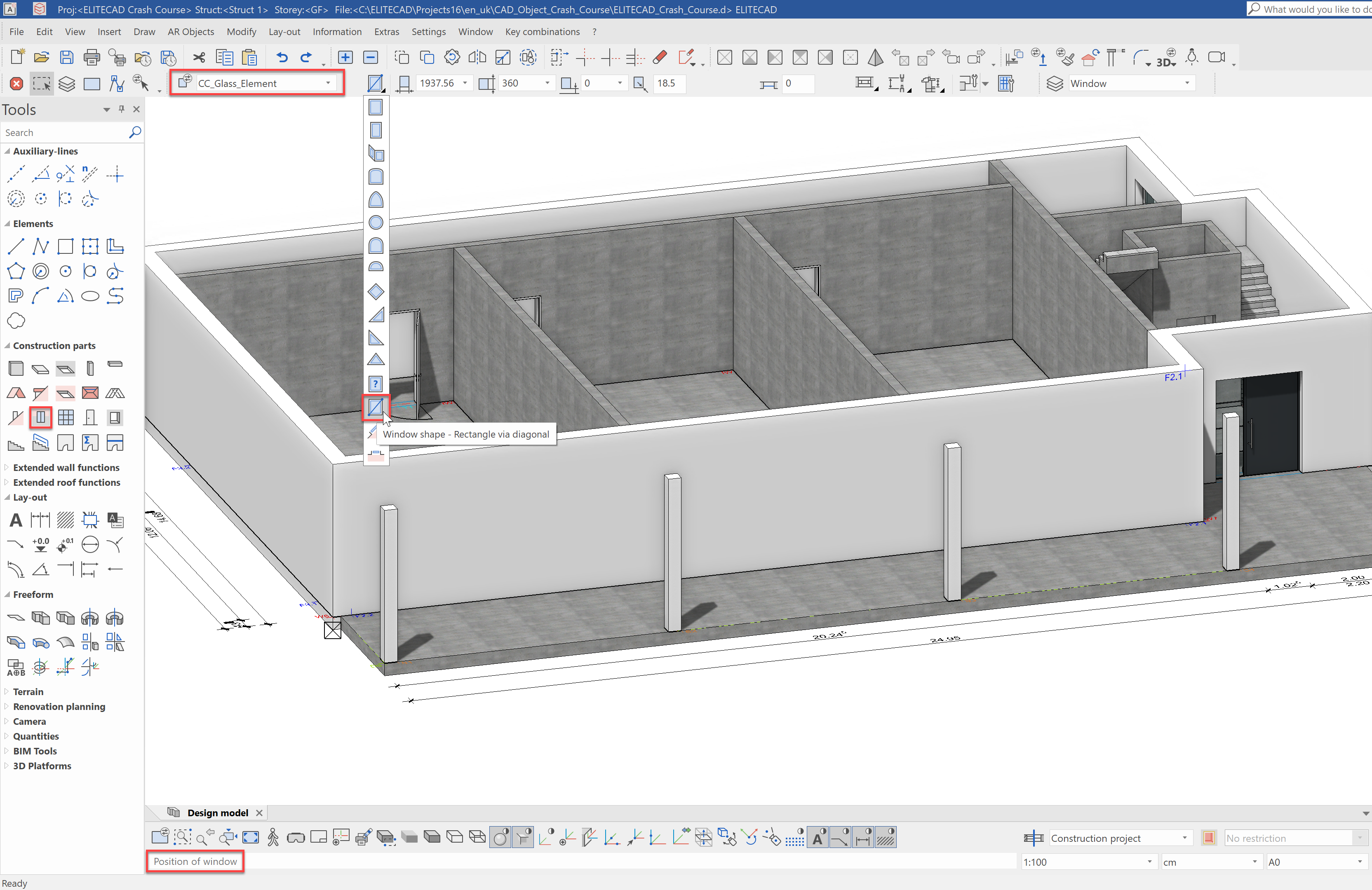
First, we must enter the lower left window point. Select Point F2.2 for this.
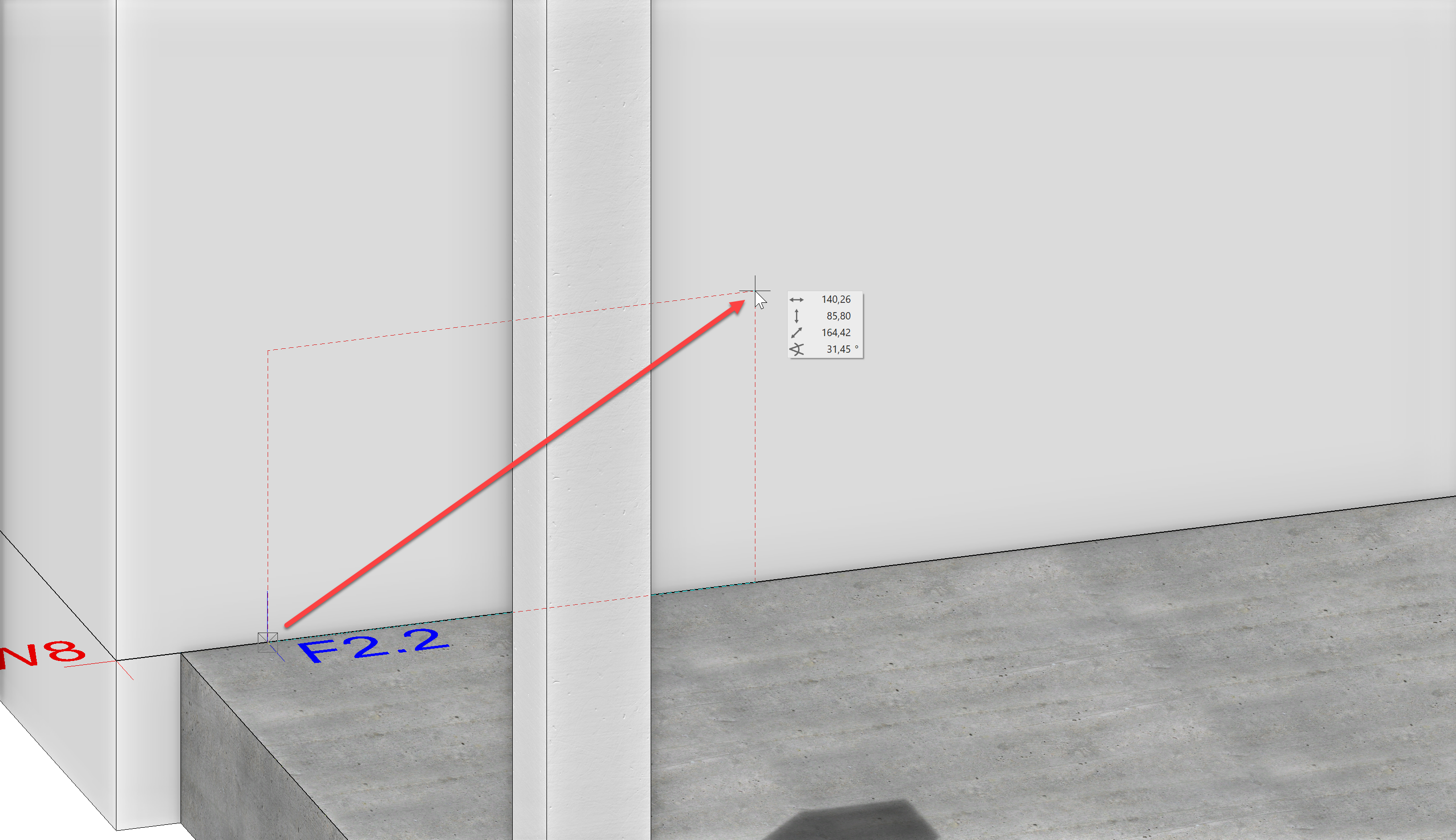
For the second point, select F2.1.
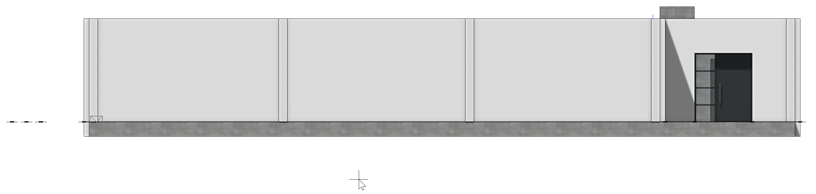
That was already it - our finished glass element should look like this:
Clicking ![]() in the image properties will reset the work plane.
in the image properties will reset the work plane.
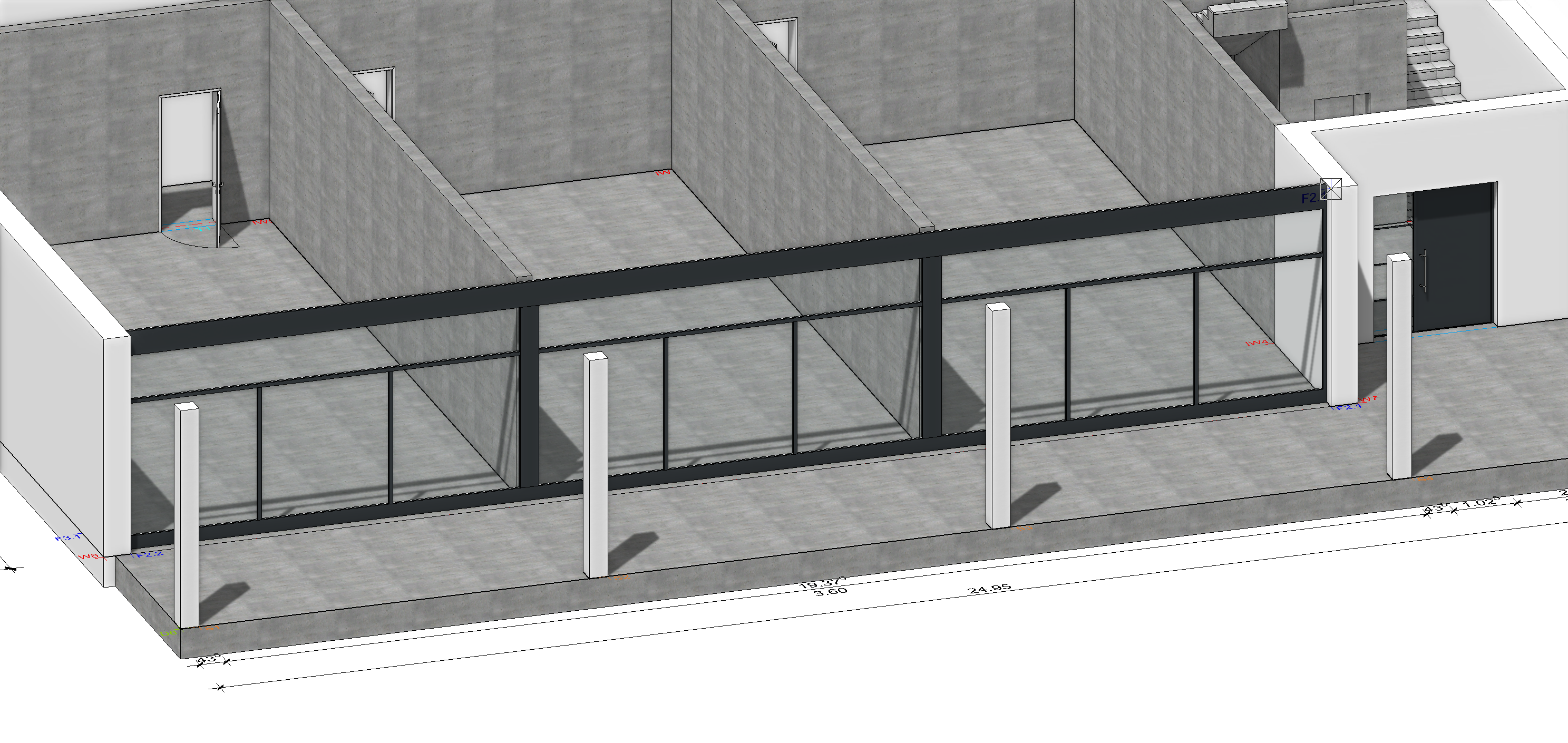
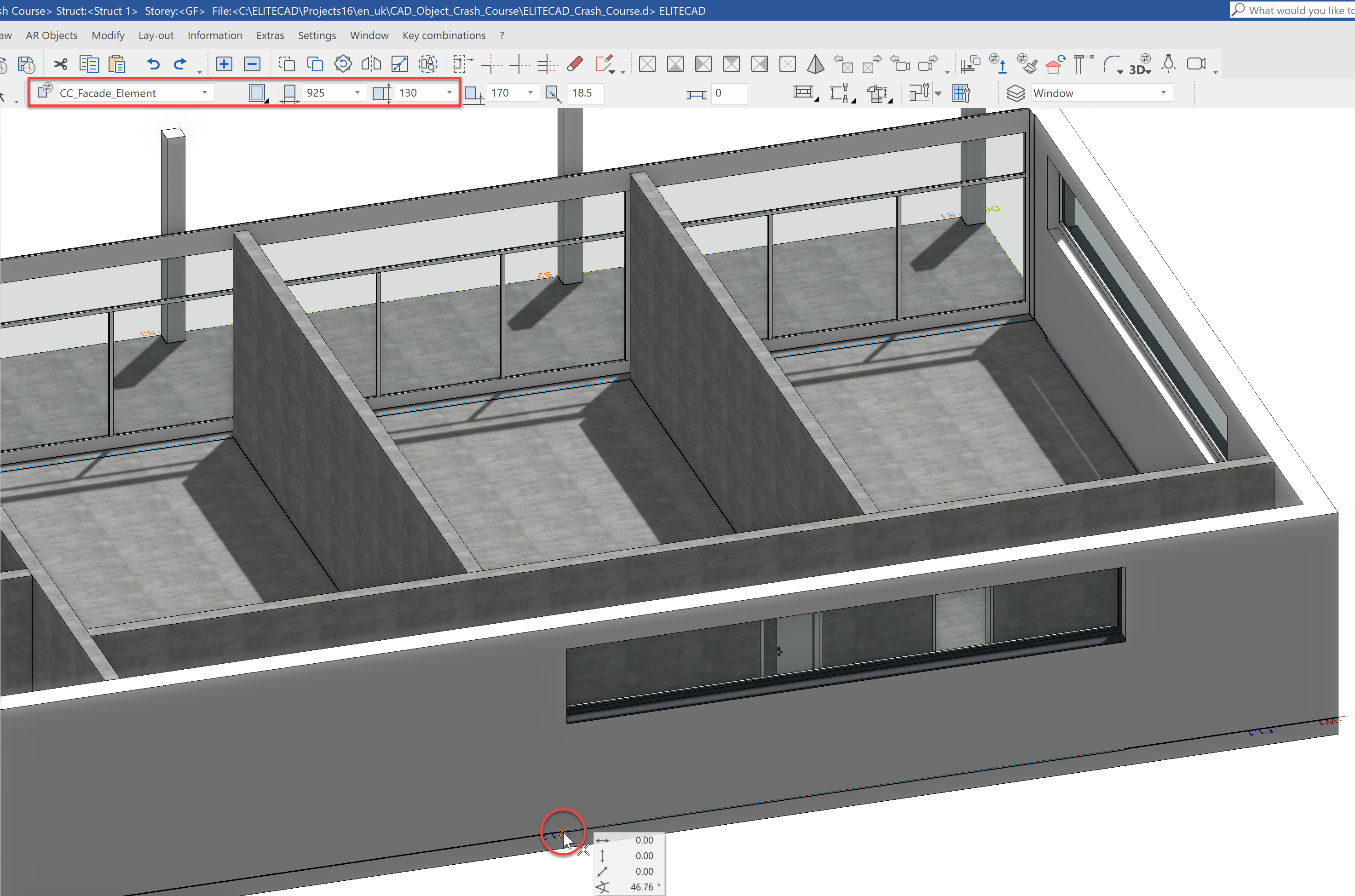
Next, we will define a side window. Select the data record CC_Fascade_Element with a width of 925 and a height of 130.
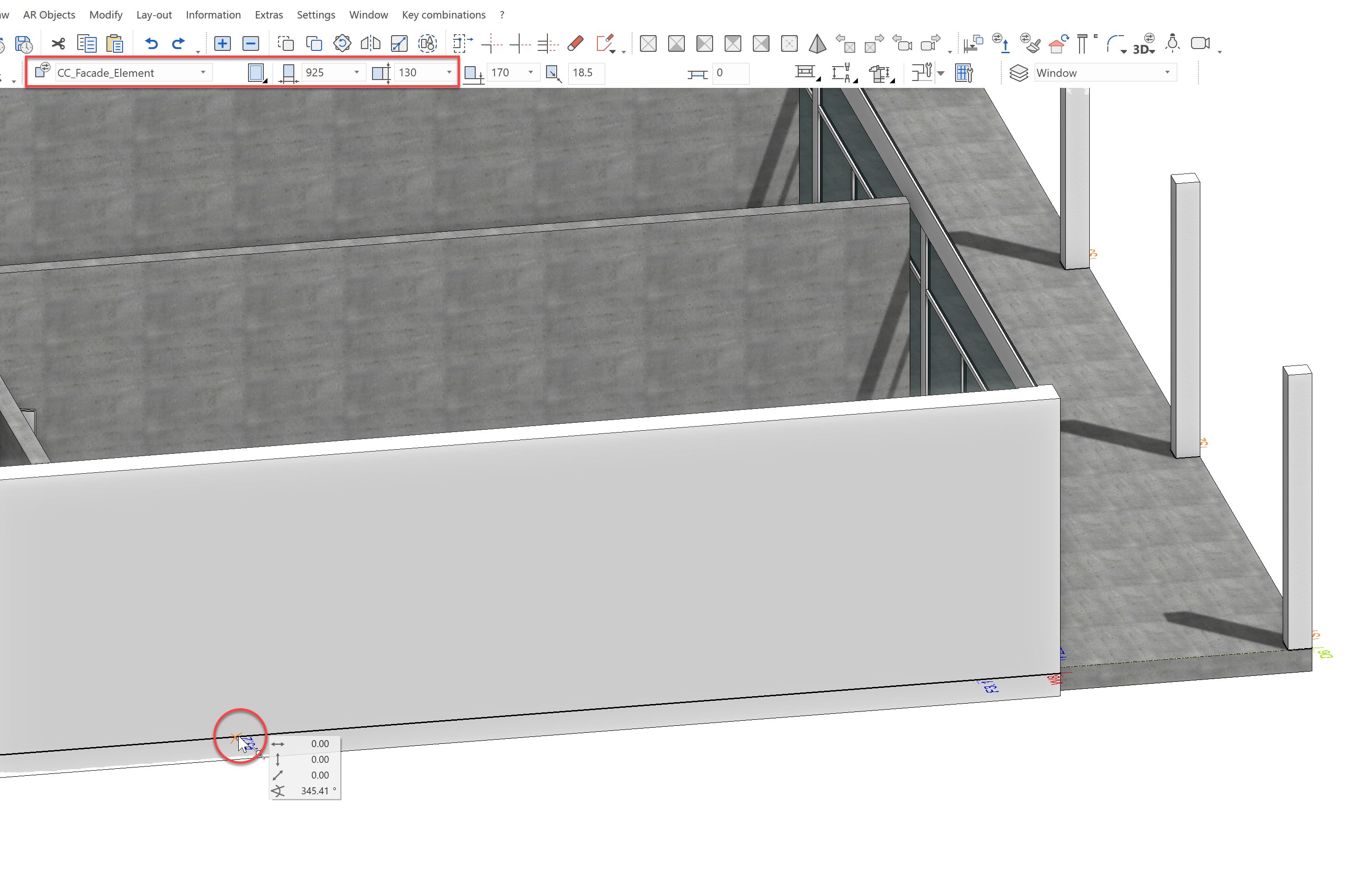
Place the window on the Point F3.2 and move the mouse to define the direction. The line shows the outside, where the label also will be.
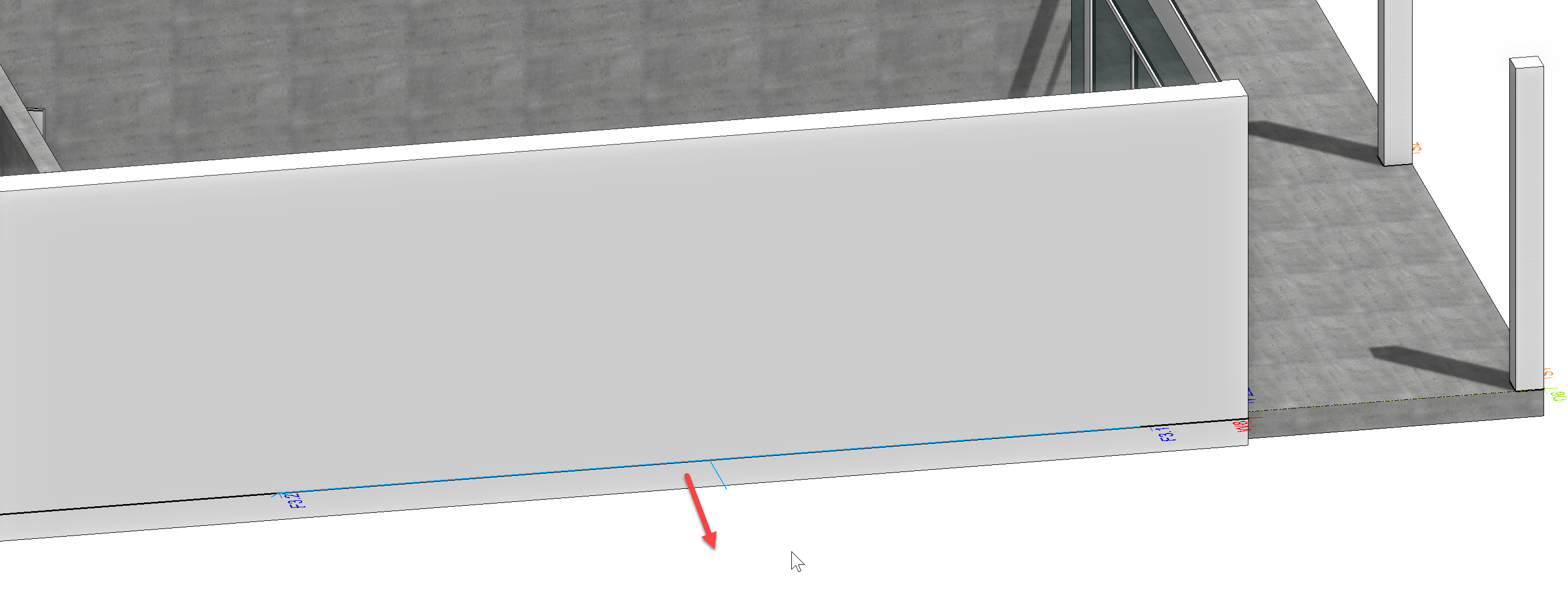
The resulting window should look like this:
Another window will also be placed on the backside. This should be somewhat larger than the side window. We could either input all settings in advance for the window or we could place it with the same dimensions as the previous window and then adjust the size.
Place the window with the same size as the one from Point F1.2.
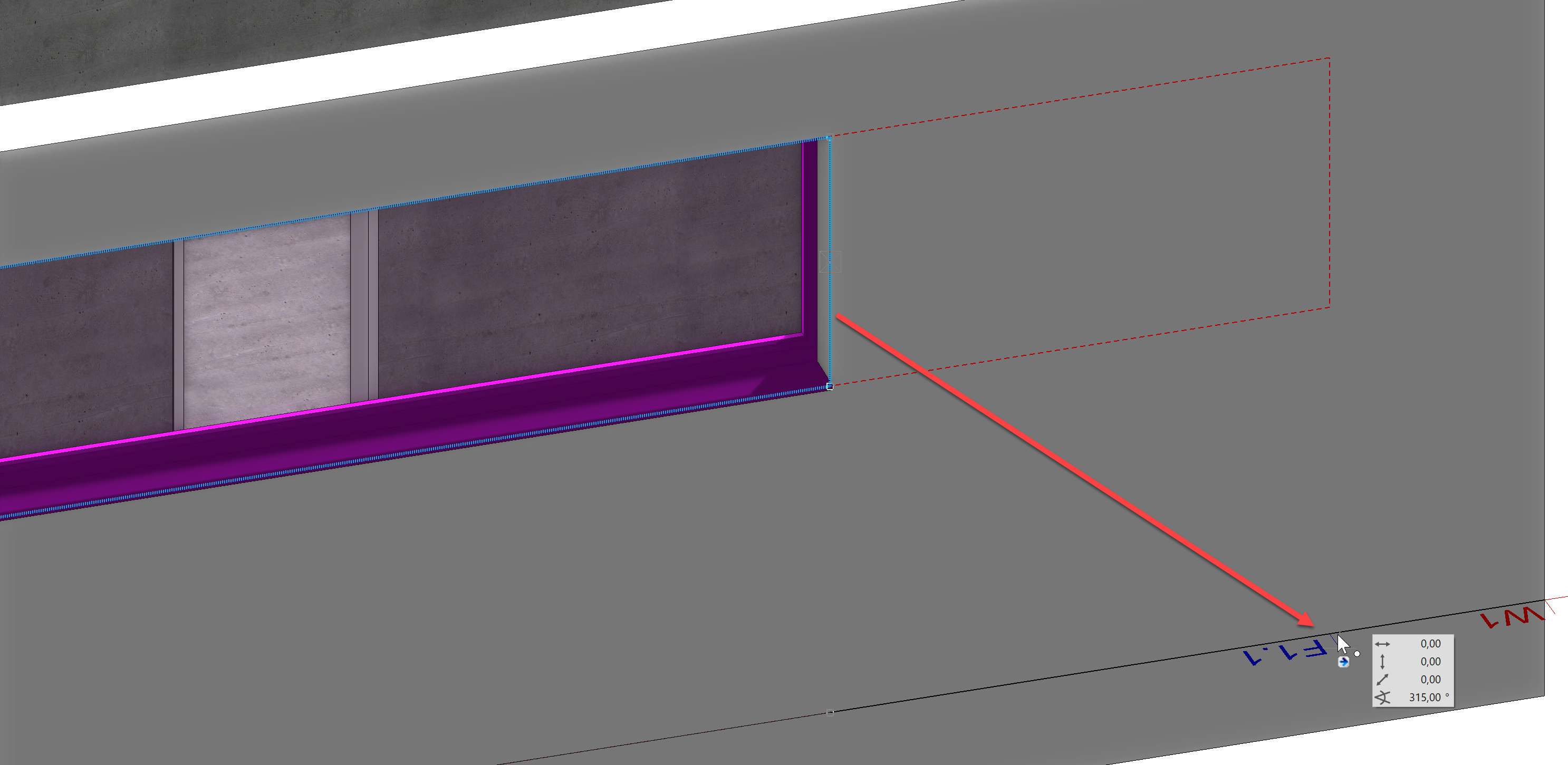
Now the size of the window should be adjusted. Select the window on the right outside edge. Pulling the mouse to the right, will move the window. We do not want to move the window, however, we want to change the size. To do this, select the stretch window option from the input assistant.

Now capture the Point F1.1 to define the window size.
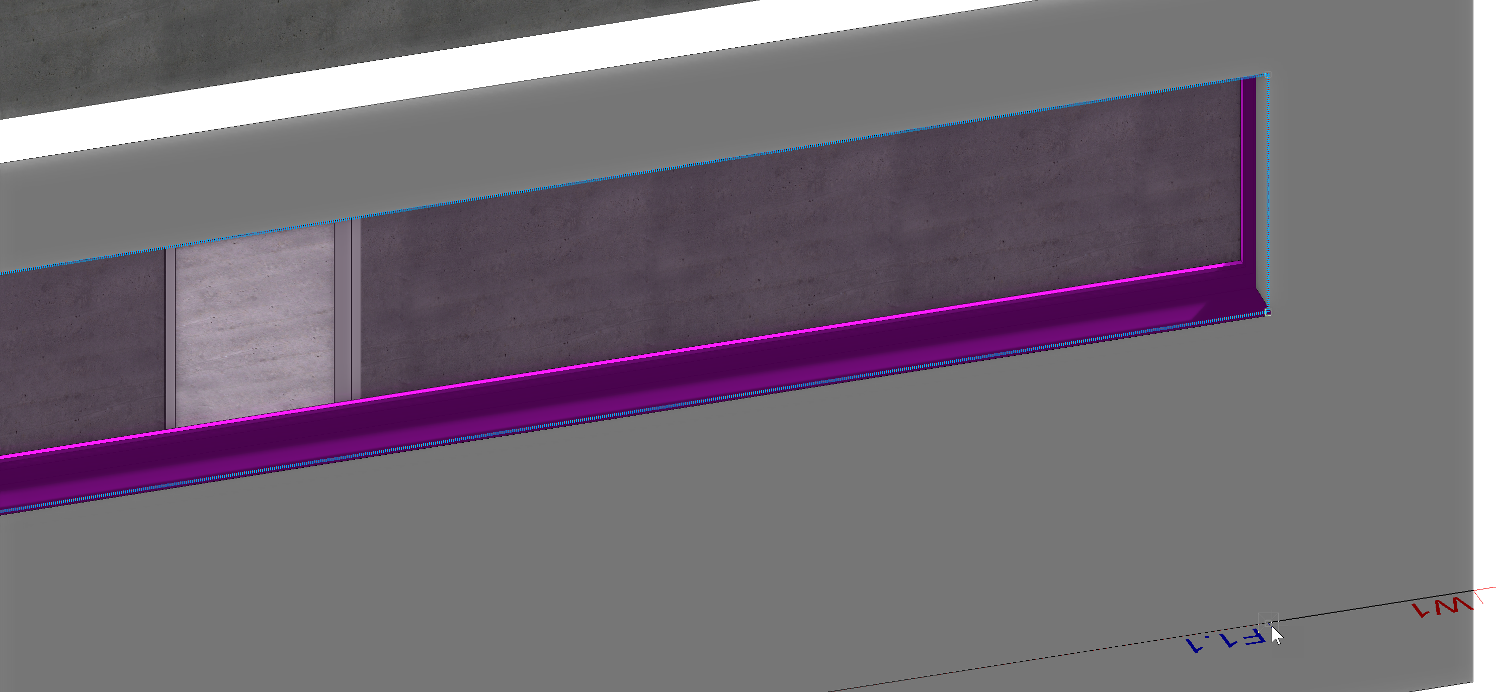
The stretched window should look like this:
Window 1st floor
We continue with the windows on NF1. In order to also show the other variant, we will work in 2D mode. First, show NF1 alone, rotate the model into the floor plan view and activate the wire model depiction.
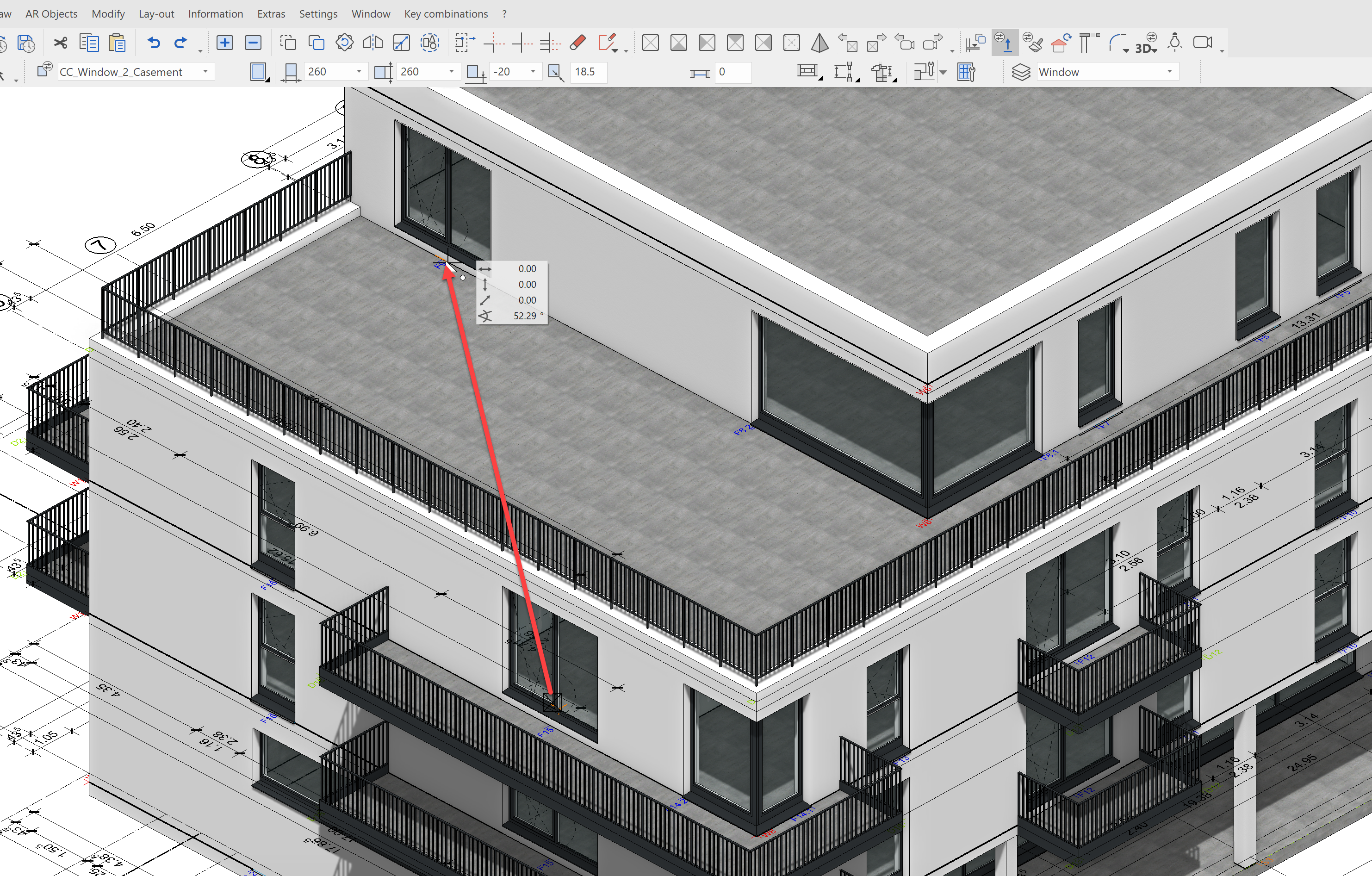
Then, we place the floor-depth window with casement, so that we can later go out onto the balcony. Select the construction part Create window from the tools manager Construction parts and select the data set CC_Window_2_Casements with the dimensions 260 x 260 cm.
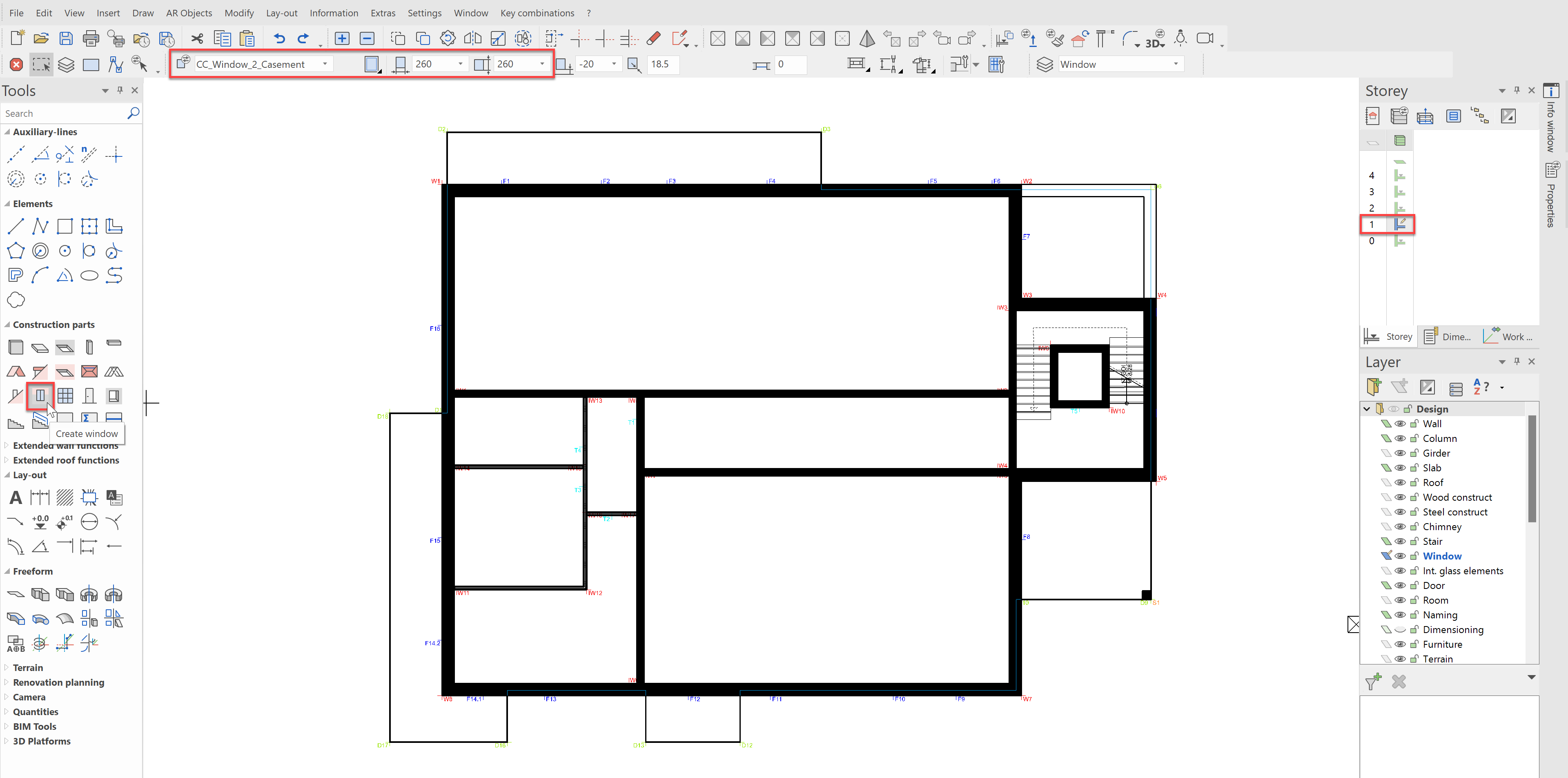
Position the first window on the Point F1, the placement point is in the centre, and the line points outwards as before.
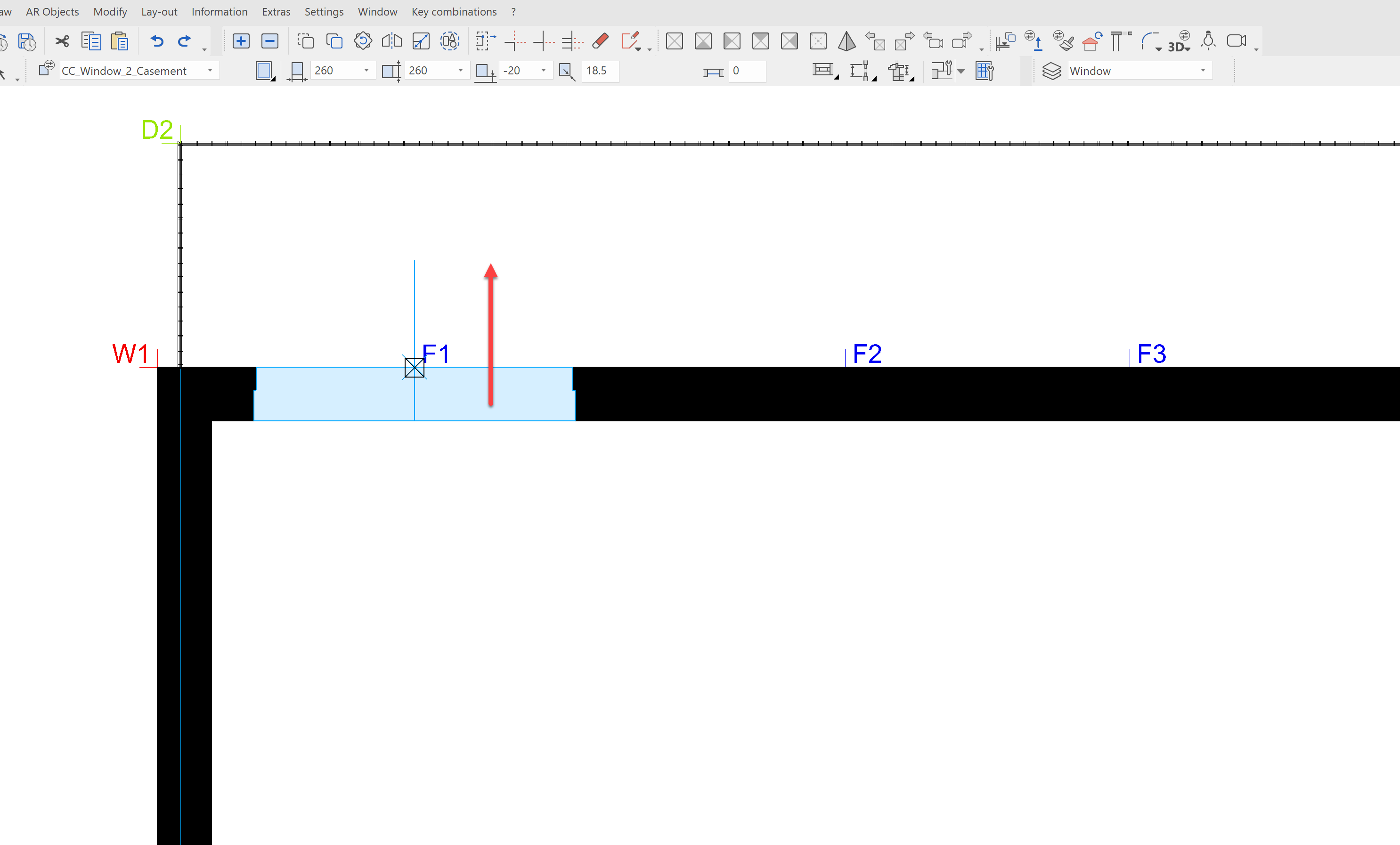
Now place the same window centred on the following points: F1, F4, F7, F8, F12, F15
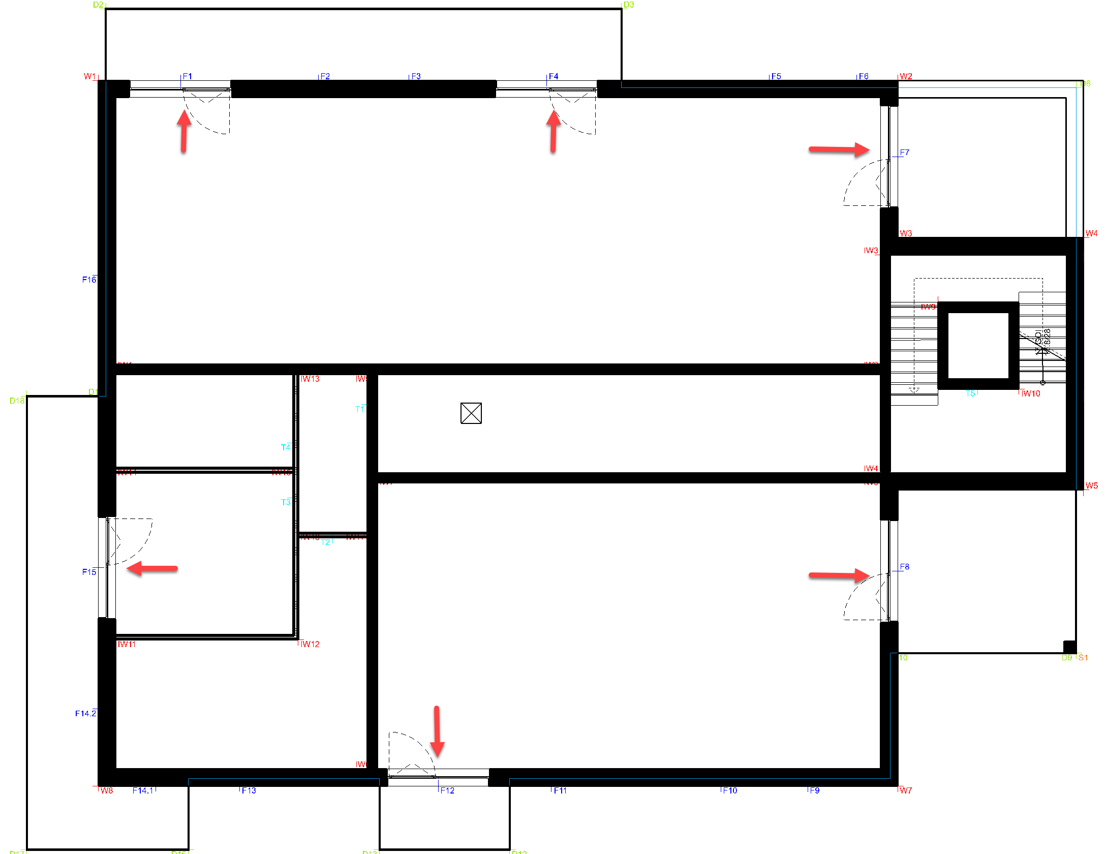
Next, we will place single-casement windows. For these, use the data record CC_Window with the dimensions 120 x 260.
The window should be placed on Points F2 and F3.
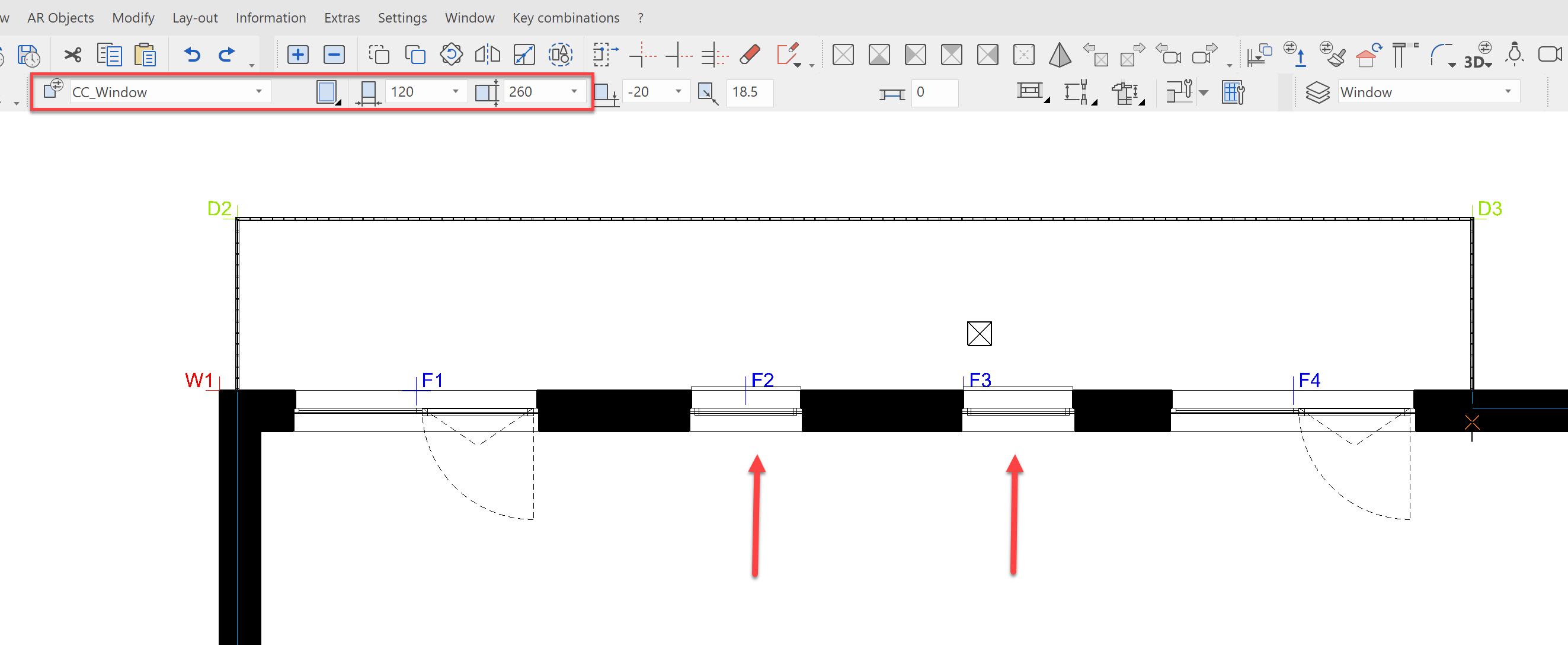
Finally, we will place the windows, which do not open onto balconies. These should have a transom. Select, for this, the data record CC_Window+Transom with the dimensions 120 x 260.
Place this window at the following points: F5, F6, F9, F10, F11, F13, F16
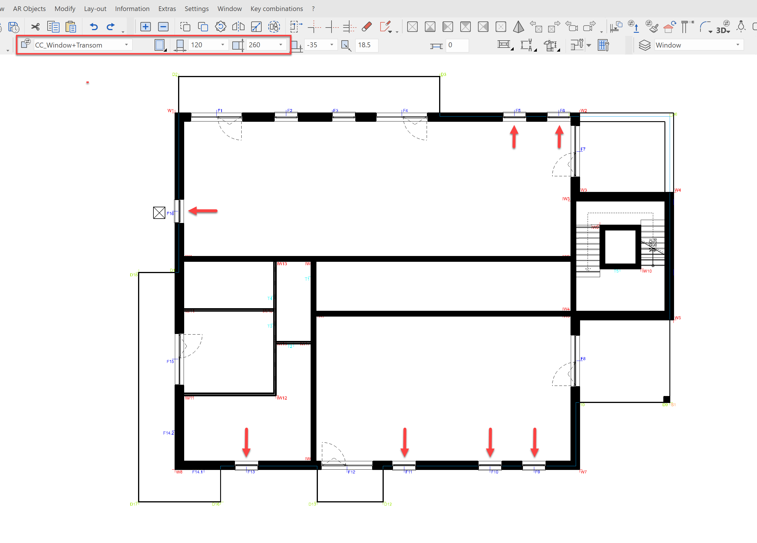
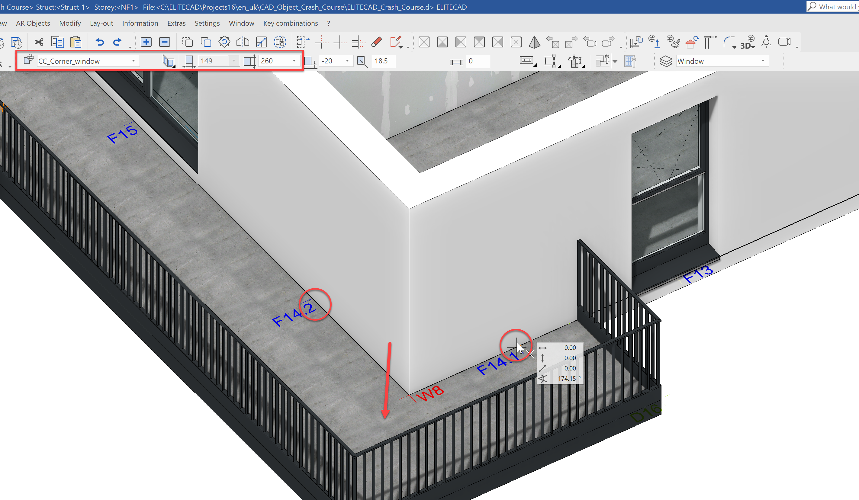
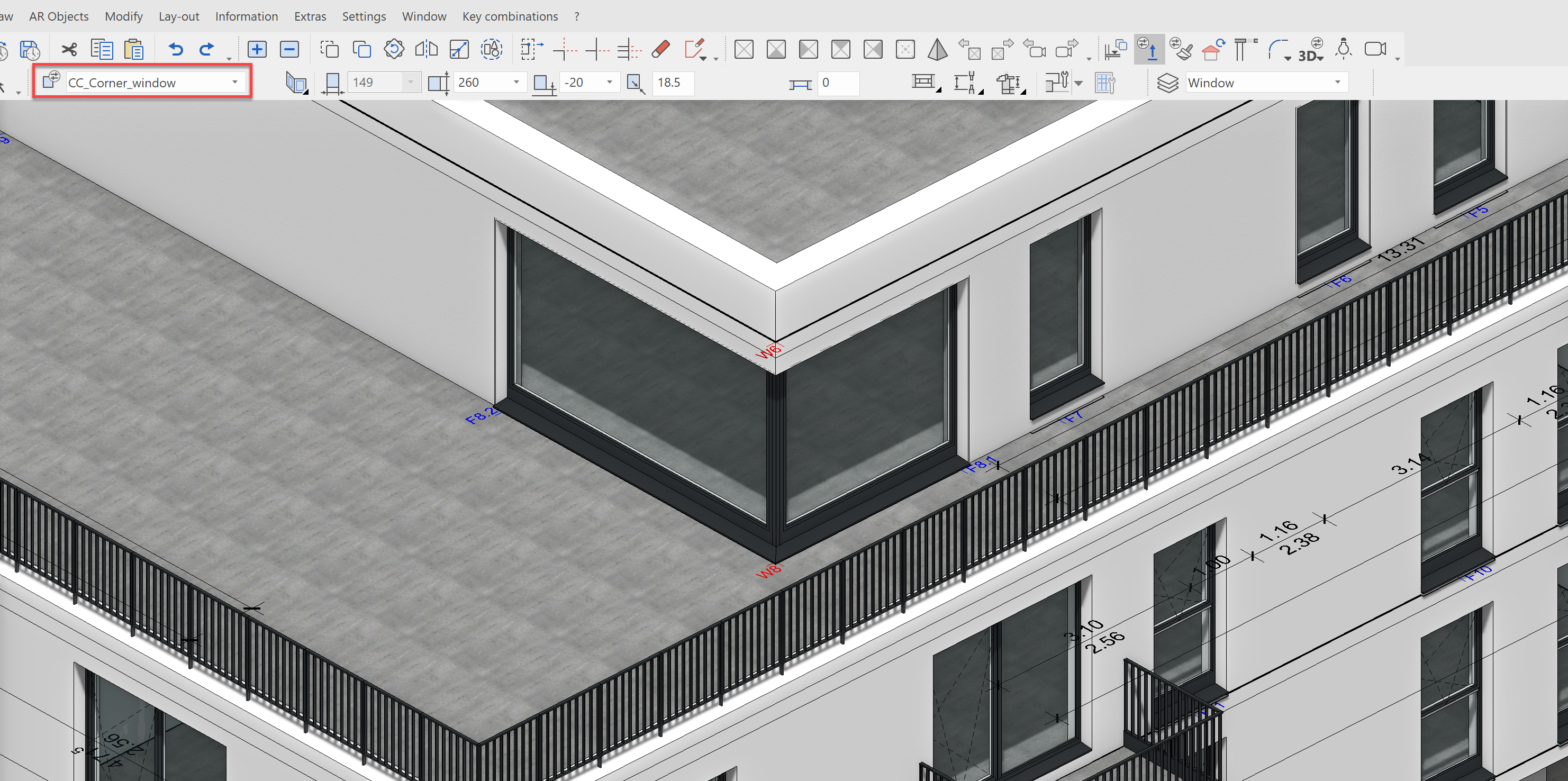
For the last step, we would like a corner window on the balcony side. Select the data record CC_Corner_window with a height of 260 cm. The width is determined by the entry of the points.
Pull the window from Point F14.1 to F14.2. Finally, you must indicate the direction. Again here, click to the outside.
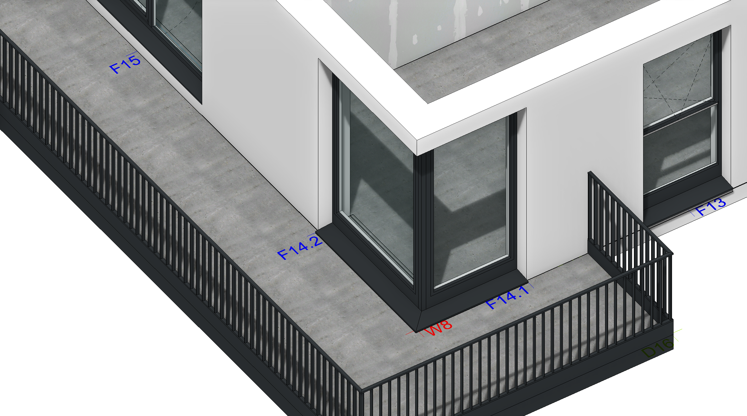
The finished corner window should look like this:
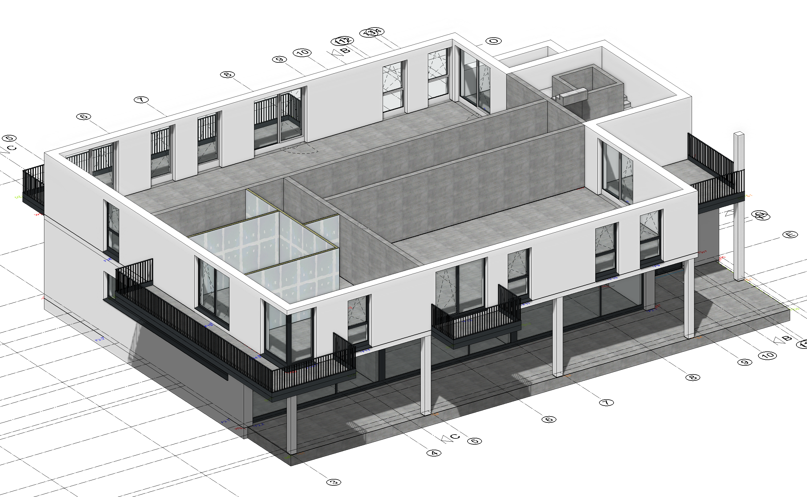
By doing this, the fenestration of our first normal floor is complete. The result should look like this:
Doors 1st floor
Then next thing we will do is to place the doors for NF1. We will begin with the entryway for the apartment.
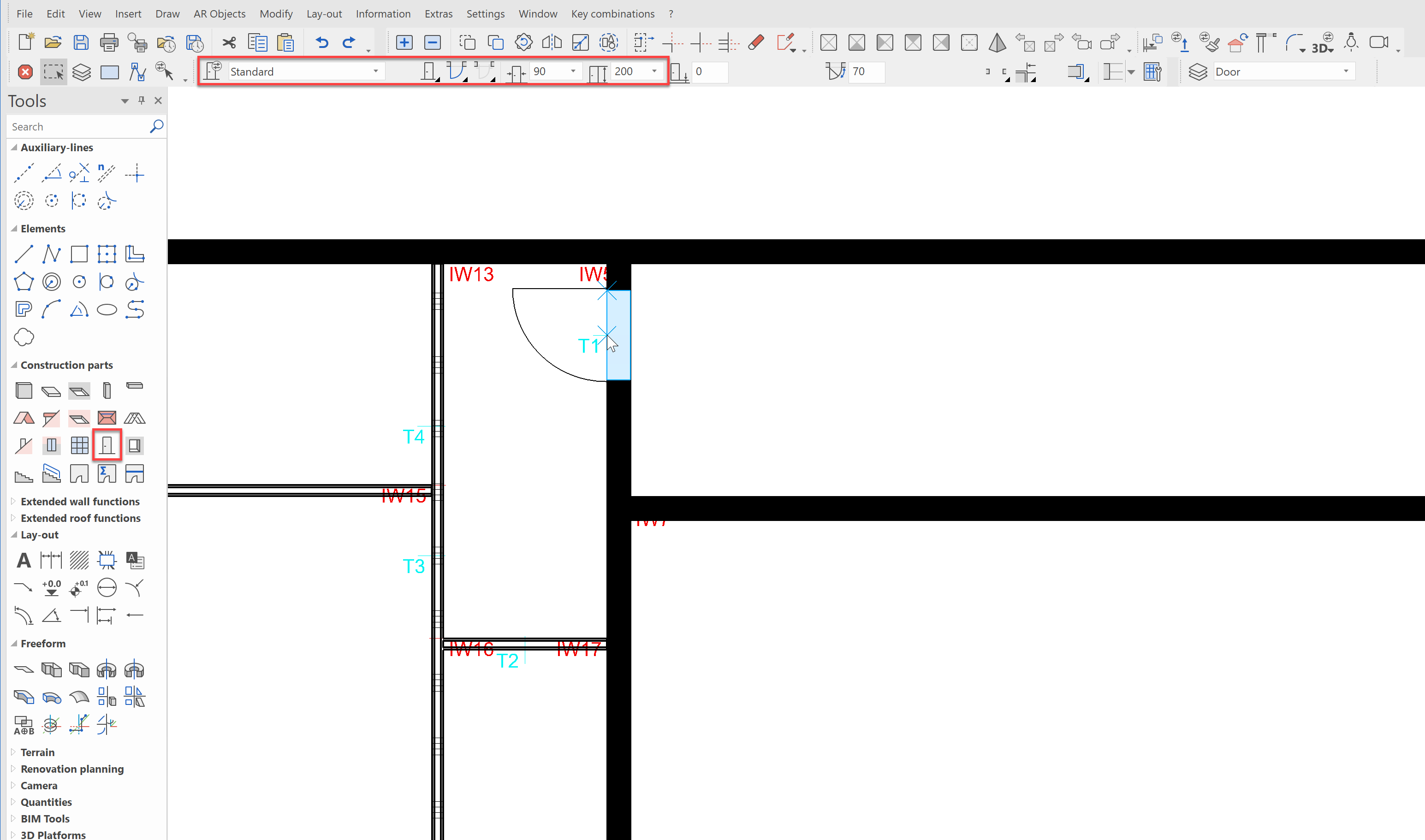
Choose the construction part Create door and the data record Standard with the dimensions 90 x 200 cm. Place the door on Point T1 with it opening into the apartment.
Now adjust the reveal width to 80 cm and place the remaining interior doors at points T2, T3 and T4 with the opening directions indicated below:
This concludes the modelling of the first storey. Of course, we could divide up other apartments, draw in walls, place doors, etc. However, the aim of this course is to show the basic functions of ELITECAD with only a few examples.
Second floor
NF2 should be arranged constructionally identical to NF1. That means, that we want to create all walls, windows, doors, stairs, etc. to be in the same position for this storey. We could now draw all the construction parts again, copy the elements individually to the floor above, or we could do everything in one step.
For that last option, we must first select all of the elements in the NF1, that should be copied into the second storey. In our case, this includes the interior walls, doors, windows, stairs and the elevator shaft.
Show NF1 alone and use the rectangle selection from left to right, as shown in the picture. Attention: Only elements that are completely contained within the selection area will be selected.
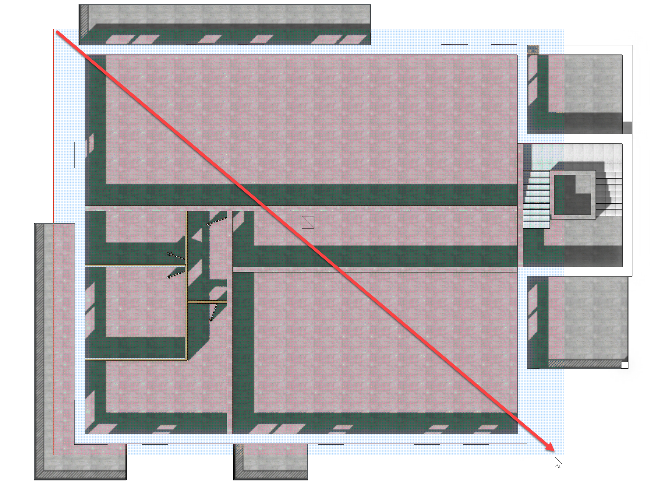
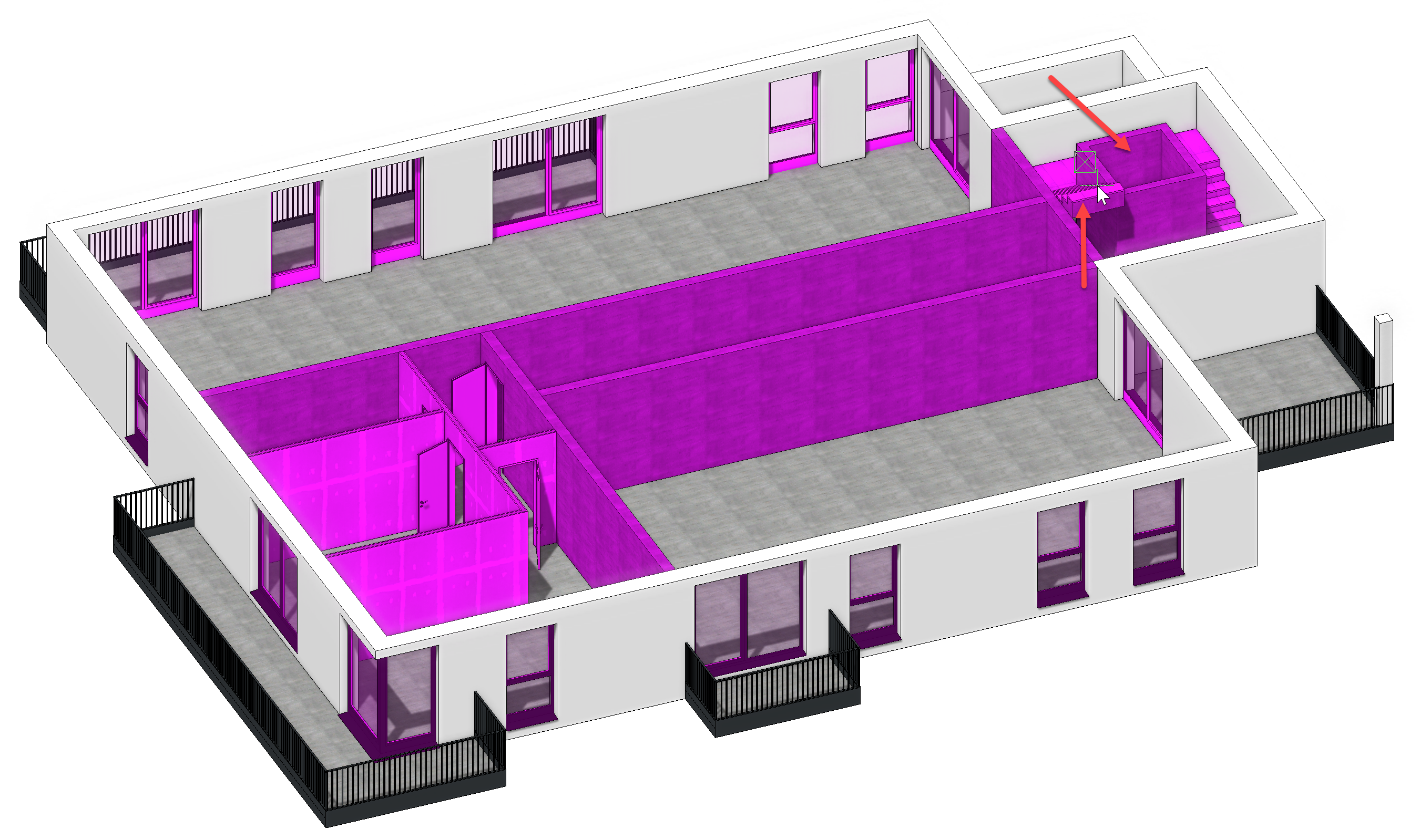
In 3D solid mode, it is easier to see which construction parts have been selected. We see that the stair and the elevator shaft are not included - they were not completely within the selection area. In order to add these, we need to click on the shaft and the staircase while holding the Shift key.
Once this is done, we will activate NF2. Make certain, that the construction parts stay selected. Now, select the already known function Copy into active storey and copy the construction parts into the NF2.
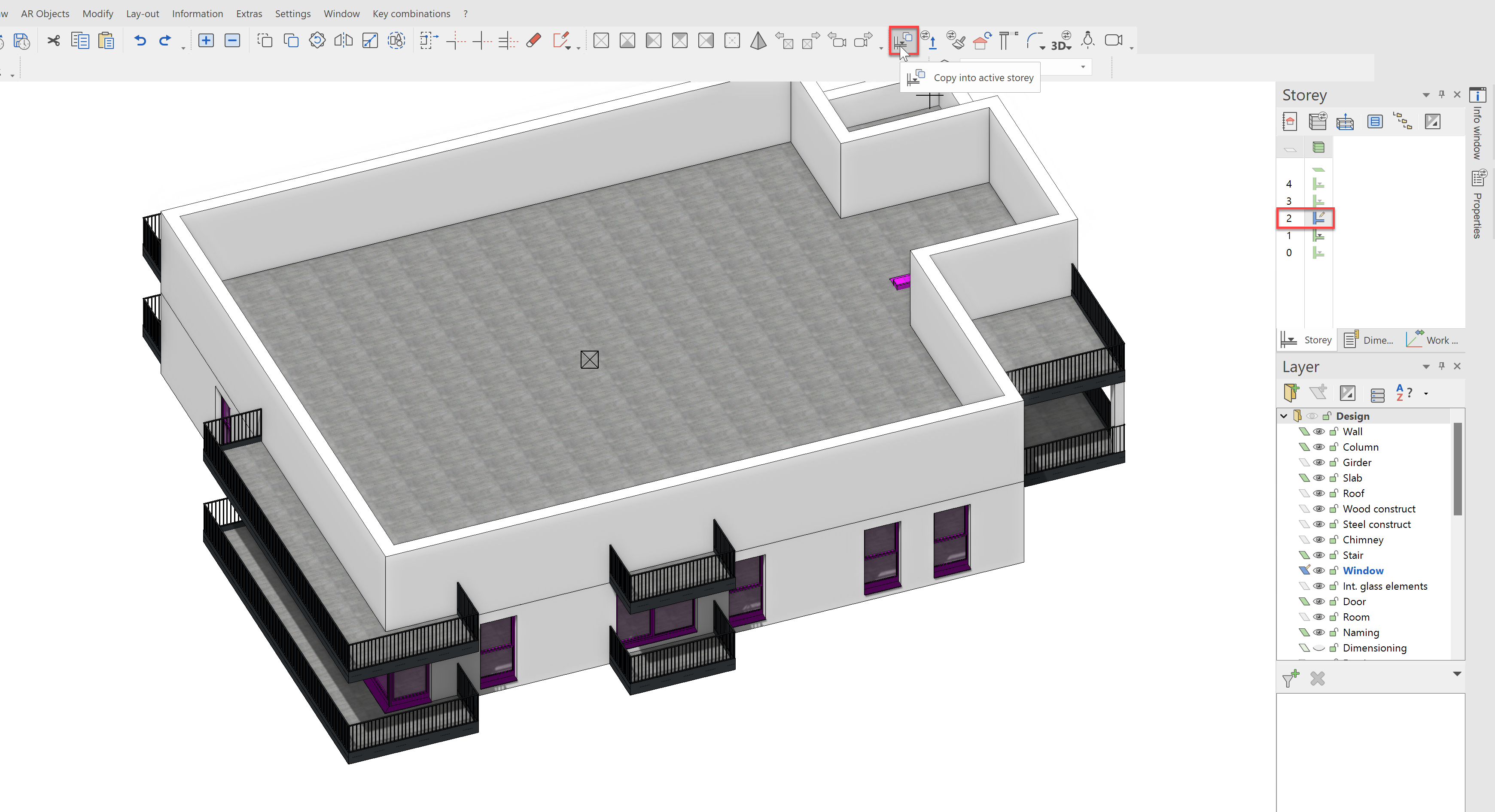
The result should look like this:
Top floor windows
The top storey will need its own fenestration because its floor plan is different. Some windows are similar and can be copied.
Activate the TF1 in the storey manager. Select the 4 windows of the NF2 as shown and copy them into the top storey.
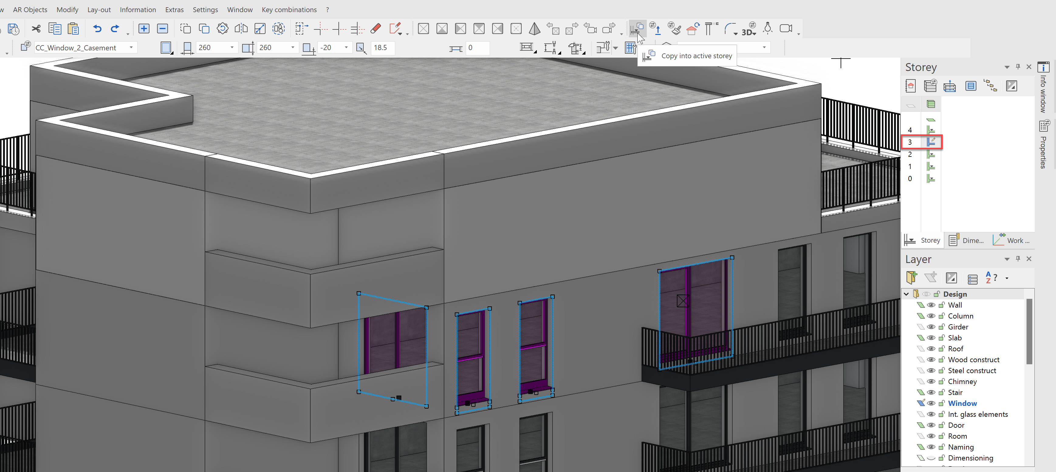
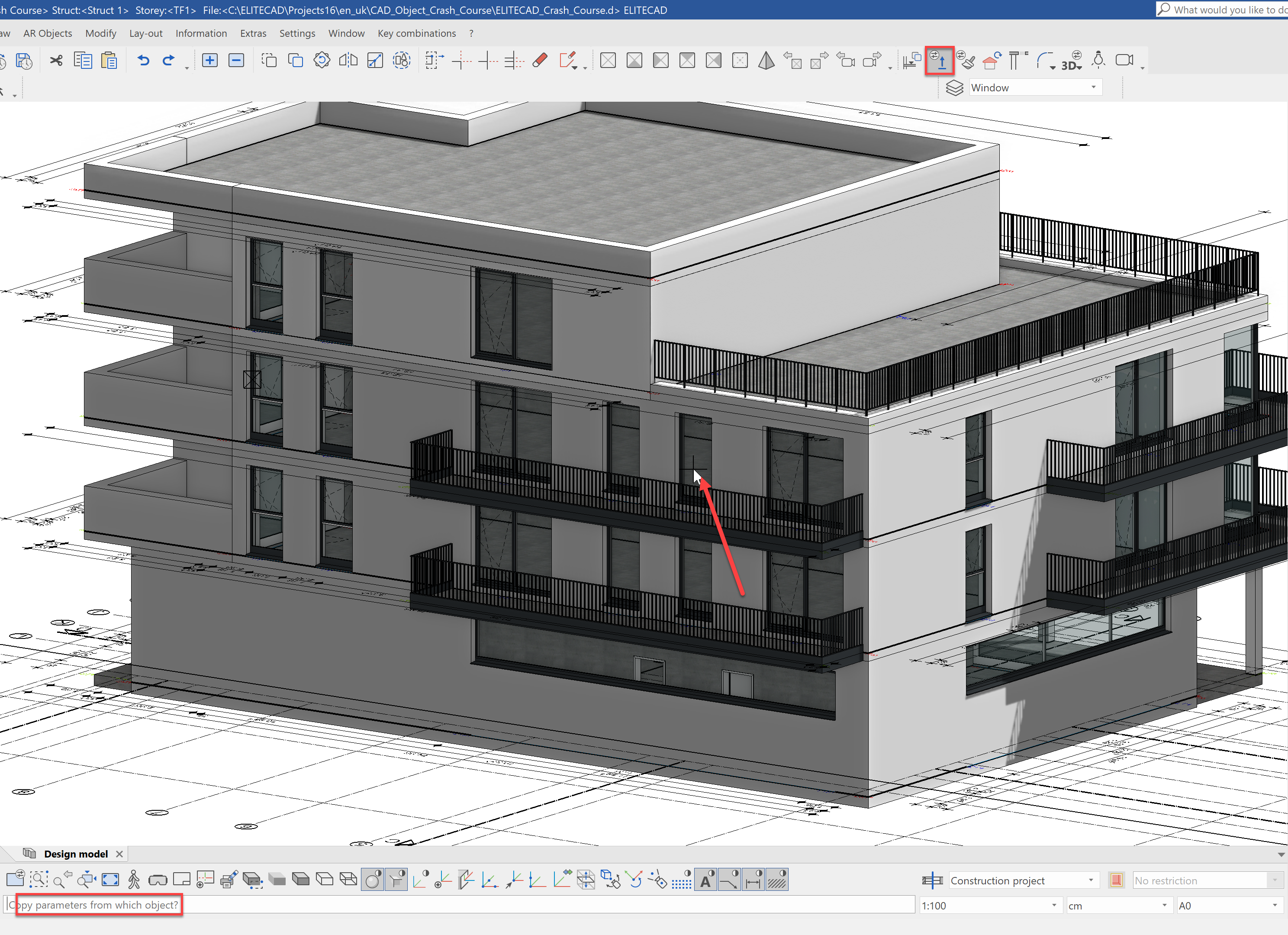
Now place the rest of the windows. We can do this either by selecting the appropriate data record, or by copying the properties of an existing window. We will do this by using the function Copy parameters from the menu bar. Once the function has been started, we need to select the window, from which we want to copy the properties.
Place the window and the points F5, F6 and F7
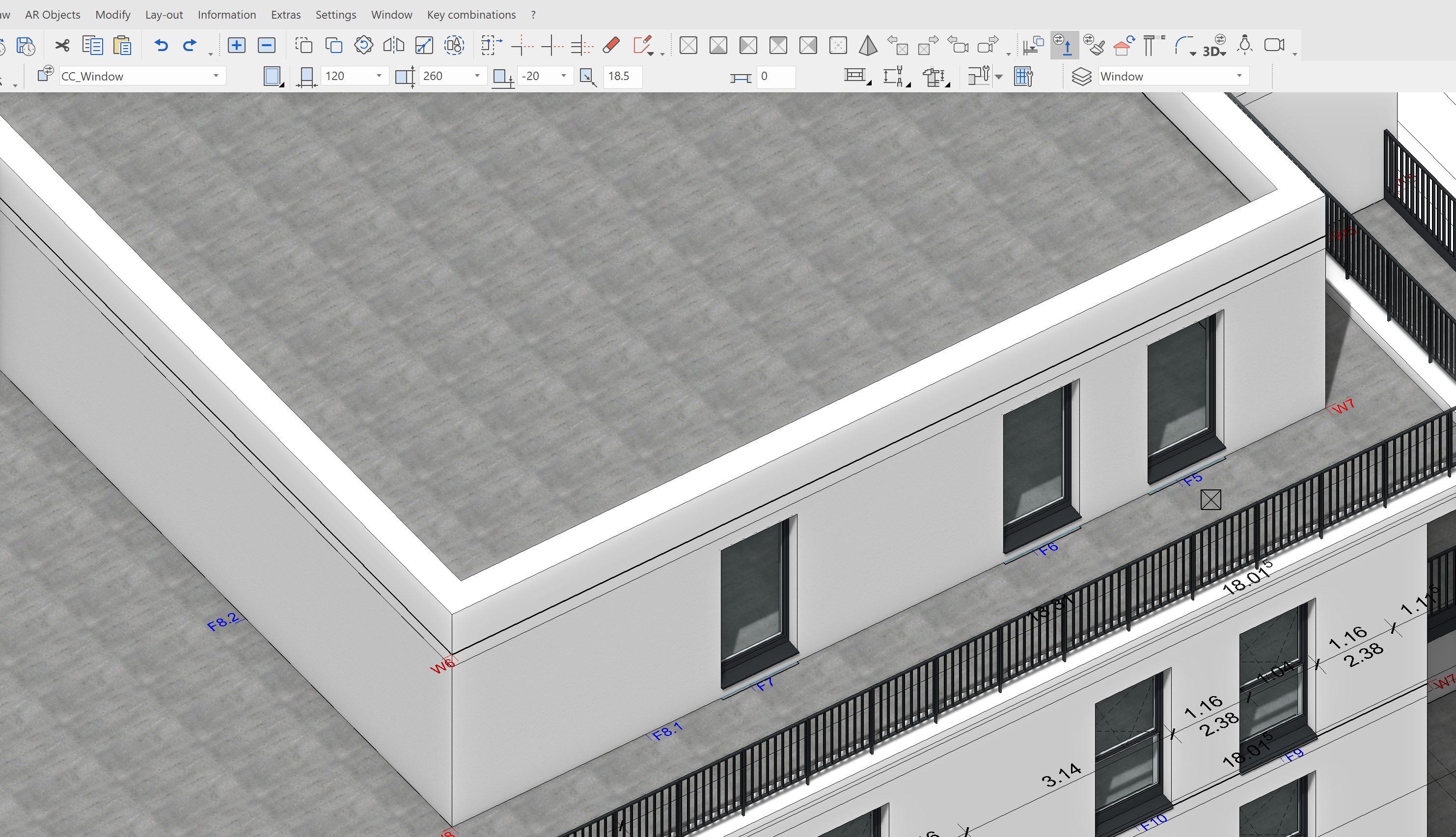
Finally, we will set a corner window with the data record CC_Corner_window from Point F8.1 to Point F8.2
The 2-casement window will be placed using the function Copy parameters at the Point F9.
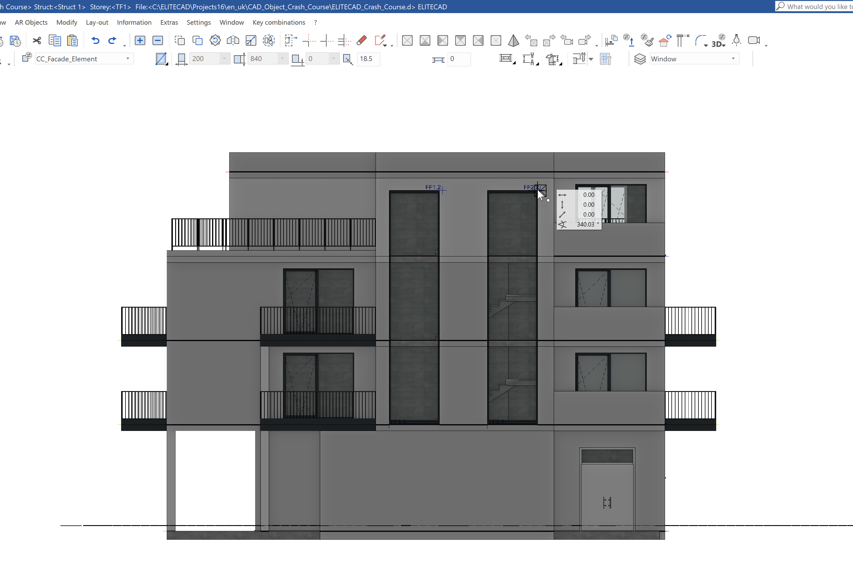
As a small highlight, we wanted to finish by placing a multi-storey window. To do this, we will need to first change the work plane using the function Work plane on surface from the image properties. Using Ctrl+D, we can rotate the view accordingly.
We need to use the data record CC_Fascade_Element and enter the shape with Rectangle over diagonal. Now, draw the first window from Point FF1.1 to Point FF1.2.
For the second window, you can either draw from Point FF2.1 to Point FF2.2 or copy the first window and place it there.
Our building is, at least from the outside, taking shape quite well. In the next chapter, we will concern ourselves with the interior construction.