Interior walls
The next step is to model the interior walls of the building. Here we will show an example of the subdivision of the sales rooms on the ground floor by with concrete walls, as well as the subdivision of an apartment on the first floor using drywall. You are free to further divide the apartment or the floor plans as you wish at the end of this course.
Ground floor
We will start with the GF and show this alone. Switch to the floor plan view using Ctrl+Space and change the view to wire model using Ctrl+D. Be certain that the Aux. Geometry GF is visible.
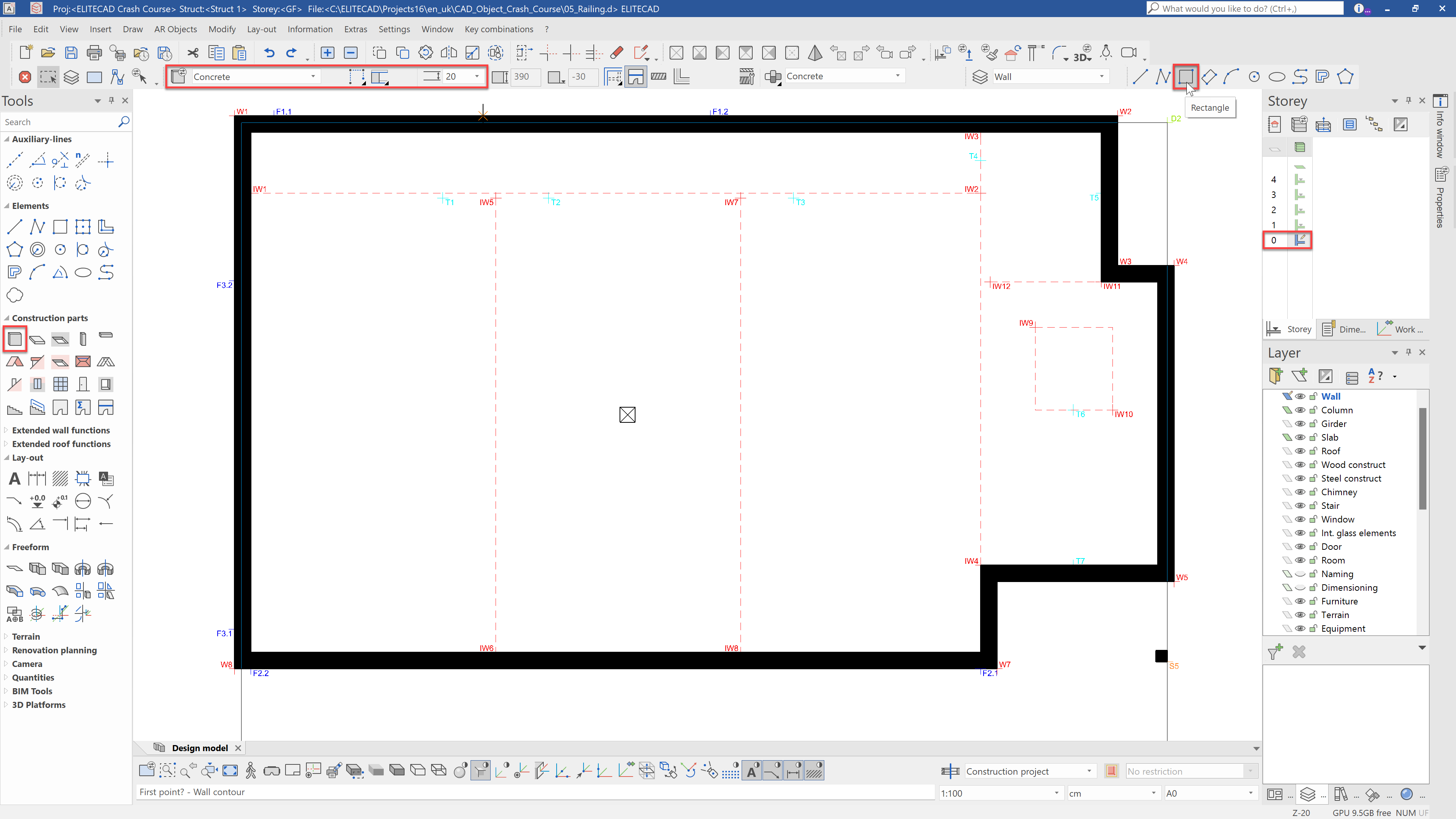
The first wall that we will place is a load-bearing concrete wall around the elevator shaft. Select the construction part Wall and the data record Concrete with a thickness of 20 cm. You can draw the contour either as a polygon or directly as a rectangle.
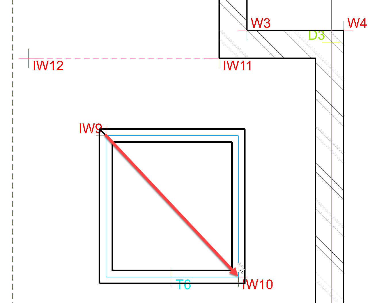
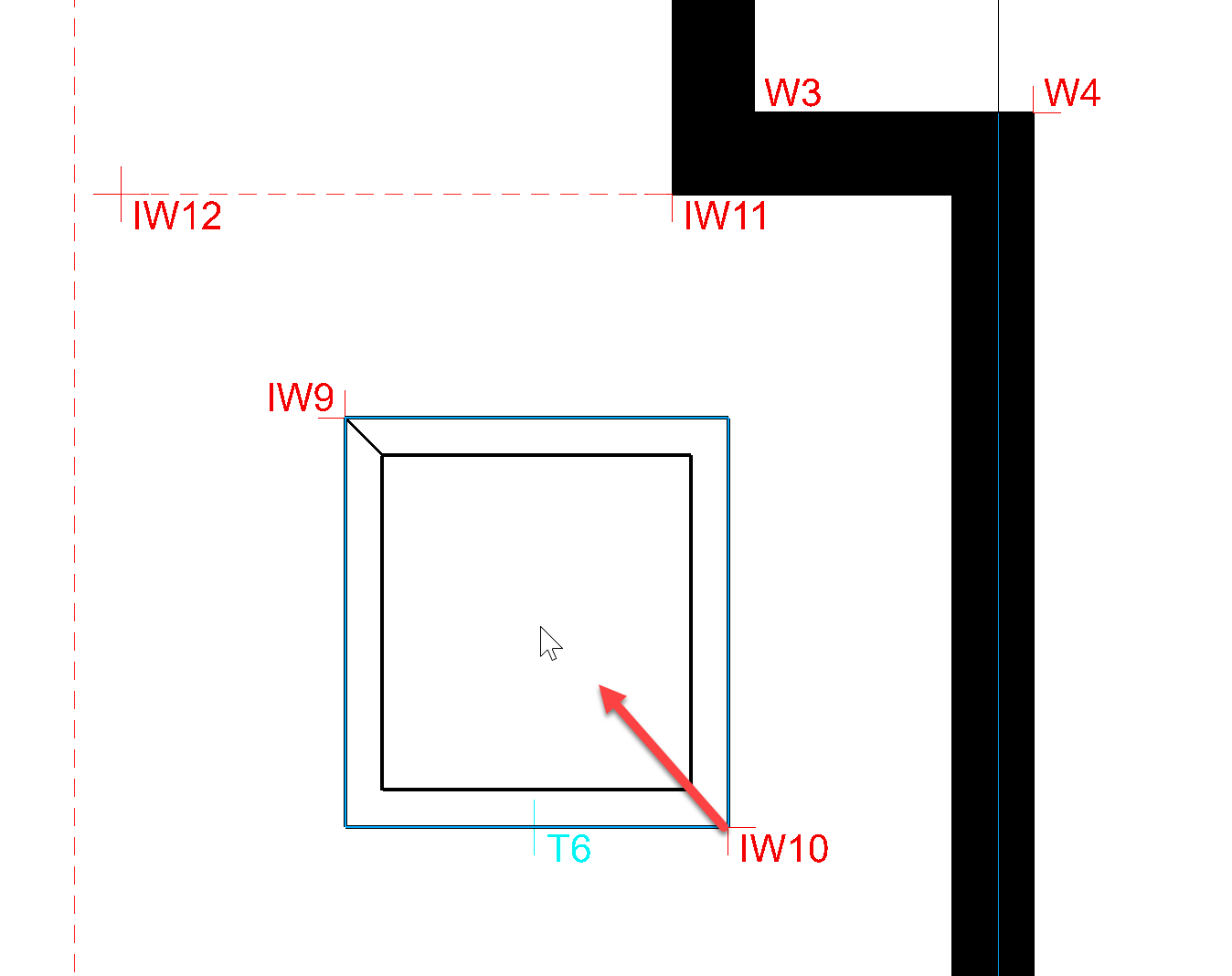
Now create the concrete wall from point IW9 to IW10.
Once you have confirmed the contour with a click, you must specify the wall axis. By moving the mouse, you can see a preview of the planned wall. If you move the mouse inwards, the wall axis will be placed on the outside and vice versa. For our example, the axis should be outside. Move the mouse inwards to do this and create the wall. Now, using the previously introduced function Copy into active storey copy the this wall into NF1 and TF1.
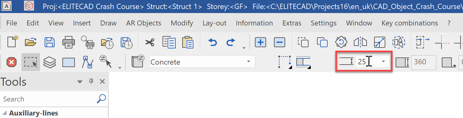
Now we will create the load-bearing interior walls. Once again, select the construction part wall with data record concrete but change the thickness to 25 cm this time.
Create the interior wall from point IW1 to IW2, with wall axis centre.
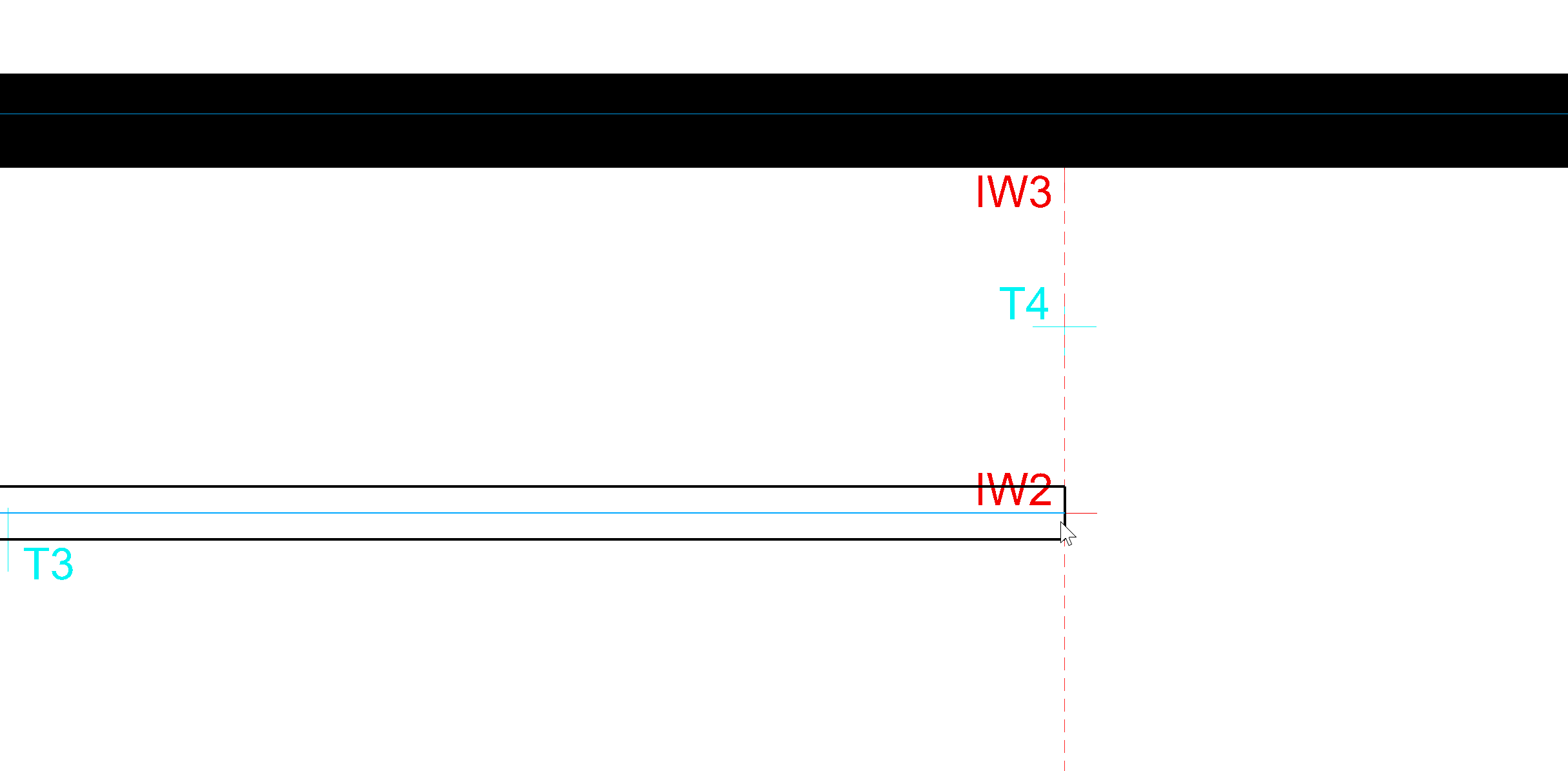
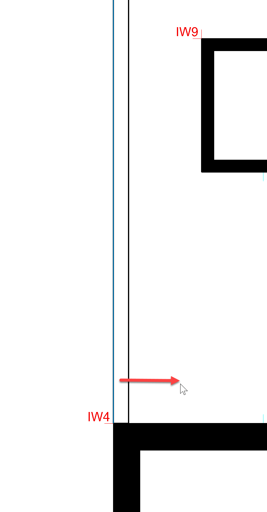
Create an interior wall from IW3 to IW4, with wall axis left (move mouse to the right).
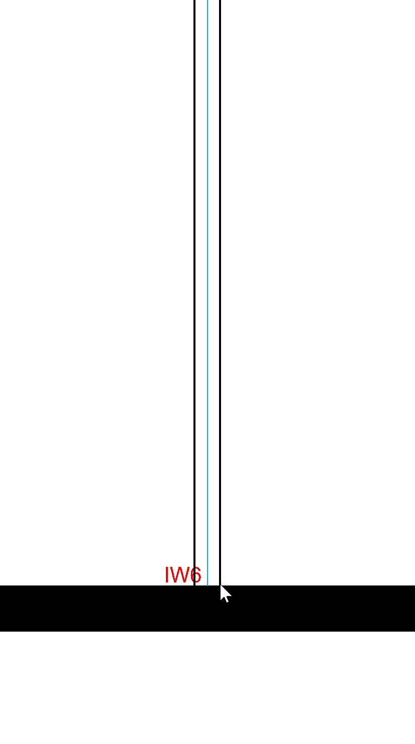
Create an interior wall from IW5 to IW6, and from IW7 to IW8 with wall axis centre (move mouse to the right).
Create an interior wall from IW11 to IW12, with wall axis below

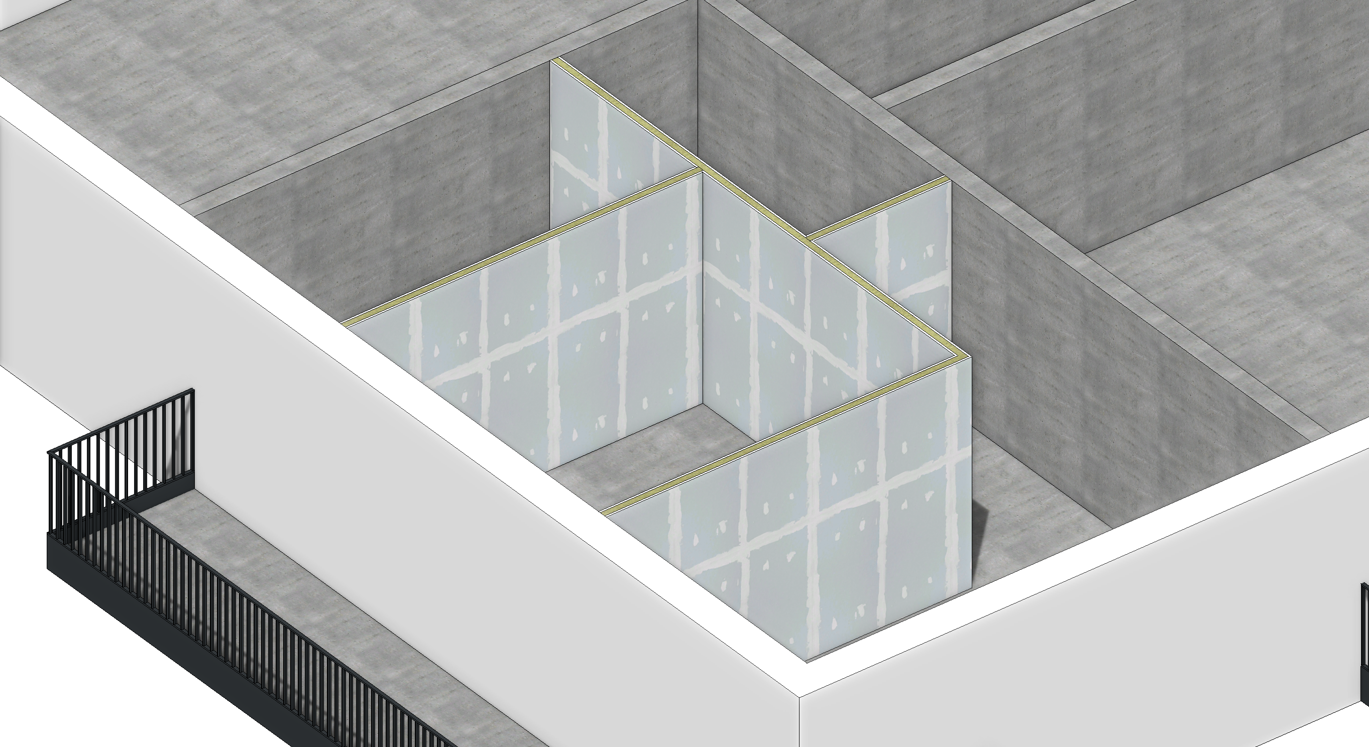
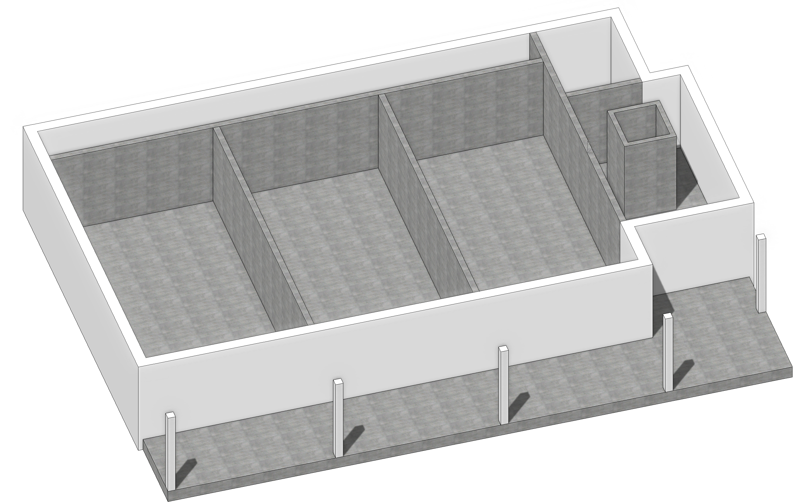
Check the results in the 3D solid depiction. If you have drawn all the interior walls correctly, your result should look like this:
First floor
Now move to the NF1 and install the following concrete walls with a thickness of 25 cm on your own:
Wall 1: IW1 -> IW2, axis centre
Wall 2: IW3 -> IW4, axis left
Wall 2: IW5 -> IW6, axis centre
Wall 4: IW7 -> IW8, axis centre
Wall 5: IW9 -> IW10, axis outside, thickness 20 cm, height reference from lower floor edge to ceiling (if not already copied).
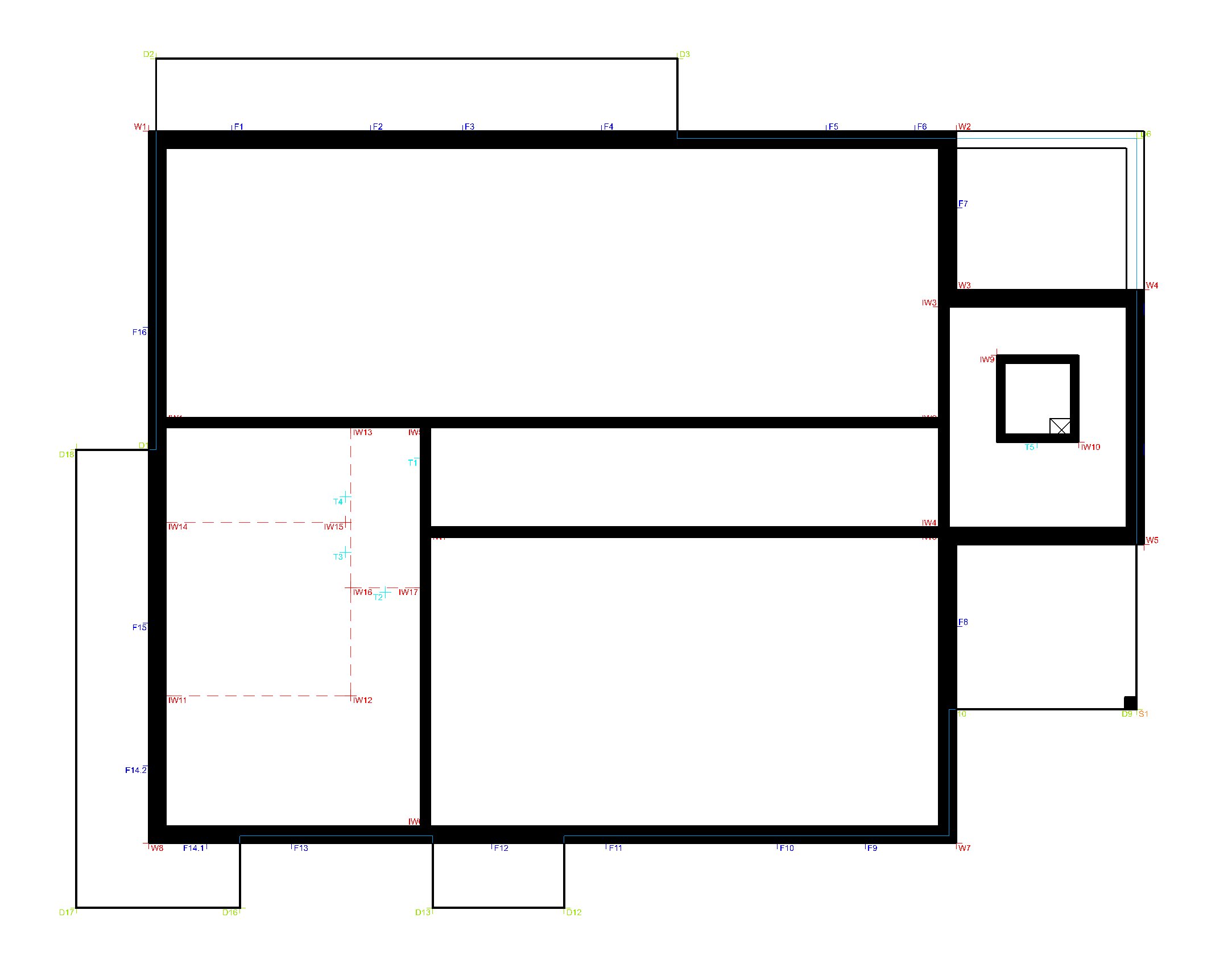
The result should look like this:
After the individual residential units have been divided, we can carry out the expansion of the apartments with a drywall construction.
Select the wall function and the data record CC_Drywall.
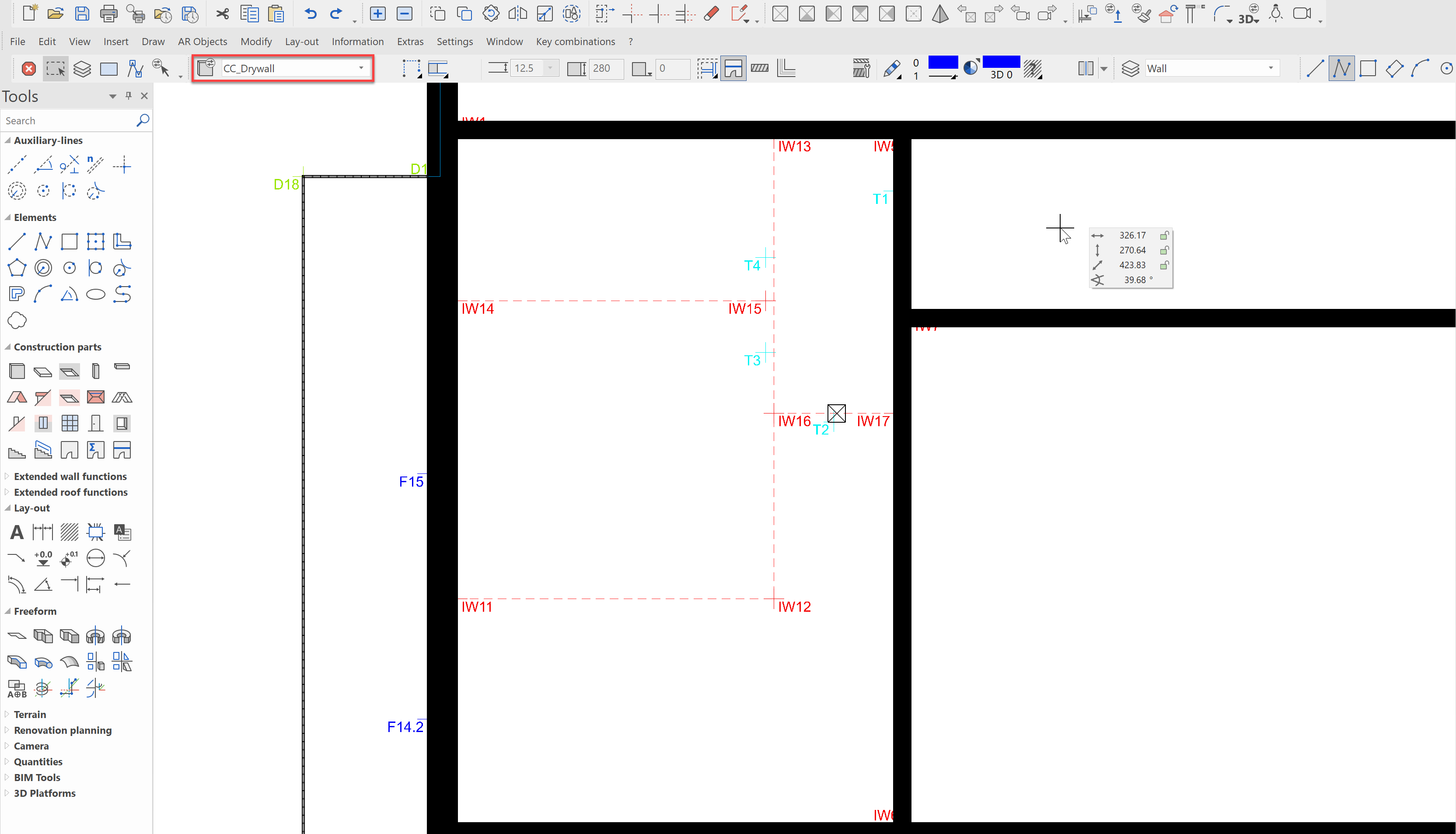
In the lower left apartment, draw the following drywall constructions:
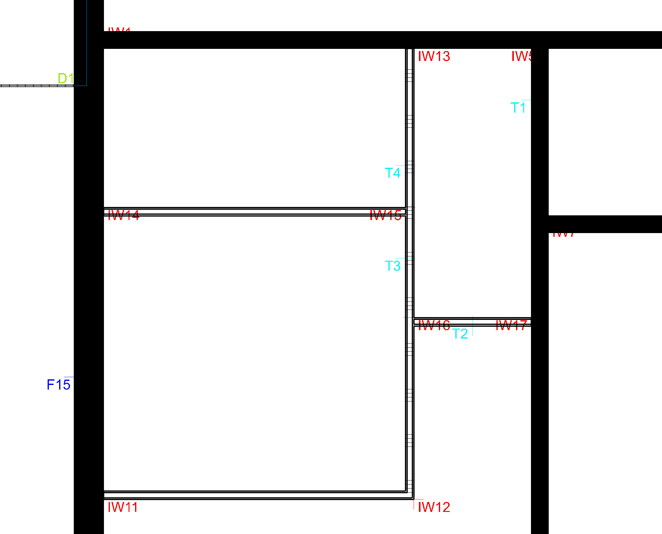
Wall 1: IW11 -> IW12 -> IW13, axis right
Wall 2: IW14 -> IW15, axis above
Wall 3: IW16 -> IW17, axis above
The finished division should look like this:
Check the results in the 3D solid depiction.